manuals.online logo
Brands
  1. Home
  2. •
  3. Brands
  4. •
  5. Axminster
  6. •
  7. Sander
  8. •
  9. Axminster Professional AP2260BS2 User manual

Axminster Professional AP2260BS2 User manual

Code 107708
Original Instructions
AT: 16/07/2021
BOOK VERSION: 06
AP2260BS2
Belt Sander
Achieve professional
results
The sanding belt oscillates for a
scratch-free finish and longer
abrasive life.
Sand at any angle
The sanding belt oscillates for a
Whether you need to sand vertically,
horizontally or any angle in between,
this belt sander is the perfect choice!
Need to carry out curved
work?
The sanding belt oscillates for a
Thanks to the small sanding table,
curved work is a breeze.
Easy to use
The sanding belt oscillates for a With
rack & pinion table adjustment, it is
quick and easy to move the table to
where you need it.
Cert No: BS6X90-1
Axminster Tool Centre Ltd
Axminster Devon
EX13 5PH UK
axminstertools.com
Type Belt Sander
Model AP2260BS2 and conforms to the machinery example for which the
EC Type-Examination Certificate No AE 50397846
has been issued by Laizhou Planet Machinery Co., Ltd.
at:Yutai West Street Laizhou, Shandong 261400 China (Mainland)
and complies with the relevant essential health and safety requirements.
2006/42/EC
2014/30/EU
EN 55014-1:2017
EN 55014-2:2015
declares that the machinery described:-
This machine complies with the following directives:
EU Declaration of Conformity
EN 61000-3-2:2014
EN 61000-3-3:2013
EN 55014-1:2006+A1+A2
EN 55014-2:1997+A1+A2
Signed
Andrew Parkhouse
Operations Director Date: 12/01/2018
1
Warnings
1. Read and understand the entire owner's manual before attempting assembly or operation.
2. Read and understand the warnings posted on the machine and in this manual. Failure to comply with
all of these warnings may cause serious injury.
3. Replace the warning labels if they become obscured or removed.
4. This Oscillating Edge Sander is designed and intended for use by properly trained and experienced
personnel only. If you are not familiar with the proper and safe operation of an edge sander, do not
use until proper training and knowledge have been obtained.
5. Do not use this machine for other than its intended use.
6. Always wear approved safety glasses/face shields while using this Oscillating Edge Sander.
Everyday eyeglasses only have impact resistant lenses; they are not safety glasses.
7. Before operating this edge sander, remove tie, rings, watches and other jewelry, and roll sleeves up
past the elbows. Remove all loose clothing and confine long hair. Non-slip footwear or anti-skid floor
strips are recommended. Do not wear gloves.
8. Wear ear protectors (plugs or muffs) during extended periods of operation.
9. Some dust created by power sanding, sawing, grinding, drilling and other construction activities
contain chemicals known to cause cancer, birth defects or other reproductive harm. Some examples
of these chemicals are:
•Lead from lead based paint.
•Crystalline silica from bricks, cement and other masonry products.
•Arsenic and chromium from chemically treated lumber.
Your risk of exposure varies, depending on how often you do this type of work. To reduce your
exposure to these chemicals, work in a well-ventilated area and work with approved safety
equipment, such as face or dust masks that are specifically designed to filter out microscopic
particles.
10. Do not operate this machine while tired or under the influence of drugs, alcohol or any medication.
11. Make certain the switch is in the OFF position before connecting the machine to the power source.
12. Make certain the machine is properly grounded.
13. Make all machine adjustments or maintenance with the machine unplugged from the power source.
14. Form a habit of checking to see that all extra equipment such as adjusting keys, wrenches, scrap,
stock, and cleaning rags are removed away from the machine before turning on.
15. Keep safety guards in place at all times when the machine is in use. If removed for maintenance
purposes, use extreme caution and replace the guards immediately when maintenance is complete.
16. Make sure the edge sander is firmly secured to the floor before use.
17. Check damaged parts. Before further use of the machine, a guard or other part that is damaged
should be carefully checked to determine that it will operate properly and perform its intended
function. Check for alignment of moving parts, binding of moving parts, breakage of parts, mounting
and any other conditions that may affect its operation. A guard or other part that is damaged should
be properly repaired or replaced.
18. Provide for adequate space surrounding work area and non-glare, overhead lighting.
19. Keep the floor around the machine clean and free of scrap material, oil and grease.
2
20. Keep visitors a safe distance from the work area. Keep children away.
21. Make your workshop child proof with padlocks, master switches or by removing starter keys.
22. Give your work undivided attention. Looking around, carrying on a conversation and “horse-play” are
careless acts that can result in serious injury.
23. Maintain a balanced stance at all times so that you do not fall or lean against the sanding belt or other
moving parts. Do not overreach or use excessive force to perform any machine operation.
24. Use the right tool at the correct speed and feed rate. Do not force a tool or attachment to do a job for
which it was not designed. The right tool will do the job better and safer.
25. Use recommended accessories; improper accessories may be hazardous.
26. Maintain machinery with care. Follow instructions for lubricating and changing accessories.
27. Turn off the machine before cleaning. Use a brush or compressed air to remove dust or debris — do
not use your hands.
28. Do not stand on the machine. Serious injury could occur if the machine tips over.
29. Never leave the machine running unattended. Turn the power off and do not leave the machine until it
comes to a complete stop.
30. At all times hold the stock firmly.
Familiarize yourself with the following safety notices used in this manual:
This means that if precautions are not heeded, it may result in minor injury and/or
possible machine damage.
This means that if precautions are not heeded, it may result in serious injury or possibly
even death.
Specifications
01) Work table size (mm):
750x250
02) Table travel (mm): 80(up and down)
03) Belt size (mm): 2260x150
04) Belt table size (mm) : 820x170
05) Belt table tilt (mm): 0 -90°
06) Dust chute diameter (mm):100
07) Motor (W): 2200W
08) Packing size (mm):1350x650x605 (one case)
The above specifications were current at the time this manual was published, but because of
our policy of continuous improvement, the manufacturer reserves the right to change specifications
at any time and without prior notice,without incurring obligations.
3
Assembl
y
Stand Assembly
Referring to Figure 1:
1. Remove all contents from the shipping
container.
2. Clean all rust protected surfaces with a mild
solvent. Do not use paint or lacquer thinner,
gasoline, or mineral spirits; these will damage
painted surfaces.
3. Attach the four rubber pads (A) to the bottoms
of the side panels (C) with four each
hex nuts (B). The hardware can be found
in the bag with the rubber pads.
4. Attach the side panels (C) to the front panel (D)
with four 5/16” x 5/8” hex cap screws, eight
5/16” flat washers, four 5/16” lock washers, and
four 5/16” hex nuts (E). Hand tighten the
hardware at this point.
Note: Assemble the stand upside down to
make sure that the tops of the panels are flush.
5. Mount the shelf (F) to the inside of the stand
with two M5x10 pan head screws, two M5 flat
washers and two M5 lock washers (G).
6. Finish the stand assembly by attaching the rear
panel (H) to side panels (C) with four
5/16” x 5/8” hex cap screws, eight 5/16” flat
washers, four 5/16” lock washers, and four
5/16” hex nuts (J).
7. Make sure stand is sitting evenly on a level
surface before tightening hardware.
Installing Table and Motor Unit to Stand
The Table and Motor Unit is
heavy! Use great care and adequate resources
when lifting the unit up onto the stand! Failure
to comply may cause serious injury and/or
damage to the sander and/or property!
Referring to Figure 2:
1. With the aid of another person, carefully lift the
table and motor unit (A) out of the shipping
box, and up onto the stand (B).
2. Line up threaded holes in the base (C) with the
holes in the stand (D).
3. Open the cabinet door (E) and through the
opening attach main unit to stand with two
5/16” x 1-1/4” hex cap screws (F), two 5/16”
lock washers (G) and two 5/16” flat
washers (H). Tighten with a 12mm wrench.
Figure 2
4
Referring to Figure 3:
4. The sanding platen (A) is presently in the
horizontal position. Pull lock handle (B) forward
to unlock the platen assembly.
5. Tilt sanding platen to the vertical position (C),
which will look like D in Fig. 4; then push the
lock handle (B) to lock the platen assembly in
place.
Note: Do not turn the lock handle. Turning or
rotating the lock handle will change the tension
of the locking assembly. This may cause the
locking assembly not to work, making it
necessary for adjustment before using the
machine.
Sanding Belt Installation
Referring to Figure 5:
1. From the rear of the sander, remove the belt
guard (A) by unscrewing two lock knobs (B).
Take out the sanding belt and removable fence
from behind the belt guard.
2. Place the handle (C) on belt tensioning
lever (D). Remove the tension from the
mechanism by moving the handle (C) to the
Loose position.
3. Place belt on both rollers so that the edge of
the belt is even with the edge of the rollers.
Note: Make sure that direction arrow on belt
matches the direction indicator on the top of
the platten.
4. Tighten the belt by moving the tension arm
handle (C) to the Tight position. Rotate the belt
by hand in the direction indicated by the arrow
on top of the platten. If the belt tracking needs
adjustment, see Belt Tracking Adjustment
Figure 3
Figure 4
Figure 5
.
5
Extension Table
Referring to Figure 7:
1. Attach the bracket (E) for the extension table to
the side of the motor housing (D) and secure
with two socket head cap screws (F).
2. Slide the shaft of the extension table (C) into
the bracket (E), positioning the table so the
opening (B) wraps around the drive drum (A).
3. Insert lock knob (G) into the threaded hole on
the side of the bracket (E) visible from the rear
of the sander.
Figure 7
Electrical
Grounding Instructions
This sander must be
grounded while in use to
protect the operator from electric shock.
In the event of a malfunction or breakdown,
grounding provides a path of least resistance for
electric current to reduce the risk of electric
shock. This tool is equipped with an electric
cord having an equipment-grounding conductor
and a grounding plug. The plug must be
plugged into a matching outlet that is properly
installed and grounded in accordance with all
local codes and ordinances.
Do not modify the plug provided. If it will not fit
the outlet, have the proper outlet installed by a
qualified electrician. Improper connection of the
equipment-grounding conductor can result in a
risk of electric shock. The conductor, with
insulation having an outer surface that is green
with or without yellow stripes, is the equipment-
grounding conductor. If repair or replacement of
the electric cord or plug is necessary, do not
connect the equipment-grounding conductor to a
live terminal.
Check with a qualified electrician or service
personnel if the grounding instructions are not
completely understood, or if in doubt as to
whether the tool is properly grounded. Use only
three wire extension cords that have three-prong
grounding plugs and three-pole receptacles that
accept the tool’s plug.
Repair or replace a damaged or worn cord
immediately.
6
Extension Cords
Make sure your extension cord is in good
condition. When using an extension cord, be sure
to use one heavy enough to carry the current your
machine will draw. An undersized cord will cause
a drop in the line voltage resulting in power loss
and overheating. Table 1 shows the correct size to
use depending on the cord length and nameplate
ampere rating. If in doubt, use the next heavier
gauge. Remember, the smaller the gauge number,
the heavier the cord.
Adjustments
Sanding Platen Angle Adjustment
Referring to Figure 10:
1. Disconnect the machine from the power
source.
2. Pull the lock handle (B) forward (unlock) to
release tension.
Move the sanding platen (A) to the desired
position. Use a combination square between
the table and sanding platen to get precise
angles.
3. Hold the platen (A) while locking the handle.
Platen Lock Tension Adjustment
1. Disconnect the machine from the power
source.
2. Loosen (unlock) the handle (B, Fig. 10) and
place the platen in the horizontal position as
shown in (A, Fig. 10). Do not lock.
3. Tension eccentric block by tightening the
nut (B, Fig. 11) with a 14mm wrench. Turn the
nut in by 1/4 turn increments and test locking
handle for proper tension.
The lock handle is properly tensioned when it
requires positive force to move the eccentric
block (attached to the locking handle) from one
side to the other. The platen and motor
assembly must stay in a locked position
without sliding once the handle has been
moved to the locked position. Re-adjust as
necessary.
Recommended Extension Cord Gauges
Amps Extension Cord Length in Feet *
25 50 75 100 150 200
< 5 16 16 16 14 12 12
5 to 8 16 16 14 12 10 NR
8 to 12 14 14 12 10 NR NR
12 to 15 12 12 10 10 NR NR
15 to 20 10 10 10 NR NR NR
21 to 30 10 NR NR NR NR NR
*based on limiting the line voltage drop to 5V at 150% of the
rated amperes.
NR: Not Recommended. Table 1
Figure 10
Figure 11
7
Changing the Sanding Belt
Referring to Figure 12:
1. Disconnect the machine from the power
source.
2. Lock the sanding platen in the vertical position
(see the Sanding Platen Angle Adjustment
section on page 12).
3. Release tension on the belt by loosening the
handle (C).
4. Loosen or remove the lock knobs (B) and
remove the belt guard (A).
5. Remove the old belt and install the new belt
matching the direction of the arrows on the belt
with the arrow label on the top of the platen.
6. Line up edge of belt with edge of rollers.
7. Place tension on the belt by moving the
tension arm handle (C) to the Tight position.
8. Reinstall the belt guard (A) and tighten the lock
handles (B)
Note: Belts stretch with wear. When a belt is
replaced, you may have to adjust tracking.
Belt Tracking Adjustment
The Belt Tracking Adjustment is a fine adjustment
procedure. The Motor Mount Tracking Adjustment
(following section) is a course adjustment.
To adjust the belt tracking:
1. Disconnect the machine from the power
source.
2. Push the belt by hand from left to right (the
direction indicated top of the platen) and
observe the belt’s position on the rollers. The
oscillating movement of the belt is by design.
Observe the belt's range of movement from its
highest to lowest position. The edges of the
belt should not have a tendency to move
above or below the edges of the rollers.
If adjustment is still necessary:
3. Insert the round shaft of the belt tracking tool
(provided) into the micro adjust lock nut (A)
and turn away from you to loosen.
4. Turn the micro adjusting screw (B) in 1/4 turn
increments until the belt tracks evenly on the
rollers when rotated by hand.
Tip: Moving the belt tracking tool away from
you raises the belt on the drum and towards
you lowers the belt on the drum.
5. Tighten the micro adjusting nut (A).
Figure 12
Figure 13
6. Connect the machine to power.
7. Turn on the power to the machine and observe
the belt’s up and down range of movement.
Adjustment is correct when the edges of the
belt do not move above or below the edges of
the rollers.
8. When adjustment is complete, tighten the micro
adjust lock nut (A).
If the tracking cannot be corrected go to the Motor
Mount Tracking Adjustment section (next page).
8
Motor Mount Tracking Adjustment
Referring to Figure 14:
bolts (A) on the motor plate. These are set at the
factory and should not require any further
adjustment. If, however, you are not able to track
the belt with the Belt Tracking Adjustment
described in the previous section, the motor mount
bolts will have to be adjusted.
Note: The Motor Mount Tracking Adjustment is a
course adjustment. Use the Belt Tracking
Adjustment first for fine adjustment. If it cannot be
adjusted, then use the procedure described below.
To adjust:
1. Disconnect the machine from the power
source.
2. Slightly loosen the four motor mount nuts (B)
just enough so the tracking screws (A) can be
turned to make an adjustment.
3. Loosen the two locking hex nuts (C) that
secure the tracking screws (A).
4. Turn one screw (A) a 1/4 turn and rotate the
sanding belt by hand to observe which
direction the adjustment is causing the belt to
move. If it is traveling in the direction needed
to correctly track the belt go to step 6.
5. If the belt starts to travel in the wrong direction,
back off a quarter turn and tighten the other
screw a quarter turn. This should start the belt
moving in the proper direction.
6. Tighten both locking nuts (C) and motor mount
nuts (B). Then return to the Belt Tracking
Adjustment section (previous page) and again
attempt to fine tune the tracking.
Table Adjustment
Do not position table below
sanding belt! Keep an overlap of at least 1/16”
between table and sanding belt to avoid
material and/or fingers getting caught! Failure
to comply may cause serious injury!
1. Loosen two lock knobs (A, Fig. 15).
2. Raise or lower work table to desired level.
3. Tighten two lock knobs.
Figure 14
Figure 15
This machine comes with tracking adjustment
10
Contour Sanding
Referring to Figure 19:
Contour sanding is done from the extension table
mounted on the motor where the sanding belt
wraps around the drive drum (D). To set up the
sander for contour sanding:
1. Loosen the two lock knobs (C) that secure the
drum guard & dust port (E).
2. Swing the end guard (E) back, bringing the
drive drum (D) into view.
3. Tighten the lock knobs (C).
4. Mount the extension table (A) to the sander by
inserting the post (B) into the bracket (F).
5. Set the table to the desired height, then secure
into position by tightening the lock knob (G).
Important: When the extension table (B) is not in
use, the drum guard & dust port (E) should always
be in the closed position so the drive drum (D) is
not in view.
Figure 19
11
Troubleshooting Operating Problems
Trouble Possible Cause Solution
Sander will not start
1. Sander unplugged from
wall or motor
2. Fuse blown or circuit
breaker tripped
3. Cord damaged
1. Check all plug connections
2. Replace fuse or reset circuit breaker
3. Replace cord
Sanding belt does
not come up to speed
1. Extension cord too light
or too long
2. Motor not wired for
proper voltage
3. Low current
1. Replace with adequate size and length
cord (see Recommended Extension
Cord Gauges on page 6)
2. Refer to motor junction cover for proper
wiring
3. Contact a qualified electrician
Machine vibrates
excessively
1. Stand on uneven floor
2. Motor mounts are loose
3. Tension spring is worn
or broken
1. Adjust stand so that it rests evenly on the
floor
2. Tighten motor mount bolts
3. Replace spring
Abrasive belt keeps
tearing 1. Belt is running in the
wrong direction 1. Arrow on the sanding belt and machine
should be pointing in the same direction.
Sanded edge not
square 1. Table not square to
sanding platen 1. Use a square to adjust table to sanding
platen
Sanding marks on
wood
1. Wrong grit sanding belt
2. Feed pressure too great
3. Sanding against the
grain
1. Use coarser grit for stock removal and
fine grit for finish sanding.
2. Never force work into sanding platen
3. Sand with the grain
13
Parts List
NO. DESCRIPTION Q'TY NO. DESCRIPTION Q'TY
1 PAD 4 55 BELT TENSION ARM 1
2 NUT 8 56 TENSION ARM HANDLE 1
3 FRONT PANEL(W/DOOR) 1 57 LOCK NUT 1
4 DOOR 1 58 TENSION BAR 1
5 LATCH ASSEMBLY 1 59 SPRING 1
6 SIDE PANEL 2 60 ROUND HEAD SLOTTED MACHINE SCREW 4
7 REAR PANEL 1 61 LOCK WASHER 4
8 SHELF 1 62 FLAT WASHER 4
9 HEX CAP SCREW 10 63 BEARING HOUSING 1
10 FLAT WASHER 12 64 BALL BEARING 2
11 NUT 12 65 FLAT WASHER 1
12 HEX CAP SCREW 2 66 FLAT WASHER 1
13 LOCK WASHER 2 67 SOCKET HEAD CAP SCREW 1
14 BASE 1 68 IDLE DRUM BRACKET 1
15 BIG KNOB 1 69 TRACK ADJUSTINIG SCREW 1
16 LOCK BLOCK 1 70 TRACK ADJUSTING NUT 1
17 FLAT WASHER 1 71 NYLON INSERT LOCK NUT 1
18 NYLON WASHER 1 72 SPECIAL NUT 2
19 LOCK NUT 1 73 NUT 2
20 KNOB 2 74 FLAT WASHER 2
21 FLAT WASHER 2 75 DOUBLE-SCREW BOLT 2
22 ANGLE PLATE 2 76 DISC PLATE 1
23 ROUND HEAD SLOTTED MACHINE SCREW 4 77 TRACK ADJUSTING BLOCK 1
24 FLAT WASHER 4 78 BALL BEARING 1
25 LOCK WASHER 4 79 GUARD 1
26 NUT 4 80 IDLE DRUM 1
27 SCREW 2 81 DRIVE SHAFT 1
28 FLAT WASHER 2 82 KEY 1
29 LOCK WASHER 2 83 KEY 1
30 HEX NUT 2 84 RETAINING RING 1
31 SWITCH BOX 1 85 DOWN BEARING HOUSING 1
32 PAN HEAD SCREW 4 86 PH COUNTERSUNK HEAD SCREW 3
33 Emergency switch 1 87 BALL BEARING 1
34 TAPPING SCREW 2 88 WORM 1
35 PAN HEAD SCREW 1 89 FLAT WASHER 1
36 EXTERNAL TOOTH LOCK WASHER 1 90 LOCK NUT 1
37 POINTER 1 91 COLUMN 2
38 TABLE 1 92 DOUBLE-HEAD LEAD SCREW 2
39 UP-DOWN TABLE MOUNT PLATE 2 93 DUST HOOD BOX 1
40 SOCKET HEAD CAP SCREW 4 94 DUST HOOD COVER 1
41 FLAT WASHER 4 95 SOCKET HEAD CAP SCREW 4
42 LOCK WASHER 4 96 LOCK NUT 2
43 FENCE 1 97 LOCK NUT 2
44 GUIDE BLOCK 2 98 FLAT WASHER 2
45 FLAT WASHER 2 99 BALL BEARING 2
46 KNOB 2 100 BEARING HOUSING 2
47 PLATEN 1 101 GEAR HOUSING 1
48 GRAPHITE PAD 1 102 CAM 1
49 SOCKET HEAD CAP SCREW 1 103 WORM GEAR 1
50 NUT 1 104 KEY 1
51 RING 2 105 WORM GEAR SHAFT 1
52 LOCK NUT 4 106 RETAINING RING 1
53 ROUND HEAD SLOTTED MACHINE SCREW 4 107 FLAT WASHER 4
54 SOCKET HEAD CAP SCREW 1 108 LOCK WASHER 4
15
Wiring Diagram
. 220-240 Volt, 50Hz, 1 Phase
M
SWITCH
. 380-415 Volt, 50Hz, 3 Phase
M
SWITCH
. 110-120 Volt, 60Hz, 1 Phase or 220-240 Volt, 60Hz, 1 Phase
M
LOCK SWITCH
L1
L2
L3
PE
L
N
PE
PE
PE
PE
L
N
PE
The Axminster guarantee
Buy with confidence from Axminster!
So sure are we of the quality, we cover all parts and labour free of charge for three years!
For more information visit axminstertools.com/3years
Axminster Tools, Axminster Devon EX13 5PH
axminstertools.com
The packaging is suitable for recycling.
Please dispose of it in a responsible manner.
Do not dispose of electric tools together with household waste material.
By law they must be collected and recycled separately.
EU Countries Only

This manual suits for next models

1

Other Axminster Sander manuals

Axminster PROFESSIONAL AP150BS User manual

Axminster

Axminster PROFESSIONAL AP150BS User manual

Axminster AW300DS User manual

Axminster

Axminster AW300DS User manual

Axminster WorkShop AW125BDS User manual

Axminster

Axminster WorkShop AW125BDS User manual

Axminster BDS-612 User manual

Axminster

Axminster BDS-612 User manual

Axminster AS408 User manual

Axminster

Axminster AS408 User manual

Axminster SS-12VS User manual

Axminster

Axminster SS-12VS User manual

Axminster AP406DS User manual

Axminster

Axminster AP406DS User manual

Axminster Workshop AW200BDS User manual

Axminster

Axminster Workshop AW200BDS User manual

Axminster Professional AP305DS User manual

Axminster

Axminster Professional AP305DS User manual

Axminster Trade BS648 User manual

Axminster

Axminster Trade BS648 User manual

Axminster AWEBDS46 MkII User manual

Axminster

Axminster AWEBDS46 MkII User manual

Axminster AWDS12H User manual

Axminster

Axminster AWDS12H User manual

Axminster WORKSHOP AW150BDS User manual

Axminster

Axminster WORKSHOP AW150BDS User manual

Axminster AW150BB User manual

Axminster

Axminster AW150BB User manual

Axminster AW130BD2 User manual

Axminster

Axminster AW130BD2 User manual

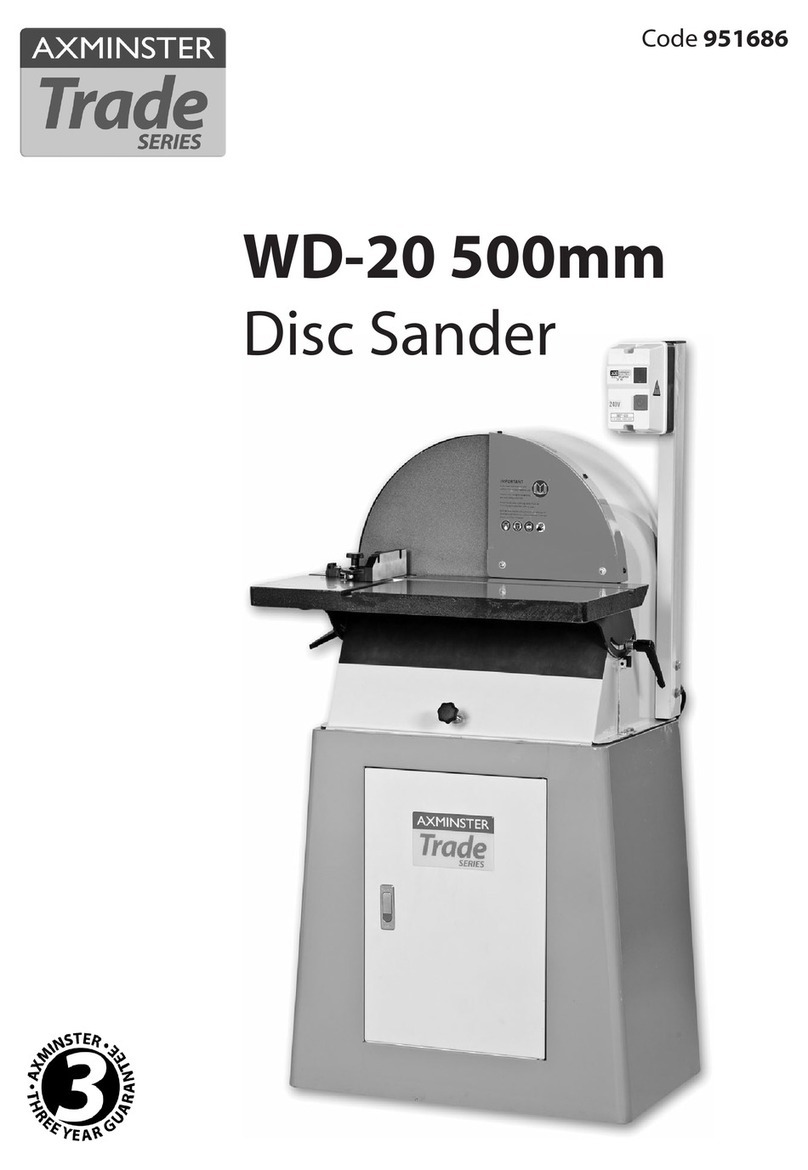
Axminster WD-20 User manual

Axminster

Axminster WD-20 User manual

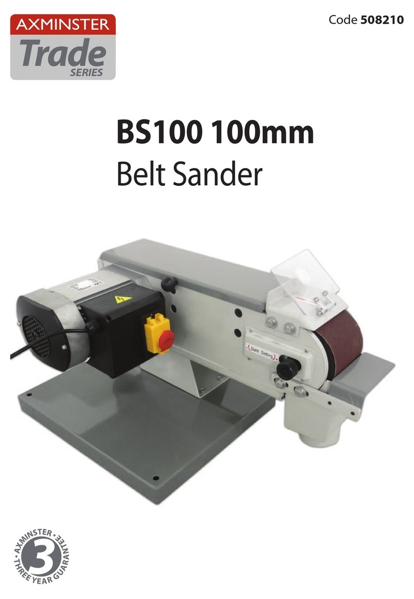
Axminster BS100 User manual

Axminster

Axminster BS100 User manual

Popular Sander manuals by other brands

Makita 9910 instruction manual

Makita

Makita 9910 instruction manual

AEG EX 125 ES Original instructions

AEG

AEG EX 125 ES Original instructions

American Sanders Alto Classic 8 Operator's manual

American Sanders

American Sanders Alto Classic 8 Operator's manual

Charnwood DS10 owner's manual

Charnwood

Charnwood DS10 owner's manual

Makita BO6040 instruction manual

Makita

Makita BO6040 instruction manual

VONROC PM505AC Original instructions

VONROC

VONROC PM505AC Original instructions

NEKTRA 6170087 user guide

NEKTRA

NEKTRA 6170087 user guide

Makita BO6040 instruction manual

Makita

Makita BO6040 instruction manual

Clarke COS210 Operation & maintenance instructions

Clarke

Clarke COS210 Operation & maintenance instructions

Porter-Cable 121 instruction manual

Porter-Cable

Porter-Cable 121 instruction manual

Bavaria BPO 1100 E Original operating instructions

Bavaria

Bavaria BPO 1100 E Original operating instructions

Dynabrade 57550 manual

Dynabrade

Dynabrade 57550 manual

Sparky Group MBS 1100 Original instructions

Sparky Group

Sparky Group MBS 1100 Original instructions

eisenblatter VARILEX High Torque Original instructions

eisenblatter

eisenblatter VARILEX High Torque Original instructions

Genesis GPS2303 Operator's manual

Genesis

Genesis GPS2303 Operator's manual

Makita BO5030 instruction manual

Makita

Makita BO5030 instruction manual

Kalamazoo S6MV manual

Kalamazoo

Kalamazoo S6MV manual

Universal Tool UT8701 operating instructions

Universal Tool

Universal Tool UT8701 operating instructions

manuals.online logo
manuals.online logoBrands
  • About & Mission
  • Contact us
  • Privacy Policy
  • Terms and Conditions

Copyright 2025 Manuals.Online. All Rights Reserved.