Axonics SNM System 2501 User manual

1
1
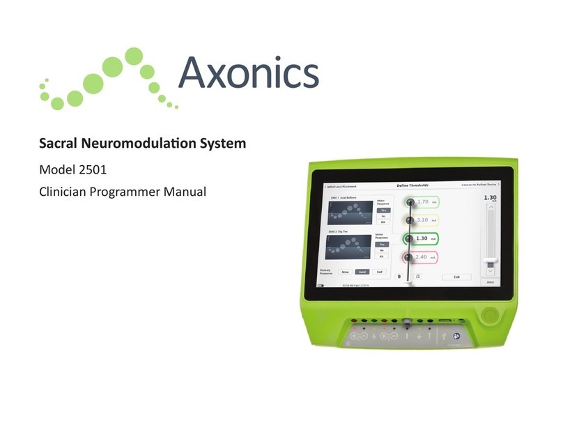
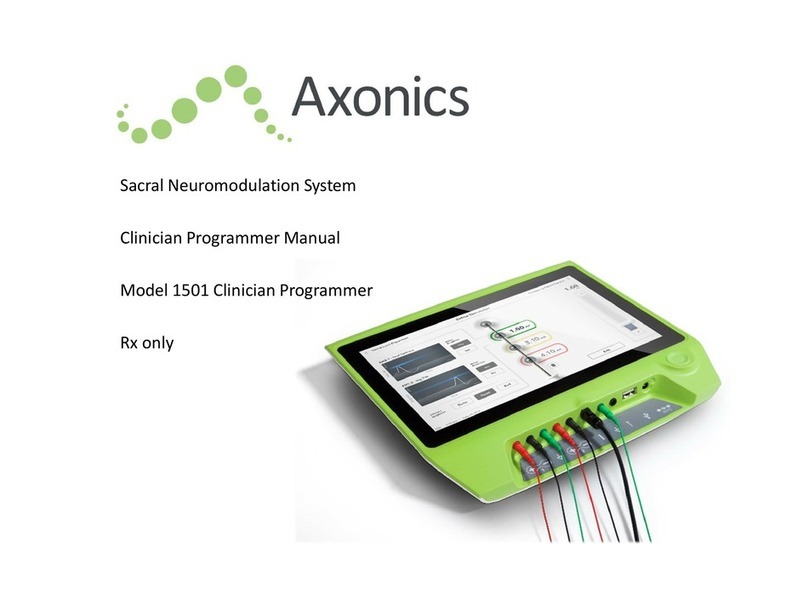
Sacral Neuromodulation System
Clinician Programmer Manual
Model 2501 Clinician Programmer
Rx only

2
Axonics®, Axonics Modulation®, Axonics Modulation Technologies®, Axonics Sacral
Neuromodulation System® and r-SNM® are trademarks of Axonics Modulation Technologies, Inc.,
registered or
pending registration in the U.S. and other countries.
Refer to the appropriate clinician manuals for additional information on the Axonics SNM System,
including contraindications, warnings, precautions, adverse events, individualization of treatment,
patient selection, and implant procedures.

Table of Contents
3
Introduction .................................................................................................................................................................6
Purpose of the trial system ...........................................................................................................................................6
Axonics SNM System for Bowel Control ........................................................................................................................7
Indications................................................................................................................................................................................................7
Precautions ..............................................................................................................................................................................................7
Contraindications .....................................................................................................................................................................................7
Precautions ..................................................................................................................................................................8
Parameter adjustment.............................................................................................................................................................................8
Sensitivity to stimulation .........................................................................................................................................................................8
Programmer interaction with flammable atmospheres..........................................................................................................................8
Programmer interaction with other active implanted devices ...............................................................................................................8
Telemetry signal disruption from EMI .....................................................................................................................................................8
Device Specifications ..................................................................................................................................................10
Operating characteristics .......................................................................................................................................................................10
Storage and Usage Environment ...........................................................................................................................................................10
Maintenance ..........................................................................................................................................................................................11
Handling and disposal ............................................................................................................................................................................11
Wireless Communication .......................................................................................................................................................................12
Start Up and General Functions...................................................................................................................................14
Summary of Clinician Programmer Buttons and Connections ..............................................................................................................15
Turning the Clinician Programmer On and Off ......................................................................................................................................16

Table of Contents
4
Logging-in to the Clinician Programmer ................................................................................................................................................17
Navigating the Home Screen .................................................................................................................................................................18
Description of Battery Level Icons and Charging...................................................................................................................................19
Introduction to Clinician Programmer Prompts ....................................................................................................................................20
Understanding Impedance Values.........................................................................................................................................................21
Controlling Stimulation Amplitude ........................................................................................................................................................22
Test Stimulation During Lead Implantation .................................................................................................................26
Foramen Needle Test Stimulation .........................................................................................................................................................27
PNE Lead Test Stimulation.....................................................................................................................................................................30
Tined Lead Test Stimulation ..................................................................................................................................................................33
Programming the stimulator .......................................................................................................................................36
Connecting to a stimulator ....................................................................................................................................................................37
Patient Device Screen Overview............................................................................................................................................................39
Setting up a New Stimulator..................................................................................................................................................................40
Viewing the Status of a Stimulator ........................................................................................................................................................43
Resetting the Stimulator........................................................................................................................................................................50
Programming the Stimulator Stimulation Settings................................................................................................................................51
Home Screen Tools ......................................................................................................................................................58
User Account Management...................................................................................................................................................................58
Clinician Programmer Settings...............................................................................................................................................................59
Programming Session Reports...............................................................................................................................................................62
Troubleshooting..........................................................................................................................................................64
Issues with the CP display ......................................................................................................................................................................64

Table of Contents
5
Issues Communicating with a Stimulator ..............................................................................................................................................65
Issues delivering stimulation .................................................................................................................................................................66
Impedance Issue during lead implant....................................................................................................................................................69
Impedance Issue with the Stimulator ....................................................................................................................................................70
Label Symbols .............................................................................................................................................................71

Introduction
6
Introduction
This manual provides information about the Model 2501 Axonics Sacral Neuromodulation (SNM) System Clinician
Programmer (CP). The CP can be used during implantation and programming of the following Axonics SNM
System components:
Axonics Model 1601 Trial Stimulator
Axonics Model 1901 PNE Lead
Axonics Model 2201 Tined Lead
Purpose
The CP can provide test stimulation during lead implantation and can wirelessly communicate with the
Trial
Stimulator to check device status and program the device.
Note: The CP is required to implant a lead or program a Trial Stimulator for an external trial of SNM. Confirm
the availability and operation of a CP prior to beginning a lead implant procedure.
Note: The Model 2501 Clinician Programmer only communicates with the Trial Stimulator (Model 1601). It
does not communicate with the implanted Neurostimulator (Model 1101). Use the Model 1501 Clinician
Programmer to communicate with the Neurostimulator and to implant a permanent tined lead.
Package Contents
Axonics Model 2501 Clinician Programmer
Power Supply
Product Literature
Caution: Do not sterilize any part of the Clinician Programmer. Sterilization may damage the
programmer
Purpose of the trial system
The Axonics SNM Trial System is used for a test period to evaluate if a subject should be treated with the Axonics SNM
System.

Axonics SNM System for Bowel Control
7
Axonics SNM System for Bowel Control
Indications
Axonics SNM Therapy for bowel control is indicated for the treatment of chronic fecal incontinence in patients who
have failed or are not candidates for more conservative treatments.
Precautions
Clinician Training
Implanting clinicians should be trained on the implantation and use of the Axonics SNM System.
Prescribing clinicians should be experienced in the diagnosis and treatment of fecal incontinence and
should be trained on the use of the Axonics SNM System.
Use in Specific Populations
The safety and effectiveness of this therapy has not been established for:
Pregnant women
Pediatric use (patients under the age of 18)
Patients with progressive, systemic neurological diseases
Bilateral stimulation
Contraindications
The Axonics SNM System is contraindicated for the following patients
•Patients who have not demonstrated an appropriate response to test stimulation; or
•Patients who are unable to operate the Axonics SNM System.

Precautions
8
Precautions
Parameter adjustment – The steps below should be taken to prevent sudden stimulation changes that lead to an
uncomfortable jolting or shocking feeling:
Stimulation parameters should be changed in small increments.
The stimulation amplitude should be allowed to ramp to full amplitude slowly.
Before disconnecting a stimulation cable or turning stimulation on or off, the stimulation amplitude should be
decreased to 0.0 mA.
Sensitivity to stimulation – Some patients, especially those that are very sensitive to stimulation, may be able to sense
the telemetry signals associated with the CP communicating with the Stimulator.
Programmer interaction with flammable atmospheres – The CP is not intended to be used in the presence of a
flammable gases, and the consequences of using the CP in such an environment is not known.
Programmer interaction with other active implanted devices – When a patient has a Stimulator and an active
implanted device (for example, a pacemaker, defibrillator, or another Stimulator), the RF signal used to program any
of these devices may reset or reprogram the other devices.
Whenever the settings for these devices are changed, a clinician familiar with each device should check the program
settings of each device before the patient is released (or as soon as possible). Patients should contact their physician
immediately if they experience symptoms that are likely to be related to the devices or their medical condition.
Telemetry signal disruption from EMI – The Stimulator should not be programmed near equipment that may
generate
electromagnetic interference (EMI) as the equipment may interfere with the CP’s ability to communicate with the
Stimulator. If EMI is suspected to be interrupting programming, the CP and the Stimulator should be
moved away from
the likely source of EMI.
Unintended use – The CP is intended for use during implantation and programming of the Axonics SNM System. It should
only be used with manufacturer provided accessories. Do not use the CP for stimulation or other purposes not described
in this manual. Unintended use can result in user or patient injury.
Accidental electrode contact – Avoid accidental contact between connected but unapplied electrodes and other
conductive parts, including those connected to protective earth.

Warnings
9
⚠Warning: Do not attempt to modify or service this product. If there is an issue with the product, please consult an Axonics
representative.
⚠Warning: Shortwave diathermy, microwave diathermy, or therapeutic ultrasound diathermy (collectively described as
diathermy) should not be used during implantation of the Axonics SNM System or on patients implanted with the Axonics
SNM System. Diathermy can transmit energy through the CP and accessories or the implanted system, potentially causing
tissue damage at the location of the surface or implanted electrodes, resulting in severe injury.

Device Specifications
10
Device Specifications
Operating characteristics
Power source: Lithium-ion battery (rechargeable)
External power source: Powerbox EMX30
Input Power: 100 – 240 VAC, 47 – 63 Hz, 0.3 - 0.6 A
Output Power: 15 V, 2 A
Battery life*: 3 hours per charge; 5-years expected lifetime
Dimensions: 257 mm (w) x 246 mm (h) x 22 mm (d) Weight: 1125 g
Material:
Housing: Polycarbonate and ABS resin blend
Buttons: Silicone with polyurethane coating
Screen: Touch-screen, LCD display, 1280 x 800 pixels
CP Test Stimulation Output:
Maximum Amplitude: 12.5 mA
Frequency: 14 Hz
Pulse width: 210 μs
*Note:
Battery life may vary depending on frequency of use
Storage and Usage Environment
Usage Environment
The following lists the appropriate temperature, humidity, and pressure condition for use of the Axonics CP:
Temperature: 5 °C to 35 °C
Humidity: 15% to 95%
Pressure: 70 kPa to 106 kPa

Device Specifications
11
Shipping and Storage environment
The following lists the appropriate temperature, humidity, and pressure condition for shipping and storage of the Axonics
CP:
Temperature (short term: 3 days): -25 oC to 70 oC
Temperature (long term): 20 oC to 30 oC
Humidity (short term: 3 days): 15% to 95%
Humidity (long term): 30% to 85%
Pressure (short term: 3 days): 57 kPa to 106 kPa
Pressure (long term): 70 kPa to 106 kPa
If the CP is exposed to extreme temperatures, it may be permanently damaged and should not be used, even if it
has returned to a temperature that is within the specified operating range.
Maintenance
At least once a year, the CP should be inspected for visible damage and should be charged and powered on to
confirm the Log-In screen is still accessible. Significant physical damage or an inability to power on the device should
be reported to the manufacturer and the device should not be used.
Handling and disposal
Cleaning: The CP can be wiped with a cloth lightly moistened with water. No other cleaning agents should be used.
Replacement: If the CP is lost or not working, contact Axonics.
Disposal: Do not incinerate the CP as the battery may explode. If the CP is no longer needed, contact Axonics to
return the device.

Device Specifications
12
Wireless Communication
Radiofrequency telemetry
Model: 2501
IC: 20225-C
FCC ID: 2AEEGC
Quality of Wireless Service:
This device operates in the 401-406 MHz frequency and the maximum effective radiated power is below the
limit of 25 µW ERP/EIRP as specified in EU: EN ETSI 301-839 and EN ETSI 302-537 and USA: FCC 47 CFR Part
95; Subpart I. The CP has to be within 1 meter from the Stimulator for successful communication.
Wireless Security:
Any CP can communicate with a Stimulator. Additional mechanisms exist to ensure the integrity of radio data.
FCC Compliance
This device complies with part 15 of the FCC Rules. Operation is subject to the following two conditions: (1) This device
may not cause harmful interference, and (2) this device must accept any interference received, including interference
that may cause undesired operation.
This transmitter is authorized by rule under the Medical Device Radio communication Service (in part 95 of the FCC
Rules) and must not cause harmful interference to stations operating in the 400.150–406.000 MHz band in
the Meteorological Aids (i.e., transmitters and receivers used to communicate weather data), the Meteorological
Satellite, or the Earth Exploration Satellite Services and must accept interference that may be caused by such stations,
including interference that may cause undesired operation. This transmitter shall be used only in accordance with the
FCC Rules governing the Medical Device Radio Communication Service. Analog and digital voice communications are
prohibited. Although this transmitter has been approved by the Federal Communications Commission, there is no
guarantee that it will not receive interference or that any particular transmission from this transmitter will be free from
interference.
Note: FCC Compliance information can be accessed on the CP in the Clinician Programmer Settings screen.
IC Compliance
This device complies with Industry Canada license-exempt RSS standard(s). Operation is subject to the following two
conditions: (1) this device may not cause interference, and (2) this device must accept any interference, including
interference that may cause undesired operation of this device.

Device Specifications
13
FCC and IC Compliance
This device may not interfere with stations operating in the 400.150–406.000 MHz band in the Meteorological Aids,
Meteorological Satellite, and Earth Exploration Satellite Services and must accept any interference received, including
interference that may cause undesired operation.
Note: Changes and modifications to the Clinician Programmer are not authorized by Axonics and could void FCC and
IC certification and negate the user’s authority to use the product.
Note: The USB port on Clinician Programmer is used for the purpose of transferring (copying) the session reports to a USB
flash drive. Do not plug any other devices into this port. Some examples of devices that are prohibited are: USB with WiFi or
Bluetooth, USB Data Transfer Cable, USB mouse, USB keyboard, or USB flash drives with autorun executables.
Note: The USB port is disabled in all screens except, Reports List screen (see section Programming Session Reports). In this
screen the session reports can be transferred to a USB flash drive. In the Reports List screen, the stimulation functions are
not accessible and are disabled. The reports are transferred (copied) in PDF format.
Note: A Wireless connection through the USB port is not an intended use. This wireless functionality is disabled in the
Clinician Programmer.

14
Start Up and General Functions
This section describes the process of starting up the Clinician Programmer (CP) and provides instructions on several key
CP functions that are encountered in multiple screens when using the CP.
The following sections include:
• Getting Started
• Summary of CP Buttons and Connections
• Turning the CP on and off
• Logging-in to the CP
• Navigating the Home screen
• General functions
• Description of Battery Level Icons and Charging
• Introduction to Clinician Programmer Prompts
• Understanding Impedance Values
• Controlling Stimulation Amplitude

Summary of CP Buttons and Connections
15
Summary of Clinician Programmer Buttons and Connections
The CP has two physical buttons:
①Power Button – turns the CP on and off.
②Stimulation Button – turns test stimulation o
n and off
(select screens only)
The CP has a Connector Panel with plugs for the cables
that are used with the CP. The symbols on the Connector
Panel indicate which cable should be used with each
plug:
③Not Used
④Not Used
⑤Not Used
⑥Tined Lead Test Stimulation
⑦Stimulation Ground
⑧Foramen Needle Test Stimulation
⑨Power Input
⑩USB port
The purposes and uses of these buttons and co
nnections
are described throughout this manual.
Note: EMG functionality (③, ④, ⑤) is not available in
this model of the Axonics Clinician Programmer.
Note: The USB port is disabled in all screens, except
Reports List Screen (see section Programming Session
Reports).

Turning the Clinician Programmer On and Off
16
Turning the Clinician Programmer On and Off
Turning on the CP
•Press and hold the power button (①) to turn
on the
CP.
•The CP screen will show the Axonics logo as
the CP
starts up.
•The CP will proceed to the password protected
Log-In
screen.
Turning off the CP
•From any CP screen, press and hold the power
button (①) to turn off the CP.

Logging-in to the Clinician Programmer
17
Logging-in to the Clinician Programmer
1
2 3 4
• When the CP is turned on, it
will start-up at the Log-In
screen.
• By default, the “ADMIN” user
name will appear on the Log-
In screen (①).
• Press “ADMIN” to log in
using that user name.
• Press the down arrow to the
right of the user name to
select a different user name (
②). There will not be a down
arrow if no additional user
names exist.
4
• A short list of names will
appear when the down arrow is
pressed.
• Press a user name to select it to
log in (③).
• More names can be accessed
by scrolling up and down the
list using the arrows on the
right (④).
5
• A key pad will appear when a
user name is selected.
• Enter the 4-digit passcode
associated with the selected
user name to log-in to the CP.
• Press “Cancel” to switch user
names(⑤).
Note: The CP will automatically log-out a user after 30 minutes of inactivity.

Navigating the Home Screen
18
Navigating the Home Screen
The Home screen will appear after successful log-in to the CP.
The Home screen provides access to the main functions of
the CP, including:
① Lead Placement – Deliver test stimulation during a lead
placement procedure.
② Connect to Patient Device – Check the status of and
program a Stimulator.
③ CP Settings - Change CP settings, including default
stimulation settings.
④ Reports List - View, save, and manage CP reports.
Additional information about each of these functions is
included in the following sections of this manual.
⑤,⑥These buttons are for use by the
Manufacturer only.

Description of Battery Level Icons and Charging
19
Description of Battery Level Icons and Charging
Determining the CP battery level
The battery icon shows the CP battery level. This icon is always displayed in the bottom left
corner of the screen when the CP is on.
The number of bars on the battery icon indicates the CP battery level, and bars
disappear from right-to-left as battery charge is depleted. The battery levels show on this
page are as follows:
①Partially Full to Full (2 to 4 bars)
• When 4 bars are present the battery is full or nearly full. At 4 or 3 bars, the battery
bars are white. When the battery drops to 2 bars, the bars are yellow indicating
less than half the battery charge is remaining.
②Low
•When the battery level is low, the battery displays 1 red bar. Note: A procedure
should not be started with a low battery to avoid the CP battery dying during the
procedure.
• Two minutes before the CP automatically shuts down due to a critically low
battery, the user will be prompted to charge the CP. This prompt can only be
disabled by plugging in and charging the CP.
③Charging
• When the device is charging, the battery icon shows 4 green bars and a lightning
bolt. Charging a fully depleted CP can take up to 6 hours.
How to Charge the CP
To charge the CP, plug the power supply into a power outlet and into the CP (④). The
power supply plugs into the CP at the right end of the Connection
Panel and is indicated by the “Refer to manual” symbol
Note: Charge the CP after each use. A full battery should last for approximately
3-4 hours of use. If multiple implant procedures are
scheduled on a single day, charge the CP between procedures to ensure the battery does not run out. Always keep the CP power supply
with the CP.
Note: The CP should provide 5 or more years of service. With repeated charging, the CP battery may lose capacity. Notify Axonics if
you experience a significant change in the operating time for a fully charged CP battery.

Introduction to Clinician Programmer Prompts
20
Introduction to Clinician Programmer Prompts
Prompts will present information during CP use in order
to
confirm user intent and to provide information on action
progress and errors. Each prompt presents the
following
information:
①Prompt type – An icon indicating the general purpose of
the prompt (e.g., progress indicator, error alert)
②Headline – The general topic of the prompt
③Message – A statement of the reason for the prompt
④Response button(s) – A button or buttons appear for
prompts which require a response from the user
Types of Prompts
An icon will be part of each prompt to indicate the purpose of the prompt. Icons include:
Prompt Purpose Prompt Icon
Query Requires confirmation to proceed in situations where inputs may
result in
system performance issue or disruption in the workflow. If applicable, the
Progress Prompt will appear after input.
Progress
Prompt
A momentary display appears to confirm the progress and completion
of a task. No action required.
Error A device issue has occurred, compromising device function. This issue may or
may not be reversible.
CP Failure A serious Clinician Programmer issue has occurred, compromising device
function. The Clinician Programmer will automatically shut down. User may
restart Clinician Programmer to see if issue persists.
Other manuals for SNM System 2501
2
Table of contents
Other Axonics Medical Equipment manuals
Popular Medical Equipment manuals by other brands

Infra-Slim
Infra-Slim BODY SHAPING SYSTEM Manual Instrucitons

Drive DeVilbiss
Drive DeVilbiss Sidhil 1006100001 user manual

Pressalit Care
Pressalit Care R8122 Mounting instruction

Welch Allyn
Welch Allyn CP 50 Updating Software

Hanger
Hanger ACP MEGAPULSE II user manual

Molift
Molift Etac Nova Stand Up user manual