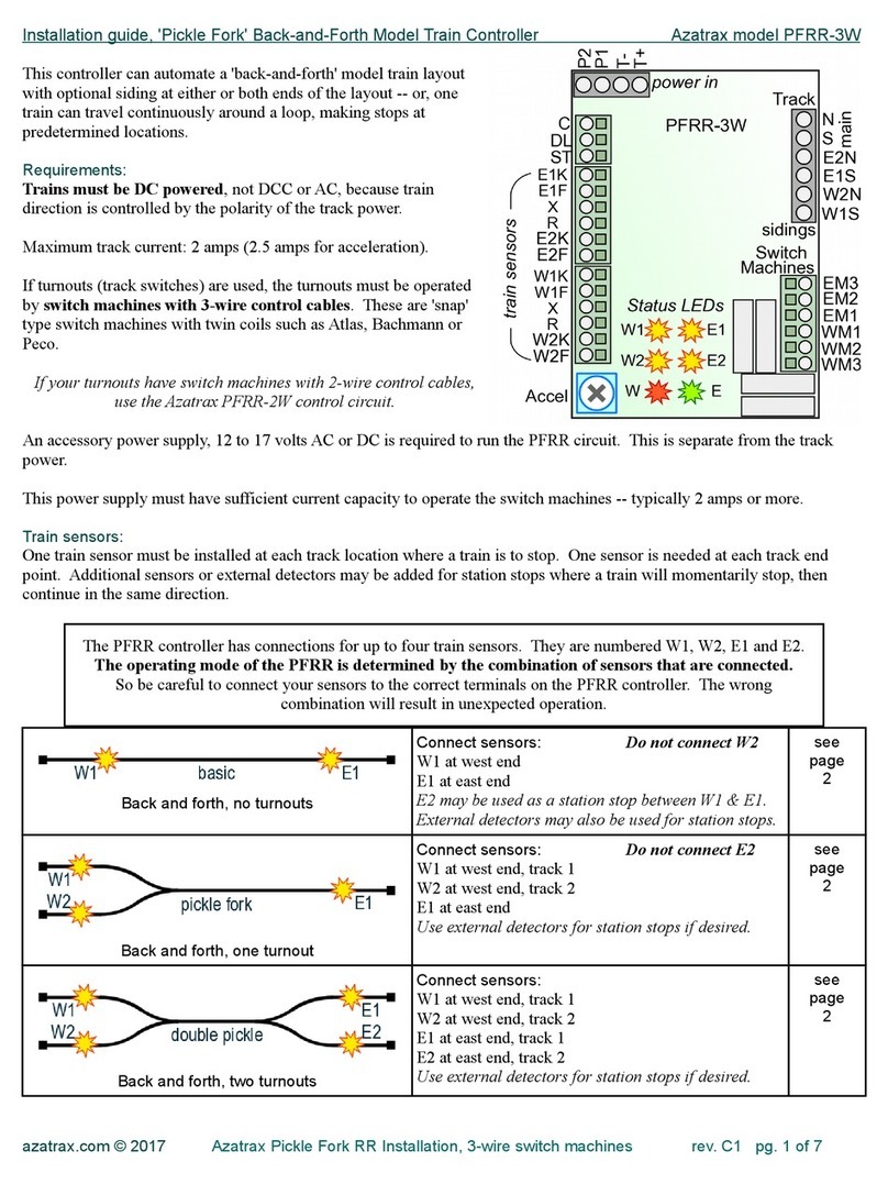
Azatrax TS2 User manual

Installation Guide Azatrax Model Railroad Track Signal Control - Single Track TS2
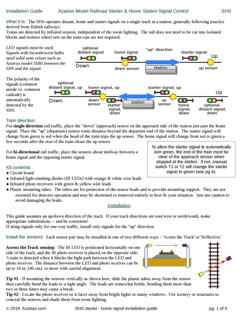
What it is: The TS2 operates one or two trackside block signals (one in
each direction) on one track to simulate the block signals of a real railroad.
Trains are sensed at the signal location using infrared sensors, independent
of the room lighting. The TS2 does not require the rail to be cut into
isolated blocks and does not require resistor wheel sets on the train cars.
Multiple TS2 units may be linked together so that successi e block signals
along the track will be properly coordinated.
LED signals must be used. Signals with incandescent bulbs need solid
state relays such as Azatrax model SSR6 between the TS2 and the signal.
Most types of LED block signals may be used. The polarity of the signals
(common anode s. common cathode) is automatically detected by the TS2.
Li itations: The TS2 only senses trains as they pass the block boundary. Two TS2's, one at each end of a block, tell each
other when a train enters or lea es a block, so they can deduce when the block is occupied or clear. Because the TS2 does
not actually sense the physical presence of a train in the block, it can gi e false indications if part of a train becomes
uncoupled and is left behind in the block, or if a train enters or lea es the block by some route other than the two ends that
are monitored by the TS2's. To compensate for this, see 'Interlocking Functions' on pg. 5.
Kit contents:
★ Circuit board
★ Infrared light-emitting diodes (IR LEDs) with orange & white wire leads
★ Infrared photo recei ers with green & yellow wire leads
★ Plastic mounting tubes. The tubes are for protection of the sensor leads and to pro ide mounting support. They are not
essential for detector operation and may be shortened or remo ed entirely to best fit your situation. Just use caution to
a oid damaging the leads.
★ 1,000 ohm resistor for interlocking functions (pg. 5)
★ Mounting screws
Installation
This guide assumes an east/west direction of the track.
Install the sensors: Choose a location for the signals.
If using only one signal for one-way traffic, install only
the east-bound signal. Each sensor pair may be installed
in one of two different ways - 'Across the Track' or
'Reflecti e.'
Across the Track sensing: The IR LED is positioned horizontally on one
side of the track, and the IR photo recei er is placed on the opposite side.
A train is detected when it blocks the light path between the LED and
photo recei er. The distance between the LED and photo recei er can be
up to 18 in. (46cm), or more with careful alignment. Placing the sensors at
an angle across the track a oids possible detector flickering caused by the
gaps between cars.
Tip #1 - If mounting the sensors ertically as shown here, slide the plastic tubes away from the sensor
then carefully bend the leads to a right angle. The leads are somewhat brittle, bending them more than
two or three times may cause a break.
Tip #2 - Locate the photo recei er so it faces away from bright lights or sunny windows. Use scenery or structures to
conceal the sensors and shade them from room lighting.
© 2019 Azatrax.co TS2 installation guide - single track pg. 1 of 6
west
sensor
W E
westbound
signal
east
sensor
eastbound
signal
35 - 50 scale ft
(10 - 16 scale m)
east link
west bound
signal east bound
signal
config
jumpers
LE
C
SE
EK
EF
X
P1
P2
G
Y
R
M
Rtn
Rtn
M
R
Y
G
+G
+R
4a
power
TS2
R
WK
WF
SW
C
LW
west stop
east
sensor
west
sensor
west link
W E
east stop

Reflective sensing: Trains are detected when light from the IR LED is
reflected off a train and sensed by the IR photo recei er. Typically the
sensors are mounted in two 3/16-inch (4.8mm) holes drilled in the
roadbed as shown here. Vertical installation works for S and larger scales
as long as there is no structure abo e the track such as a bridge.
Angling the IR LED and photo recei er toward each other is best for N
and HO scale where the trains are close to the rail head, and in places
where an object abo e the track might otherwise cause false detections.
Angle the IR LED and photo recei er so their centerlines intersect at the height of the bottom of your rolling stock.
Tip #3 - You can ballast your track after sensors are installed. Co er each sensor with a bit of transparent tape. Apply
ballast. When the glue has dried use a dental pick or similar tool to remo e ballast from the sensors. An opening of
just 1 or 2 mm is required.
Connecting wires to the terminal locks: The TS2 has 'spring cage' quick-connect terminal blocks.
♣ Strip 3/8 inch (1 cm) of insulation off the end of the wire.
♣ Use a small screwdri er to push down (push, do not turn) the terminal's button. Push firmly.
♣ While the button is pushed in, hold the wire at a 45 degree angle to the terminal block and push it in.
About 3/8 inch of wire should go into the terminal block.
♣ Release the button. Tug on the wire to make sure it is secure.
hen two wires are connected to the same terminal, twist the bare ends of the wires together.
Connect east sensor pair: Connect the orange wire from the IR LED to terminal EK. Connect the green wire from the IR
photo recei er to terminal EF. Now, how you connect the white and yellow wires to the TS2 will determine whether the east
detector will operate in 'Across the Track' or 'Reflecti e' mode. See the diagrams below:
Connect west sensor pair: Connect the orange wire from the IR LED to terminal WK. Connect the green wire from the
IR photo recei er to terminal WF. As with the east sensor, how you connect the white and yellow wires will determine
whether the west detector will operate in 'Across the Track' or 'Reflecti e' mode. The two detectors may operate in the same
mode or in different modes.
When both sensor pairs are connected, there will be two yellow (or white) wires in 'X' and two white (or yellow) wires in 'R.'
Additional wire may be spliced to the sensor leads if needed. Use similar twisted pair wire for total length up to 26 ft (8m).
➽ Pairing is important! The IR LED that is connected to EK must be paired on the layout with the IR photo recei er that
is connected to EF. The IR LED that is connected to WK must be paired with the IR photo recei er that is connected to WF.
Connect power to the TS2: Connect an accessory power supply of 8 to 16 olts AC or DC to terminals P1 & P2. The red
and yellow ('E' and 'W') LEDs will briefly flash to show that power is on and the circuit is working.
© 2019 Azatrax.co TS2 installation guide - single track pg. 2 of 6

Test and adjust the sensors:
With no trains near either sensor pair, the 'E' and 'W' LEDs on the TS2 module should be off. If either LED is on, correct the
false sensing condition.
To fix false sensing for Across-the-Track mode:
1. Verify that the sensor pair is wired correctly.
2. Make sure the IR LED and photo recei er are pointed at each other, and nothing is between them.
3. Shade the photo recei er from bright lights, and point it away from windows or other strong light sources.
4. Change the nearby room light from incandescent to a fluorescent or LED bulb if possible.
To fix false sensing for Reflective mode:
1. Verify that the sensor pair is wired correctly.
2. Pull the IR LED and photo recei er a bit deeper into the roadbed.
3. Infrared light may be 'leaking' through the roadbed material from the IR LED to the photo recei er. Push a metal shim,
such as the tip of a hobby knife blade, ertically into the roadbed between the IR LED and photo recei er.
4. Is there an object abo e the sensor, such as a bridge, or an upper layout le el? Mount the IR LED and photo recei er at a
shallower angle, or paint the object flat black. Or use across-the-track sensing.
Are all detectors now off? Now test for train detection. Place a locomoti e or car at the east sensor. The 'E' (red) LED
should light. If the yellow LED also lights, re-adjust the west sensor pair for false detection (see abo e).
If the 'E' LED does not light, correct the east sensor pair for a false clear condition.
To fix a false clear indication for Across-the-track mode:
1. Verify that the sensor pair is wired correctly.
2. Adjust the sensor height so the train is fully blocking the light path from the IR LED to the photo recei er.
To fix a false clear indication for Reflective mode:
1. Verify that the sensor pair is wired correctly.
2. Adjust the sensors higher or lower in the roadbed.
3. A bright light source abo e and to the side of the track may be saturating the IR photo recei er. Try pulling it deeper into
the roadbed or create shade with scenery or a structure. Change the nearby light from incandescent to a fluorescent bulb.
Test with se eral types of rolling stock and adjust the sensors as needed.
Remo e the train from the east detector, make sure the 'E' LED goes out.
Place a train at the west detector. The 'W' (yellow) LED should light. If the 'E' LED also turns on, adjust the east sensor
pair for false detection (see abo e).
If the 'W' LED does not light, adjust the west sensor pair for a false clear condition (same process as abo e for the east
sensor pair).
Sensors must be working correctly before continuing the installation.
Configuration ju pers
Two configuration jumpers (small rectangular connector blocks, or 'shunts') are supplied with the
TS2. Three pairs of pins can accept these jumpers. To enable a configuration feature, place a
jumper on both of the pins. To disable a feature, remo e the jumper or park it on one pin.
Yellow adjust jumpers are only for searchlight signals with one bi-color (red/green) LED. To
produce a yellow color, the red and green internal LED chips are illuminated together. The quality
of the 'yellow' light is ariable, depending on the iewing angle, ambient light and the LED itself.
+G: If the 'yellow' color looks too reddish, place a jumper across the +G pins to increase the green intensity.
+R: If the 'yellow' color looks too greenish, place a jumper across the +R pins to increase the red intensity.
A 'middle' yellow is produced when both jumpers are off.
4a: A jumper across this pair of pins enables four aspect signaling (clear / ad ance approach / approach / stop).
Remo ing the 4a jumper selects three aspect signaling (clear / approach / stop).
Signal Connections
The following types of signals may be used with the TS2:
© 2019 Azatrax.co TS2 installation guide - single track pg. 3 of 6

Signal
Operation
2 LEDs 3 LEDs B&O CPL
PRR
bi-color LED
(red/green)
2 aspects green / red green / red green / red ert / horiz green / red
3 aspects not a ailable green / yellow / red green / yellow / red
with or without marker
ert / diag / horiz green / yellow / red
4 aspects not a ailable
green /
flashing yellow /
yellow /
red
green, marker on /
yellow, marker on /
yellow, marker off /
red, marker on
not a ailable
green /
flashing yellow /
yellow /
red
Connect signals to the TS2 according to the diagram below that matches your signals. With ery fine signal wires, it is best
to attach larger wires (AWG #26 or #24, such as found in phone or LAN cable), then insert the larger wire in the terminal
block.
Searchlight (SA) signals that ha e a true red/yellow/green (tri-color) LED connect just like 3-LED signals.
2 aspect green/red
Signals connect
directly to the TS2.
Resistors are
not req ired.
3 or 4 aspect green/yellow/red PRR or B&O
2-wire searchlight signal
2 aspect green/red
operation
2-wire searchlight signal
3 or 4 aspect (green /
yellow / red) operation
3-wire searchlight signal
2 aspect green/red
operation
3-wire searchlight signal
3 or 4 aspect (green /
yellow / red) operation bi-directional signal
For bi-directional signals
with two heads and one
'common' connection
(shown at left),
connect the two 'Rtn'
terminals together.
Note that resistors are not required because resistors are built in to the TS2 circuit board.
If signals are pre-assembled with resistors, first try the signals with their resistors. If the signal lights are too dim, remo e
the resistors.
If an indi idual LED is too bright, a resistor may be wired in series with that LED's wire. Use up to a 1,000 ohm resistor.
Increasing the resistance alue decreases the brightness.
© 2019 Azatrax.co TS2 installation guide - single track pg. 4 of 6

When power is turned on, the TS2 does not know if the block is occupied or not, because a train may ha e been added or
remo ed from the track while power was off. The signals will show 'approach' (yellow) (or red for 2-aspect signals).
Proceed with caution! Normal indications begin once the first train passes the IR sensors.
If the TS2 is not connected to another TS2 circuit down the track to the east or west, it operates in a timed mode. The
track beyond each signal is a ' irtual' block. When a train passes the signal and enters the irtual block, the signal shows a
'stop' aspect (red) to indicate the irtual block is occupied. After a time delay, the signal changes to 'approach' for 3- or 4-
aspect operation, or 'clear' for 2-aspect operation. After another delay the signal changes to the next less restricti e aspect,
and so on until the signal shows 'clear' (green).
Length of the time delay depends on train speed. Fast trains cause shorter time delays because they would clear successi e
blocks faster than slow trains. The minimum delay is 7 seconds, the longest delay is 14 seconds.
The TS2 may e linked to other TS2 circuits to the east and west. The TS2 circuits tell each other when they sense a train
entering or lea ing the block between them. When a train enters a block, the block is 'occupied' until a train exits the block.
The block is then considered to be 'clear.'
Connect 'LE' (link east) of one TS2 to 'LW' (link west) of its eastern neighbor. Connect 'C' of one TS2 to 'C' on the other
TS2. Use twisted pair wire such as found in telephone or ethernet ('Cat 5') cable, AWG #26 or #24. To a oid interference
from high power or high frequency currents, keep this wire away from track power and switch machine wiring.
Any number of TS2 circuits may be linked in this way.
Interlocking functions
To force a lock to 'occupied' status e en when no
train is in the block, connect a switch or relay and a
1,000 ohm resistor between the 'Link' terminal (LE for
the east side, or LW for the west side) and the 'C'
terminal.
The switch can be a dispatcher's switch, auxiliary train
detector or a switch linked to a drawbridge, a switch
machine, etc. In this diagram, closing switch S1 will
cause eastbound signal #1 and westbound signal #2 to
show 'stop.' The entire block between TS2 #1 and TS2
#2 will ha e an 'occupied' status.
To manually clear an 'occupied' lock, momentarily connect the 'Link' terminal (LE for the east side, or LW for the west
© 2019 Azatrax.co TS2 installation guide - single track pg. 5 of 6

side) directly to the 'C' terminal. This may need to be done after a train lea es the block through a turnout onto a siding or
branch line, or if it is remo ed from the track by hand. Briefly pressing S2 clears the block between TS2 #1 and TS2 #2.
To force either signal to a 'stop' condition, rather
than for an entire block as shown abo e:
♦ Connecting 'SE' to 'C' will force the eastbound
signal to show 'stop.'
♦ Connecting 'SW' to 'C' will force the westbound
signal to show 'stop.'
In this example the east/west main line is crossed by
a north/south track. Closing switches S1& S2 will
set the eastbound and westbound signals to 'stop' to
allow traffic to cross on the north/south track.
Sensors may be placed on opposite sides of the
crossing, or both may be on the same side.
Use with a Dual Head Signal
If the 'M' terminal is not used for a B&O marker lamp or for the middle lamp of a PRR signal, the 'M' terminal can be used
to light an LED on a second signal head.
In some places railroads will mount two signal heads on
one mast, one below the other. The lower signal head can
be used for different purposes depending on location and
situation. It's up to you to decide what information the
second signal head will display to the train crews on your
railroad.
For example – a turnout is to the west of a dual head signal. The
2-light lower signal head indicates the position of the turnout
points.
When the turnout is lined for the main track ('Normal'), the upper
signal head displays the condition of the main track and the lower
head shows red.
When the turnout is lined for the siding ('Re erse'), the upper head
shows red and the lower head shows yellow. The eastbound
signal shows red when the turnout is lined for the siding.
To enable full brightness of the second signal head LED, install a
connecting jumper across the two +G pins or across the two +R
pins. As long as you are not using a bi-color red/green searchlight
signal, the jumper setting will not affect the signal appearance.
The two sets of electrical contacts are linked to the switch machine. These can
be internal contacts such as are built in to Tortoise® and Cobalt® switch
machines, or they can be contacts of a latching relay that operates in parallel
with a 'snap' switch machine.
The contact on the left connects terminal 'SE' and 'SW' to 'C' when the turnout is lined with the siding. This causes the
westbound upper signal head to show 'stop.'
The contact on the right directs power to either the yellow or the red LED in the lower signal head.
© 2019 Azatrax.co TS2 installation guide - single track pg. 6 of 6
west bound
signal
SW
TS2 G
Y
R
Rtn
G
Y
R
Rtn
east bound
signal
M
Electrical contacts linked
to the turnout points.
Contacts are shown in the "nor al" position (N)
with points set for the ain track.
N
N
R
R
SE
C
Table of contents
Other Azatrax Controllers manuals