Interlocking functions
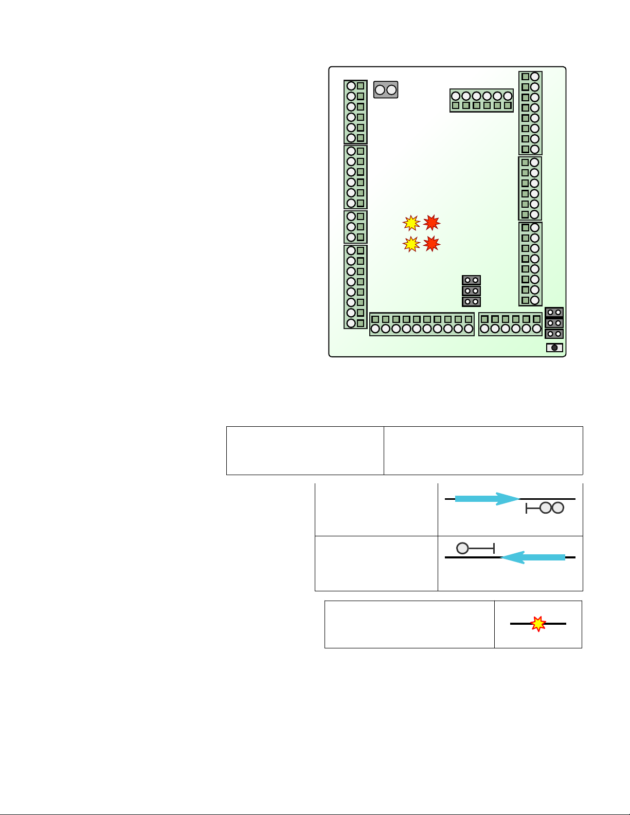
To force a block to 'occupied' status even when no train is
in the block, connect a 1,000 ohm (1k resistor between the
'Link' terminal (L1 - L5 and a 'C' terminal. This can be
connected via a dispatcher's switch, or a switch linked to a
drawbridge, a switch machine, etc.
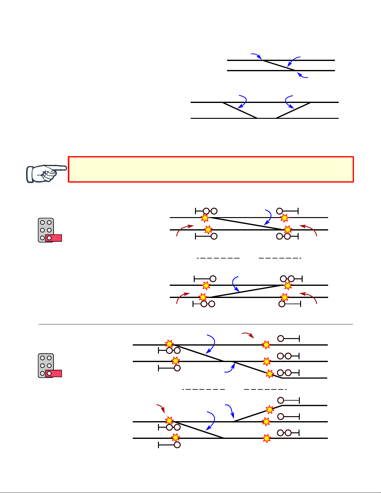
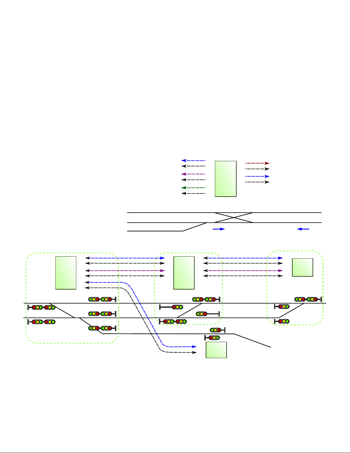
In the example at right, the dashed line is a track block
between TS5 #1 at the west end, and TS5 #2 at the east end.
The red arrows point to the signals at the west and east
entrances to the block. These two signals will show 'stop' if
switch Sw1 is closed ('on' , connecting the 1k resistor across
the Link wire and 'C'.
To manually clear an 'occupied' block, momentarily connect the 'Link' terminal (L1 - L5 directly to a 'C' terminal. This
may need to be done after a train leaves the block through a turnout onto a siding or branch line, or if it is removed from the
track by hand.
In the example above, when Sw2 is momentarily closed, shorting the Link wire to 'C', the two signals indicated by the red
arrows will change to 'clear.'
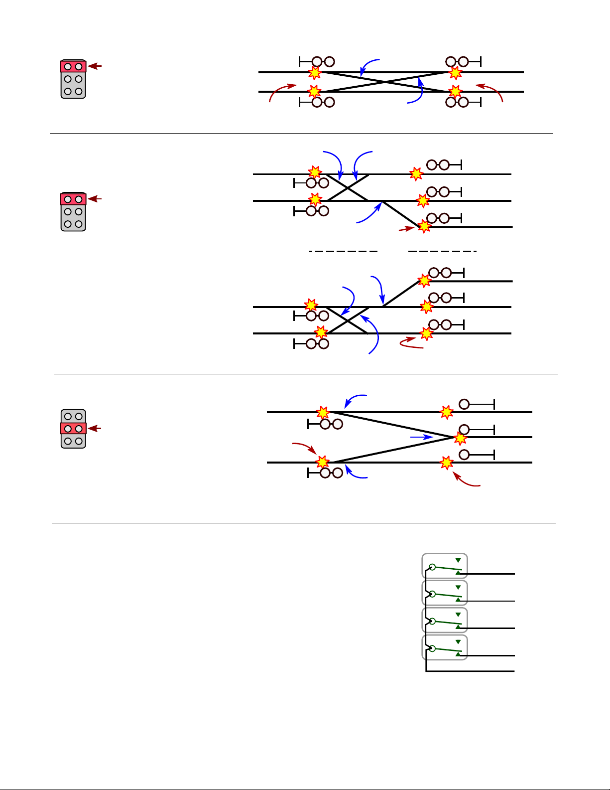
Signal override with Stop inputs
Using Stop inputs S1 - S5, any of the five signals
controlled by a TS5 can be forced to show 'stop', or
restricted to 'approach' or 'diverging approach'
indication. This can be useful when the control
point has turnouts to uncontrolled sidings.
To force Signal 1 to show 'stop', connect terminal
'S1' to any 'C' terminal. To limit Signal 1 to
'approach' for a single-head signal, or 'diverging
approach' for a dual-head signal, connect terminal
'S1' to a 1,000 ohm (1k resistor, and connect the
other end of the resistor to any 'C' terminal.
Use terminal S2 to control Signal 2 in a similar fashion. Use 'S3' for Signal 3, 'S4' for Signal 4, and 'S5' for Signal 5.
In this example, a turnout to an uncontrolled siding is between signals 2 and 4. An electrical contact is linked to the turnout
points. This contact closes ('on' when the turnout is lined for the siding. This connects terminal 'S2' to 'C', causing Signal 2
to show 'stop.' This also connects 'S4' via a 1k resistor to 'C', causing Signal 4 to show 'diverging approach.'
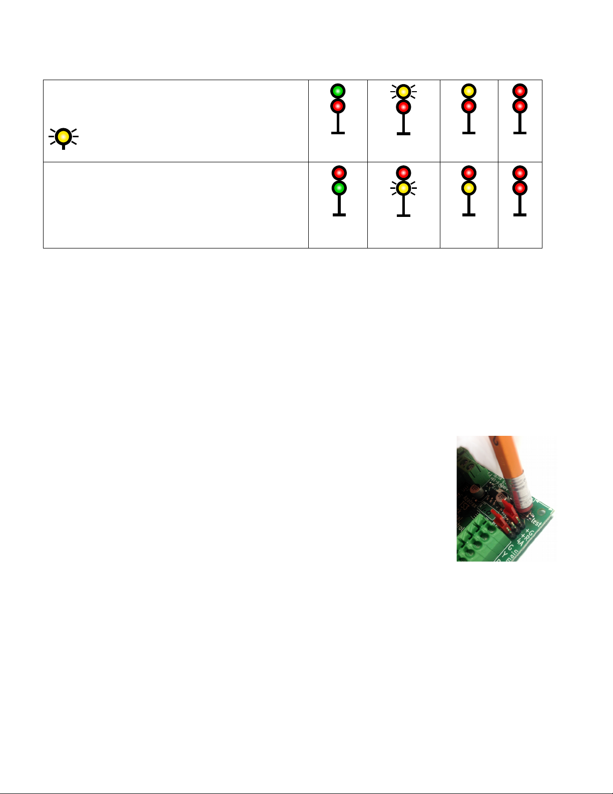
Signal indications and single vs. dual head signals
A single head signal shows track conditions ahead on a single track without turnouts. A 'stop' indication (red means
the track block immediately beyond the signal has a train in it, or an open drawbridge or other hazard. An 'approach'
indication (yellow means it is safe to enter the block, but the following signal is at 'stop,' so slow down and be
prepared to stop at the next signal. If 4-aspect signaling is in use (see the signal config jumpers on page 7 an
'advance approach' indication (flashing yellow means it is safe to enter the block, but the next signal is at
'approach,' so reduce speed accordingly. A 'clear' indication (green means the track ahead is clear and trains may
run at up to the posted speed limit.
Dual-head signals are located where there is an upcoming turnout. A train
may continue on the main line or take a diverging route depending on how
the turnout is lined (Normal vs. Reverse . If the lower head indicates 'stop,'
then the turnout is in the Normal position and the upper head indicates the
condition of the main track ahead. If the upper head indicates 'stop,' then
the turnout is in the Reverse position and the lower head indicates the
© 2019 Azatrax.com TS5 installation guide - control point PRELIMINARY 28 Dec 2019 pg. 9 of 10