AB-7043
3
Model Number
Model number Description
QY5010 Base model number of Display Panel for Model FVY513_J/FVY514_J/FVY515_J
S1000 Power supplied from Model FVY513_J/FVY514_J/FVY515_J
Specifications
Item Specification
Power supply 12 V DC 1 V (supplied from Model FVY513_J/FVY514_J/FVY515_J
Power consumption Max. 0.1 VA
Cable JIS VCTF (0.3 mm2 4 cores) cable
Environmental
conditions
Rated operating
condition*1
Ambient temperature 0 C to 50 C
Ambient humidity 10 %RH to 85 %RH (non-condensing)
Vibration 5.9 m/s2 (10 Hz to 150 Hz)
Transport/storage
conditions
Ambient temperature -20 C to 70 C
Ambient humidity 10 %RH to 85 %RH (non-condensing)
Vibration (storage) 5.9 m/s2 (10 Hz to 150 Hz)
Vibration (transport) 9.8 m/s2 (10 Hz to 150 Hz)
Enclosure rating IEC IP40 (dustproof)
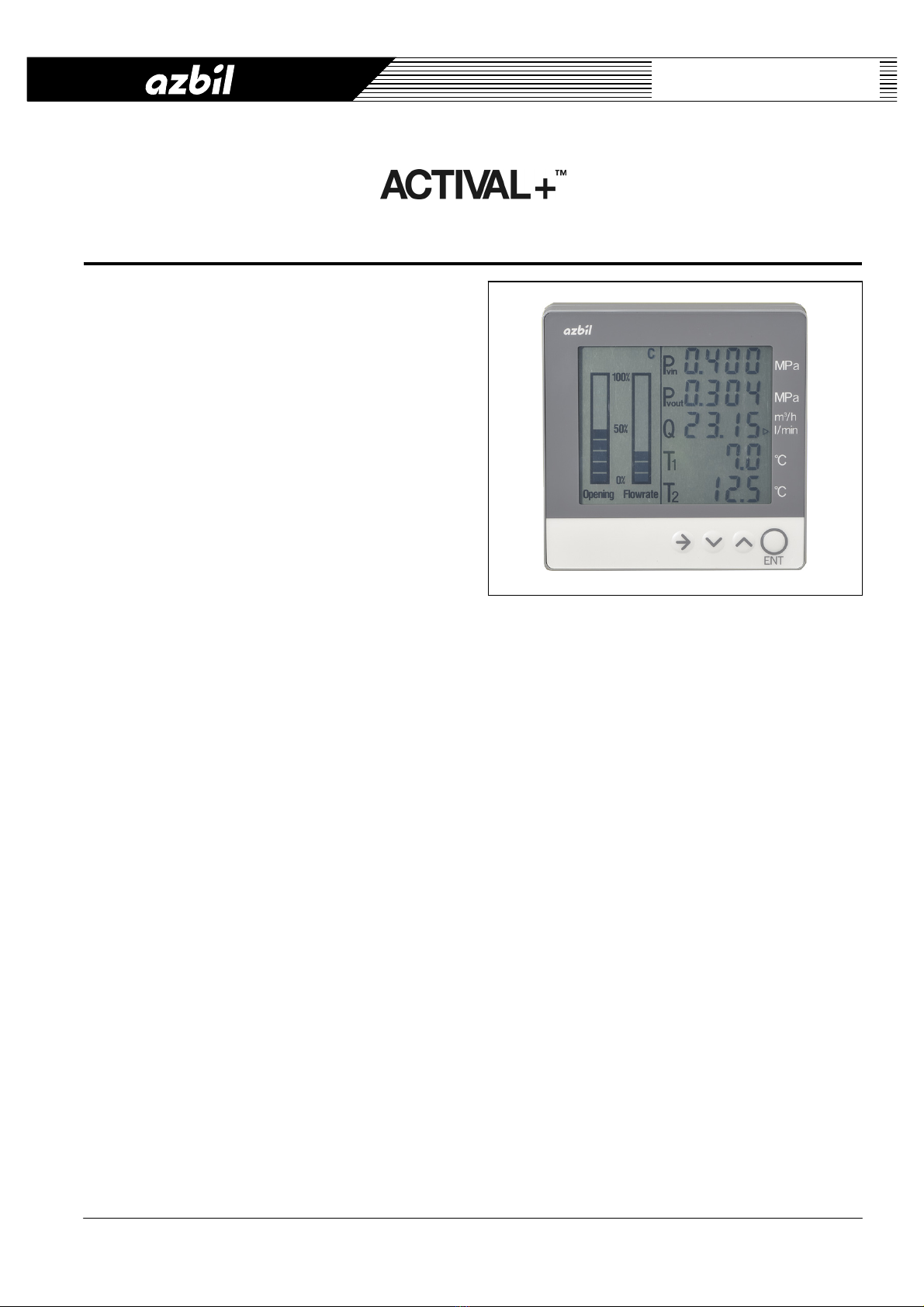
Display*2 Device Liquid Crystal Display (LCD)
Items to display Pvin Valve inlet pressure (MPa or kPa)
Pvout Valve outlet pressure (MPa or kPa)
Q Actual flow (m3/h or l/min)
T1 Coil inlet temperature (C)
T2 Coil outlet temperature (C)
HC Heat/Cool
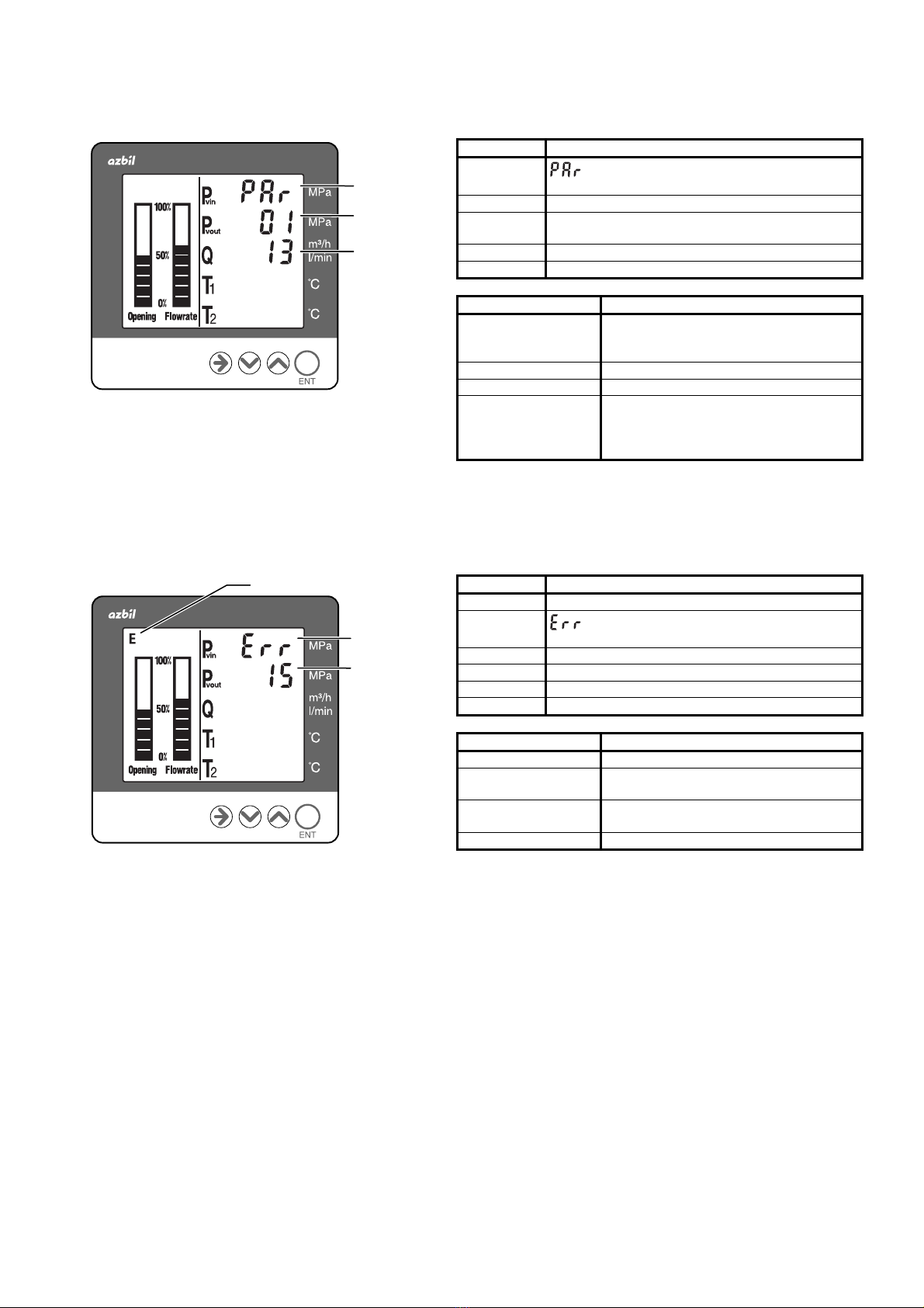
E Error
Opening Actual valve position (% in bar graph)
Flowrate Actual flow rate (% in bar graph)
Communication Transmission system AP-bus (RS-485 communication)
Transmission speed 4800 bps
Transmission distance Max. 50 m
Number of Display Panel
connectable One per single Model FVY513_J/FVY514_J/FVY515_J
Materials Case Modified polyphenylene ether (PPE)
Base plate Modified polyphenylene ether (PPE)
Face plate Polyester (PET)
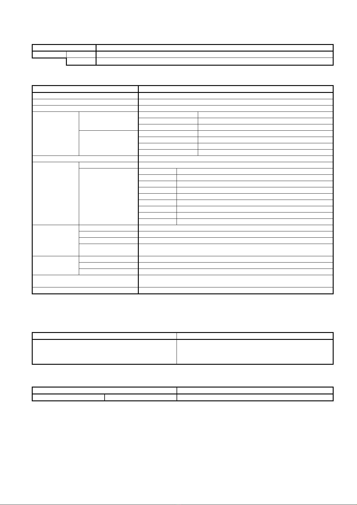
Accessory - Two tapping screws (M4) for mounting
- Two 'kPa' unit stickers
Weight 150 g
Notes:
*1 LCD service life may shorten if Display Panel is used in an environment with high temperature and humidity.
*2 For display accuracy, refer to specification data of Model FVY513_J/FVY514_J/FVY515_J.
Recommended Wire Specifications
Cable type Wiring length
Flexible cable (Cabtire cable), 0.3 mm2 × 4-core,
dia. 4.5 mm to dia. 6.0 mm /
JIS*3 VCTF cable , 0.3 mm2 × 4-core , dia. 4.5 mm to dia. 6.0 mm.
(Cable is not supplied with Display Panel.)
50 m
*3 JIS: Japanese Industrial Standards
Option
Item Note
Waterproof box Part No. 83170324-001 Required when Display Panel is installed outdoors.