Vmatte Vmatte-HD HDL4.2 User manual

Vmatte-HD Chroma Keyer
Operation Manual
Version : HDL4.2

Table of Contents
1. Quick Start
Setup Hardware …………………………………………………………………
Install Software …………………………………………………………………
Choose Working Environment …………………………………………………
Select Inputs and Outputs ………………………………………………………
Configure Video Process ………………………………………………………
Store and Recall …………………………………………………………………
2. Hardware Overview
2.1 Front Panel …………………………………………………………………
2.2 Rear Panel …………………………………………………………………
2.3 Block Diagram …………………………………………………………………
3. MBS Remote installation
3.1 System Requirements ………………………………………………………
3.2 Software Installation ………………………………………………………
4. Software Operations
4.1 About MBS Remote ………………………………………………………
4.2 Config ……………………………………………………………………….
4.3 Store & Recall …………………………………………………………………..
5. Product Features
5.1 Multi CameraUnit Support ………………………………………………….
5.2 Multi Channel Support ………………………………………………………..
6. Video Processing
6.1 Input ……………………………………………………………………………..
6.2 PreAmp ………………………………………………………………………..
6.3 Chromakey
6.3.1 Matte Generation ………………………………………………………..
6.3.2 Spill Suppression ………………………………………………………..
6.3.3 Edge Fix …………………………………………………………………..
6.3.4 Dark, Bright and Shadow ……………………………………………..
6.4 External Matte
6.4.1 External Matte ………………………………………………………..
6.4.2 Composite Control ………………………………………………………..
6.4.3 Composite with Cutoff Key Mode …………………………………..
6.4.4 Composite with Area Key Mode ………………………………………..
6.4.5 Composite with Layer Key Mode………………………………………..
6.4.6 Composite with Multiple Key Mode …………………………………..
6.5 PostAmp ………………………………………………………………………..
6.6 BG Defocus …………………………………………………………………..
6.7 Window ………………………………………………………………………..
6.8 Fade ……………………………………………………………………………..
6.9 Output ………………………………………………………………………..
A1. Vmatte-HD Workflow ……………………………………………………………..
A1.1 Chromakey Workflow - Blue Screen ………………………………………..
A1.2 Chromakey Workflow - Green Screen …………………………………..
Vmatte Corp. 2014/6
1
1
2
2
3
4
5
6
7
8
9
10
11
12
13
14
15
17
18
23
27
29
32
34
36
38
40
42
45
46
47
50
52
53
54
55
Quick Start
This Quick Start guide is for the Vmatte HD chromakey hardware with firmware versions 4.2 and above. The operating software is
MBS Remote 4.
Contents
Setup Hardware
Install Software
Choose Working Environment
Select Inputs and Outputs
Configure Video Process
Store and Recall
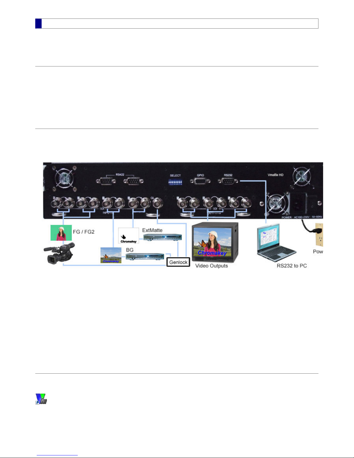
Setup Hardware
Connections
All connectors are located on the rear panel of the Vmatte HD hardware. The following picture shows an example connection with four
inputs.
Plug the power cable into a 110~230V, 50~60Hz, AC power outlet1. Connect the RS232 cable to a PC COM port for software control (both ends are DB9 female)2. Connect SDI video sources to INPUTS connectors. At least two inputs, a foreground and a background, are required to create a
chromakey result.
3.
Connect video monitors or recording devices to output SDI or YUV connectors. OutputA is for preview only and OutputB is for
recording or broadcasting.
4.
(Optional) Connect a genlock input to the GL connector. The genlock input can be a SD black burst (bi-level) or HD tri-level genlock
source.
5.
Power On
The power button is located at the bottom-right corner of the rear panel. The POWER LED on the front panel lights up after the power-on
process ends. Refer to the Front Panel section for details.
Install Software
In the MBS_Remote 4 installation package, double-click the file SETUP.Exe and follow the instructions. A desktop shortcut icon appears
after installation.
Run MBS_Remote
MBS Remote User Manual.pdf 1 2014/6/13 PM 02:23:37
1

After software installation, double-click the MBS_Remote 4 shortcut icon on the desktop. When the MBS Remote runs for the first time, it
synchronizes from the hardware through port COM1 by default. To assign another port, click the COM port button located at the
bottom-right corner of the MBS Remote window and select the appropriate port. The COM port selection is stored in memory, and
therefore not necessary to be reassigned next time.
Choose Working Environment
Menu bar selections
The following settings are optional and should be changed as needed.
Language – Select from English, Simplified Chinese, and Traditional Chinese
Option – Enable Multi CameraUnit Support and Multi Channel Support
Recall – Recall one of the user settings and select a synchronization method (see Store & Recall)
Help – View this help document and open the About dialog, which contains software, firmware, and hardware version information.
Feature Tabs
Feature tabs are organized by the order of video processes. This Quick Start guide described the minimum set of controls required to
produce a chromakey result. These controls are located in Input, Chromakey, and Config tabs. The new ExtMatte/Composite tab
is only available for firmware version 4.2 and above.
The MBS Remote automatically detects input video type and configures corresponding hardware settings. It also provides a setting for
output video type, which is necessary when no input video source is present, such as temporarily freezing an input video while
unplugging the source. To set the output video type, click on the Config feature tab and set the Video Standard as described below.
Video Standard and Operation Options
Video output standard is automatically detected from the input sources in the priority order of FG (foreground), BG (background), and
ExtMatte (external matte). If none of the input sources is present, video output standard is assigned according to the Default System
setting. The Component Output selection is for component video. If the output is composite instead of component, flip on the SELECT 3
switch on the rear panel of the Vmatte HD Hardware. See the Config section for details.
Select Input and Output
Input
Click on the Input feature tab. Choose input slot and type according to FG, BG, and ExtMatte video inputs. Video types are
MBS Remote User Manual.pdf 2 2014/6/13 PM 02:23:38
2

automatically detected and displayed in the Status column for verification. For more information on freeze, genlock, and frame delay
settings, see the Input section.
Output
There are two rows of output buttons. The first row (OutputA) is a preview output and the second row (OutputB) is for broadcasting or
recording. OutputA and OutputB can be selected independently while OutputC is identical to either OutputA or OutputB. The
selections for OutputA and OutputB are:
Output Meaning
FG / FG2 Foreground input / second foreground (refer to the Input FG2 section)
BG Background input
ExtMatte External matte input
Matte Chromakey mask
PFG Process foreground for evaluating chromakey effect
Comp Final composite result
Configure Video Process
Video is processed in the following order:
– Adjust color, brightness and white balance for input video sources (PreAmp)
– Generate matte, suppress spill, and enhance foreground (ChromaKey)
– Adjust color, brightness and white balance for processed foreground (PostAmp)
– Clean up or preserve part of the foreground in the final composite (Window)
– Switch one video scene to another (Fade)
Open the corresponding feature tab to configure a particular process if needed. The default settings in the feature tabs are suitable for
most cases and do not need to be changed during initial setup. However, it is necessary to verify that chromakey settings are applicable
to the studio environment. To do so, open the ChromaKey feature tab and perform the following steps:
Choose a Back Color
The Back Color represents a sample color of a blue or green screen. Colors that are similar to the Back Color in the foreground are
removed and replaced with the background in the composite output. There are three methods to choose the Back Color in the Matte
Generation section:
Enter R, G, B values in the three text boxes as shown below
Click on the square color button and choose a color when a dialog appears
Click on the Pick button to choose a color when a dialog appears (more on Pick from the Foreground)
MBS Remote User Manual.pdf 3 2014/6/13 PM 02:23:38
3

Adjust Open Angles
The two parameters, Open Angle -/+, determine the colors that need to be removed along with the Back Color. Usually there is no
need to change their default values unless a foreground color is keyed out in the final composite. To recover the missing foreground
color, click on the color directly as shown below.
Remove Noise
To determine if there is any noise to be removed, choose Matte output while monitoring video result. If blue or green screen area is not
completely black in the matte output, increase the Noise Removal value; otherwise no change is necessary.
Suppress Spill
The three default spill suppression settings (low, mid, high) are suitable for most cases. The default Spill Low preserves foreground
colors that are close to the Back Color. To recover the foreground colors that are severely altered by lighting or reflection, use Spill
High. Other techniques for fine-tuning spilled colors are described in the Spill Suppression section.
Other Chromakey Parameters
Refer to Edge Fix, Dark and Bright Enhancements, and External Matte for details.
Store and Recall
To save the current parameter settings for later use, perform the following:
Open the Store/Recall feature tab1. Check one of the square boxes2. Rename the description next to the square box3. Click Save Changes4.
See Store & Recall for details.
MBS Remote User Manual.pdf 4 2014/6/13 PM 02:23:38
4
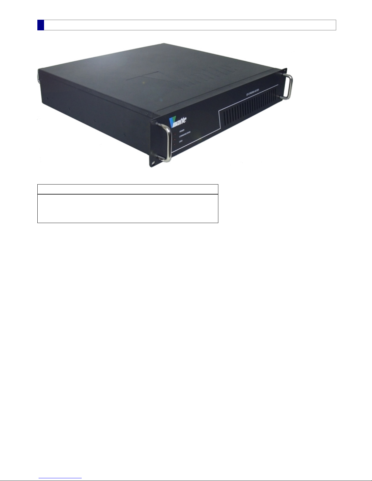
Front Panel
The front panel displays three status LEDs:
LED Action
POWER Indicates power on/off status
COMMUNICATION Blinks during PC remote control and recall actions
GPI Lights up for 1 second when GPI action takes place
All three LEDs light up during the power on process, which lasts about 10 seconds. At the end of the power-on process, the video
output displays 75% color bars for 2 seconds then shows a default output or a previously selected output.
MBS Remote User Manual.pdf 5 2014/6/13 PM 02:23:38
5
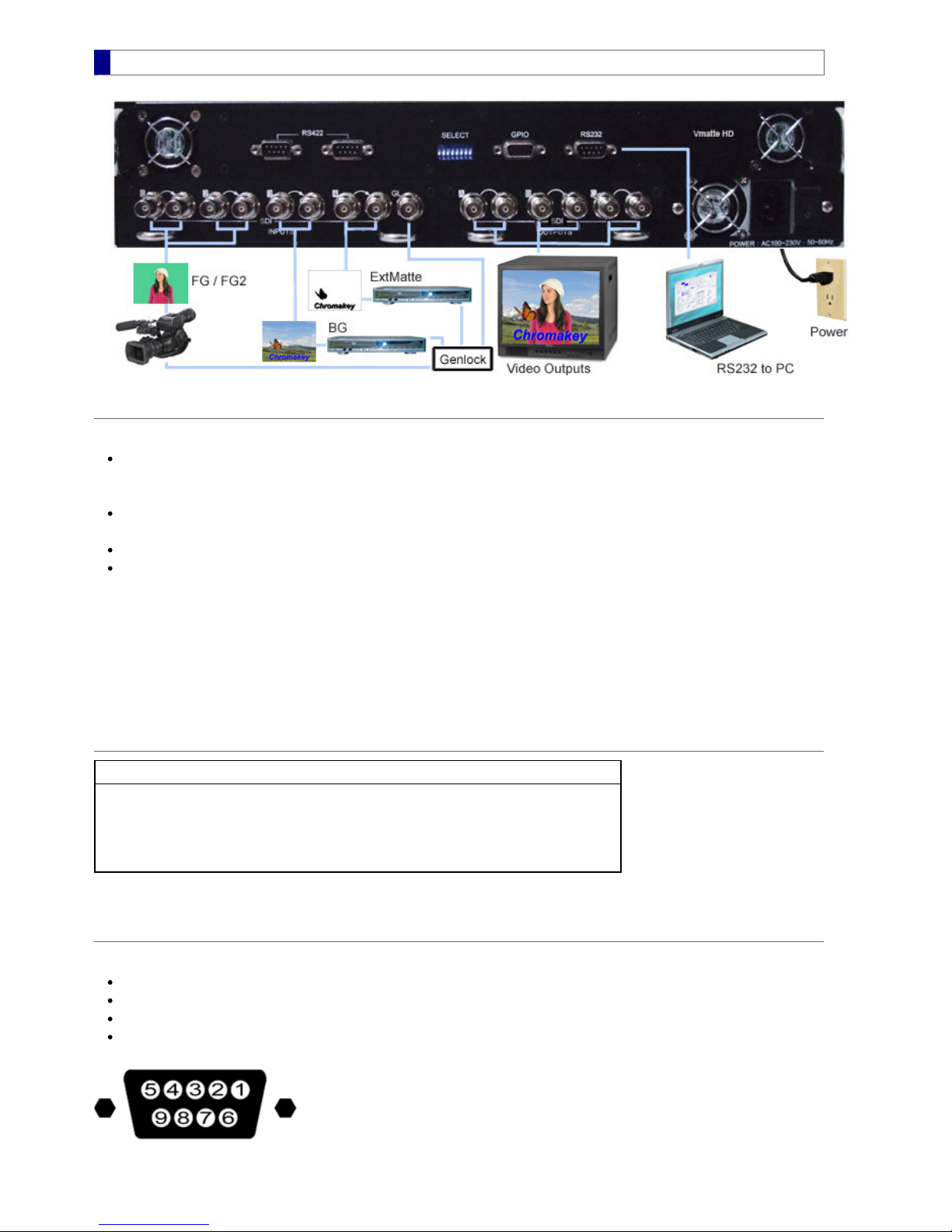
Rear Panel
Connections
Example connections as shown in the above picture, from right to left:
Power plug and RS232
Power – 110~230V AC, 50~60Hz
RS232 – to PC COM port for remote control (both ends are DB9 female)**
Video outputs A, B, and C (OutputA: SDI x 2, OuputB: SDI x 1, OutputC: YUV or CV/S-Video)
These may be connected to a SDI monitor, a YUV monitor, and/or a video recorder
Genlock input (GL)
Video inputs 1~4 (SDI x 4, including loop through outputs)
The followings are shown in the picture. Other types of inputs can be connected as well.
- two SDI video cameras to INPUT1 and INPUT2 as switchable foregrounds
- a DVD player to INPUT3 as a background
- a DVD player to INPUT4 as an external matte
**A USB-RS232 adapter that can be used in Mircosoft Windows 2000/XP/Vista/7, for either 32- or 64-bit OS, is shipped along with the
Vmatte chromakey hardware.
SELECT switches
SELECT OFF ON
1 RS232 RS422
3 Component output YUV / RGB Composite output CV / S-Video†
7 Fast genlock (2~6 seconds,
a little unstable) Slow genlock (4~8 seconds,
more stable, for firmware 2.507~)
†Requires conversion of SY / SC to S-Video through a BNC cable
GPIO
The GPIO pin definitions are:
Pin 1~3: GPI 1~3
Pin 4: GPO1 (connect to Tally 1, max. 35VDC)
Pin 5: GPO2 (connect to Tally 2, max. 35VDC)
Pin 6~9: GND
For chromakey hardware labelled with Tally 1,2 support and equipped with a firmware version 2.508~2.999 or 3.012~4.999, GPO1 and
GPO2 support multi-camera tally lights with the following switch table:
MBS Remote User Manual.pdf 6 2014/6/13 PM 02:23:38
6
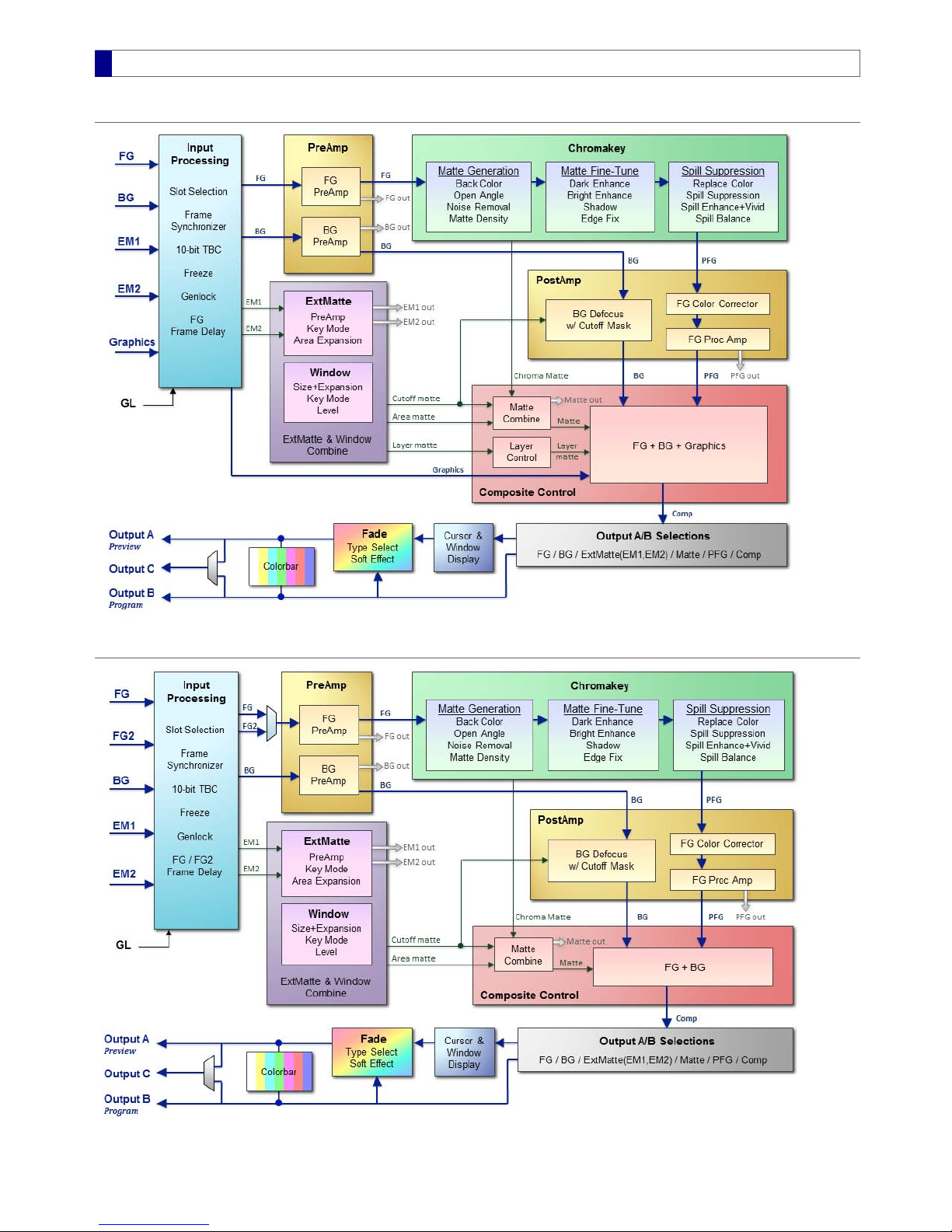
Block Diagram
Chromakey + Dual ExtMatte + Graphics Layer
Chromakey + Dual ExtMatte + Dual FG
MBS Remote User Manual.pdf 7 2014/6/13 PM 02:23:38
7

System Requirements
The followings are the minimum system requirements:
Operating System
Windows 2000, Windows XP / Vista / 7 / 8
Hardware
RS232 Serial Port
600MHz Pentium class processor
64MB RAM
5MB free drive space
1024 x 768 16-bit color or higher adapter
MBS Remote User Manual.pdf 8 2014/6/13 PM 02:23:38
8

Software Installation
Select and run Setup.Exe from the installation package
A new installation replaces an older version of the same software automatically. It is not necessary to uninstall the older version
before the upgrade. User settings are preserved during software installation as long as the file MBS_Remote.ini is not removed from
the MBS Remote folder.
MBS Remote, MBS Remote 2, MBS Remote 3, and MBS Remote 4 are considered different software because they are installed as
separate Program File entries in the computer. Therefore, they can coexist and be uninstalled individually.
MBS Remote User Manual.pdf 9 2014/6/13 PM 02:23:38
9

About MBS Remote
Hardware model, channel, and hardware/firmware/software version information can be found in the About window. To view the
About window, click Menu > Help > About.
MBS Remote User Manual.pdf 10 2014/6/13 PM 02:23:38
10

Config
Output video type and function mode are located in the Config feature tab.
Video Standard
Default System
Video output standard is automatically detected from input sources in the priority order of FG, BG, and ExtMatte. If none of the input
sources is present, video output standard is assigned according to the Default System setting. The Vmatte HD supports the
following Default System selections – NTSC, PAL, 720p60, 720p59, 720p50, 1080i60, 1080i59, 1080i50, and 1080PsF24.
Component / Composite Output
The factory default video type is Component and its color channels can be either YUV or RGB. If a Composite output is needed,
flip the SELECT switch #3 on the rear panel. The switch setting is:
OFF – Component output YUV or RGB, depending on the selection of Component Output.
ON – Composite output CV / S-Video. A dual BNC (SY/SC) to S-Video cable is required for the S-Video output.
Operation Options
The standard operation of Vmatte HD is FG ChromaKey + ExtMatte, which applies a professional chromakey to a foreground video
and combines the foreground with a background and an external matte. The Vmatte HD can also take two simultaneous foreground
inputs and perform real-time switch between these two foregrounds when either the background or the external matte is not used.
Advance Operations
Besides the standard operation, the Vmatte HD offers two advanced modes. To show the options for these modes, perform the
following steps:
On the rear panel of the Vmatte HD, locate the SELECT switch #71. Flip the switch #7 to the ON position2. Select one of the Operation Options as illustrated below3.
The operation option Chromakey + Dual ExtMatte + Graphics Layer is a new feature of the Vmatte HD hardware. With this
option, an additional graphics layer input can be inserted on top or underneath the chromakey-processed foreground. Refer to
Graphics Layer section for more information and examples.
The operation option Chromakey + Dual ExtMatte + Dual FG is similar to the standard mode FG ChromaKey + ExtMatte plus two
additional features:
An extra input that can be used as the second external matte or the second foreground
Key mode selections and combinations for the two external mattes
Upon selecting the Operation Options, the user interface for Input, PreAmp, ExtMatte/Composite, and Window feature tabs
are automatically updated to provide appropriate control settings. Any unused feature can be turned off in these tabs.
MBS Remote User Manual.pdf 11 2014/6/13 PM 02:23:38
11

Store and Recall
Click on the Store/Recall feature tab to view settings:
The MBS Remote software can store up to ten parameter settings for later recalls. These settings are saved in the MBS_Remote.ini file
under the MBS Remote installation folder (usually in C:\Program Files\MBS_Remote). To use the same settings on another PC, simply
copy the MBS_Remote.ini file to the installation folder of the target PC.
Store Parameters
Save Changes
Use the following steps to store current parameters:
Select one or more square boxes next to setting number 1~10. The top-most box is used to check/uncheck all.1. Enter names for the checked setting. The default text is Setting1~Setting10.2. Press Save Changes button.3.
Discard Changes
Unsaved changes are discarded. The MBS Remote software reloads the settings saved in MBS_Remote.ini.
Recall Parameters
Use either one of the following methods to recall pre-stored parameters
Click on one of the recall button at the end of Setting1 ~ Setting10
Click on Menu > Recall menu and select an item
Upon recalling, parameters of the selected settings are loaded into software interface and passed on to all channels (meaning hardware
units, see Multi-Channel section for details). Output video is updated to reflect newly loaded settings after the completion of the recall
process. See the Status section on how to monitor the recall process.
Startup Settings
To choose the settings for the next software startup, click on one of the 12 round radio buttons:
Setting 1~10 – load the selected setting to all channels
Sync From Machine – obtain settings for the current channel, then load to software interface and to all other channels
Load Factory Default – load default settings to all channels
MBS Remote User Manual.pdf 12 2014/6/13 PM 02:23:38
12

Multi CameraUnit Support
Multiple Parameter Sets
The Vmatte HD hardware can store up to four sets of chromakey parameters for each of the four cameras. Each camera may have
different environment settings and lighting conditions that require different chromakey parameters. Switching between cameras or
parameter sets is performed during active video's vertical blanking and does not affect the viewable video result.
The MBS Remote software and its API synchronize the camera switch with a background change so that the composite result can
make a transition from one scene to another smoothly. This feature allows a single Vmatte chromakey hardware to perform tasks
equivalent to four pieces of other chromakey hardware.
During the hardware power-on process, the parameters of a previously selected camera unit are loaded.
Enable Multi-Camera Units
The Multi CameraUnits Support is turned off by default. Click Menu > Option > Enable Multi CameraUnit Support to enable this
feature.
Once enabled, Switch to Camera 1~4 will appear in the Option menu. In addition to the menu, a CameraUnit Switch box with
four buttons appears on the upper-right corner of MBS Remote window.
Multi-Camera Switch
Choose one of the following methods to switch between cameras
Select from the Option menu
Click one of the button 1~4 in the CameraUnit Switch box
Press one of the hotkeys Ctrl-F1~Ctrl-F4
The following functional tabs contain multiple parameter sets. However, the user interface only displays parameter values for the
currently selected camera unit. In order to view settings for another camera unit, simply make that camera unit active.
PreAmp, except external matte polarity
Chromakey, except matte polarity and external matte on/off
PostAmp
Window
Store / Recall
When multiple camera units are active, all four parameter sets need to be read or write. Therefore, the store/recall operation time
for four cameras is longer than that for a single camera.
Uncheck the menu item Enable Multi CameraUnit Support returns all operations to the single camera unit mode. Under the single
camera unit mode, parameter set for Camera 1 is used .
MBS Remote User Manual.pdf 13 2014/6/13 PM 02:23:39
13

Multi Channel Support
What is Multi Channel Support
The Multi Channel Support allows two or more units of chromakey hardware to be controlled by the same MBS Remote software.
Although four sets of parameters can be stored in a chromakey hardware, only one set is controlled at a time. Therefore, there are
situations when multiple units of chromakey hardware are required. In these situations, the MBS Remote software can connect to
multiple chromakey hardware, maintain their parameter synchronizations, and monitor their corresponding video results.
Enable Multi-Channel
Click Menu > Option > Enable Multi Channel Support to turn on the multi-channel feature:
After a port is opened, set number of channels, corresponding COM-port, and sync operation:
Once enabled, channel buttons show up on the lower-right corner of the MBS Remote window. Currently selected channel is
displayed as a blue button with its corresponding COM-port displayed on the rightmost button.
Possible COM-port status
green – normal
sky-blue – device timeout
red – COM-port not selected
yellow – COM-port used by another software
Change Settings
To change the COM-port for any channel, do one of the following:
Select an item in the Option menu
Click the COM-port button, then click Multi Channel Setup to select more than one channels
MBS Remote User Manual.pdf 14 2014/6/13 PM 02:23:39
14
Input
The Input feature tab contains input source, genlock, and frame delay settings
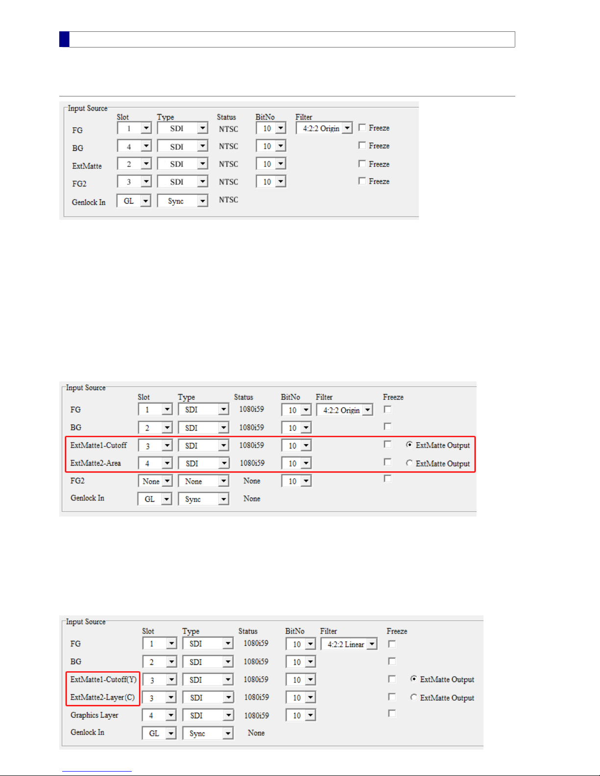
Input Source
It is necessary to select correct input Slot for any video source used in the production. If an input is unused, its slot should be set to
None. Video types are automatically detected and displayed in the Status column.
Slot with no Input
If there is no valid video signal coming from an input connector and the corresponding slot selection is not None, the Vmatte hardware
will send a constant color (which is set to the Fade Color) to that input channel.
Dual External Matte Inputs
* This feature requires the advanced Operation Options
The Vmatte HD can accept two external matte sources. These external mattes may be operated in different key modes to create various
composition effects. The status of the current key modes are displayed next to the ExtMatte1 and the ExtMatte2 texts. In the
following picture, the ExtMatte1 is in the Cutoff key mode and the ExtMatte2 is in the Area key mode. Refer to External Matte for
key mode settings and usages.
Multiplexed Inputs
* This feature requires the advanced Operation Options
Since an external matte is monochromatic and only occupies the luma channel, it is possible to multiplex two external mattes into one
input slot. This requires proper preparations for both input sources, especially the ExtMatte2 which is transmitted through the chroma
channel in the multiplexed mode. Once the input sources are ready, simply select the same source slot for both external mattes. MBS
Remote will reflect the multiplexed status by adding a suffix "(Y)" or "(C)" to the ExtMatte1 and ExtMatte2 texts as shown in the red
box of the following picture.
MBS Remote User Manual.pdf 15 2014/6/13 PM 02:23:39
15
Checking Input Video
To verify whether an input connection is correct, press the corresponding button on Output A, then check video monitor result.
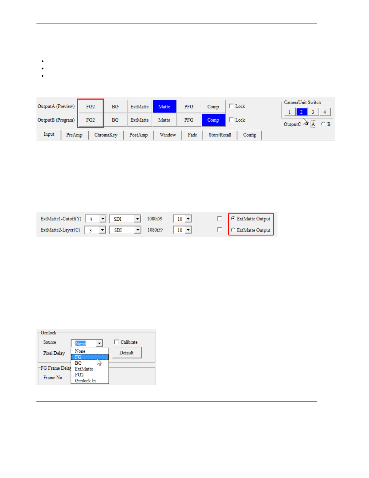
Viewing FG2
In order to see the FG2 output, the current camera unit needs to be Camera 2. To select and set up this camera, do the followings:
Check Menu > Option > Enable Multi CameraUnit Support
Check Switch to Camera 2
Make sure FG2 input is valid by checking its Status column
After performing these steps, the FG2 buttons appear in the output selection area as shown in the red rectangle below. Click the FG2
button on Output A and check video monitor result.
NOTE:The FG2 option is not available when configuration is set to Chromakey + Dual ExtMatte + Graphics Layer.
Viewing External Matte
* This feature requires the advanced Operation Options
The external matte input is a gray-scale video that can be used to control keying area or achieving special composition effects. If a color
input video is selected as the external matte, only its luma component is processed. Refer to External Matte for detailed descriptions on
settings and applications.
In the Input Source panel, the two external matte inputs can be selected independently. In order to view either of the external matte on
a video monitor, select an ExtMatte Output at the end of the rows and press OutputA > ExtMatte on top of the application.
NOTE: Any unused external matte input slot should be set to None.
Freeze
To repeat a frame (as if the output is frozen), check the corresponding Freeze square box. All freeze controls are independent fromn
each other.
Genlock
Video output may be genlocked to any of the four input videos, or to a dedicate genlock input (Genlock In). The genlock input can be a
SD black burst (bi-level) or HD tri-level genlock source connecting through the GL connector located on the hardware rear panel. On
the MBS Remote, the Genlock In has slot setting GL and input type Sync. The extra delay for Genlock In is adjustable from -1024 to
1023.
FG Frame Delay
This is used to delay foreground frames (for either FG or FG2) so that a foreground can be synchronized with a computer generated
background when necessary. The maximum frame delay amount is 15 for the Vmatte HD hardware.
MBS Remote User Manual.pdf 16 2014/6/13 PM 02:23:39
16
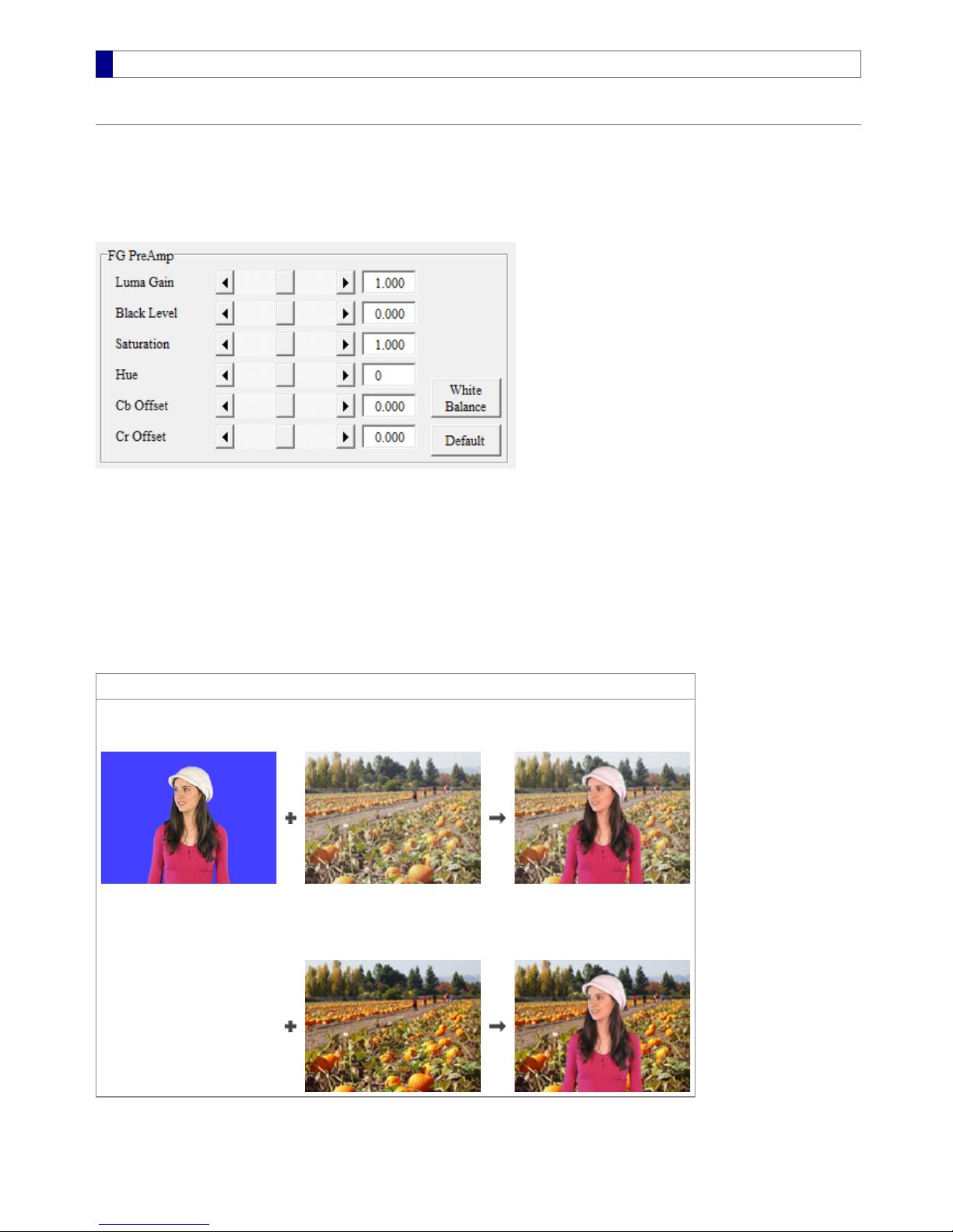
PreAmp
FG and BG PreAmp
The FG and BG PreAmp panels contain various color, brightness and white balance adjustments for the foreground and the
background. These adjustments may be used to compensate for non-ideal inputs or to achieve speical tint/lighting effects. The FG
PreAmp adjustments are processed before chromakey and will affect the chromakey. Therefore, once a satisfactory chromakey
result is achieved, PostAmp should be used on the processed foreground (PFG) or the composite result (Comp) instead of FG
PreAmp. On the other hand, BG PreAmp can be used independently of the chromakey.
Default
Clicking the Default button changes all adjustment controls to their default values, which are set to bypass the foreground and the
background without any PreAmp processing.
White Balance
A cursor-picking dialog appears when the White Balance button is pressed. Simply select an appropriate pixel as the reference
color.
Example. Matching anoverlyexposed background to the foreground
Foreground Composite
Foreground
with vivid colors Background with
washed-out colors Foreground and background
do not match
Background with
decreased Black Level and
increased Saturation Better composite result
MBS Remote User Manual.pdf 17 2014/6/13 PM 02:23:39
17
Matte Generation
The Matte Generation panel is located in the ChromaKey feature tab and consists of the following controls:
Back Color – choose a blue or green screen color sample
Opened Angle – specify the color range for the blue or green screen that needs to be removed from the composite result
Noise Removal – remove noises that come from imperfect blue or green screen
Matte Density – preserve dark and bright objects
Transparency – uniformly adjust chroma matte so that a solid foreground may become transparent
Polarity – invert the final matte output without affecting the matte used in the compositing process
External Matte – remove unwanted foreground objects or create a third layer (see External Matte section)
Back Color
The Back Color represents a sample color of a blue or green screen. Colors that are similar to the Back Color in the foreground
input source are removed and replaced with the background in the composite output. Use one of the following methods to choose a
Back Color:
Enter R, G, B values in the three text boxes
Click on the square color button and choose a color when a dialog appears
Click on the Pick button to choose a color from the foreground when a dialog appears. This usually produces the best results
for a nonstandard Back Color.
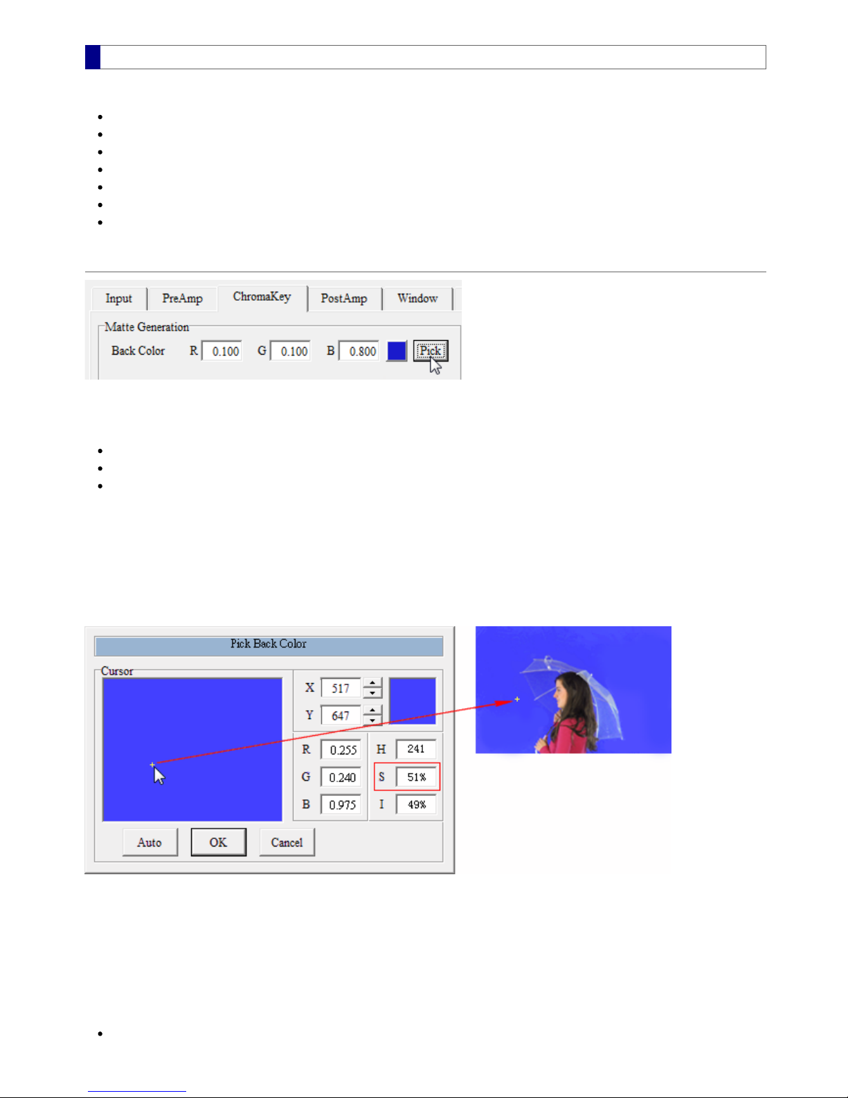
Pick from the Foreground
After clicking the Pick button, a dialog Pick Back Color appears. At the same time, OutputA switches to foreground automatically
so that the picking location and its associated color can be seen on an output monitor. To change the cursor location, move the
cursor in the large rectangular area, or enter the cursor location as integer values into X(horizontal) and Y(vertical) text boxes. The
color of the large rectangle reflects the foreground color detected at the cursor center.
How to Choose a Good Back Color
If the blue or green screen has washed-out areas, avoid picking in these areas. Instead, choose the most saturated colors as the
Back Color. The most saturated color has the largest S(saturation) value, which can be found inside the red rectangle in the
above picture.
Close Dialog
After choosing a Back Color, click OK or Auto to close the dialog.
OK – set currently selected color as the Back Color without changing other settings
MBS Remote User Manual.pdf 18 2014/6/13 PM 02:23:39
18
Table of contents


