Azden FMX-42 User manual

4-CHANNEL FIELD MIXER
Azden Corporation
147 New Hyde Park Road
P.O.Box10
FranklinSquare,NY11010
vox516.328.7500•fax516.328.7506
FMX-42
INSTRUCTIONS
Rev. 4

Mic
(
-
30 position) Standard -30 dBu (electronicallybalanced)
Maximum +4 dBu
Mic (-50 position) Standard -50 dBu (electronicallybalanced)
Maximum -11 dBu
Impedance
Line 20 k ohm
Mic 2 k ohm
High Pass Filter (HPF) 100 Hz –6 dB/oct
OUTPUT
Balanced Output XLR 3-pin x 2 (OutputL and R)
Unbalanced Output 3.5 mm (1/8") Stereomini-jack
Monitor Output 6.5 mm (1/4")Stereo jack
Level
Balanced Output Standard +4 dBu (> 10 k ohm load)
-2 dBu (600 ohm load)
Maximum +20 dBu (>10k ohm load)
+13 dBu (600ohm load)
Unbalanced Output Standard -36 dBu (>10 kohm load)
Maximum -20 dBu (> 10 kohm load)
ToneGenerator 1 kHz @ +4 dBu
Monitor Output Maximum +1 dBu (32 ohm load)
16-100 ohm load recommended
Output Impedance Balanced 600 ohm
Unbalanced 120 ohm
Meters
Standard Output Level 0 VU (+4 dBu)
GENERAL
Frequency Response
Balanced or
Unbalanced Output 20 Hz - 30 kHz (+0 / -1.5 dB)
Monitor Output 30 Hz - 30 kHz (+0 / -2 dB)
Signal-To-Noise
Balanced Output -120 dBu (A weighted, InputEquivalent Level)
T.H.D.
Balanced Output <0.005% @ 1 kHz (@ LINE position +19 dBu output)
PhantomPower Voltage 48V (± 4V)
Power
Battery Requirement 6 Alkaline “AA”
Battery Runtime Approx. 10 hours (Meter Illum. OFF/Phantom Power OFF)
External Power 12VDC @200 mA
Current Drain 155 mA (Meter Illum. OFF/Phantom Power OFF - @ 9V)
195 mA (Meter Illum. OFF/Phantom Power ON w/2-SGM-1000 - @ 9V)
Dimensions 56H x220W x150.5D mm (without protrusions)
1.968H x8.6614W x 5.9055D inches (without protrusions)
Weight 1400g (withoutbatteries)
49.3835 oz (without batteries)
INPUT
Balanced Input XLR 3-pin x 4 (CH1, 2,3 and 4)
Level
Line Input Standard +4 dBu (electronically balanced)
Maximum > +26 dBu (=4 dBuposition)
FMX-42 SPECIFICATIONS
3
4
1
2
65
8
7
12
13
14
10
11
9
15
9
13
17
18
19
20
21
16
22
23
2425 2627

INTRODUCTION:
ThankyouforpurchasingAzden’sFMX-424-channelfieldmixer.TheFMX-42has
manyuniquefeatures,makingitveryimportanttoreadandunderstandthismanual
completelybeforeuse.Designedtoworkwithmostmicrophonesthathavealow-
impedanceXLRoutputorline-leveldevices,theFMX-42’soutputcanbeconnected
tovirtuallyanyvideocameraoraudiorecorder,whichhasXLRormini-connector
mic/lineinputs.
POWERING THEFMX-42
Battery Power:
Make sure the mixer is turned “OFF” (2). Remove the battery cover (1) by
pressingtheclipinandthenliftingupandremovingthecoverfromtheunit.Install6
fresh“AA”ALKALINE batteriesfollowingthepolaritydiagraminsidethebattery
compartment.Donotforcethebatteries.Whenall6batteriesareinstalled,replace
the battery cover and move the power switch (2) to the “BATT” position. The
“POWER”LED(4)willturnGREEN.Whenthebatteryvoltagelevelbecomestoo
low for proper operation the “POWER” LED will turn RED. When this happens
replacethebatterieswithfresh,new“AA”ALKALINEbatteries.Whennotinuse,
turnthemixer“POWER”switch(2)to“OFF”toconservebatterylife.
ExternalPower:
TheFMX-42can be poweredfromanexternalpower supply.Afterattaching the
powersupplytoanactive110VACsourceandtothe“EXTDCIN”jack(3) onthe
FMX-42,movethepowerswitch(2)tothe“EXT”position.The“POWER”LED(4)
will turn green. When not in use, turn the mixer “POWER” switch to “OFF” and
disconnectthepowersupplyfromthemixer.
Wearing the FMX-42:
TheFMX-42issuppliedwithaballisticnyloncase.Placethemixerinthecaseand
adjust the neck strap to achieve the most comfortable position for you. A back
harness(notsupplied)canbesecuredtothemetalringsonthecaseforadditional
supportandcomfort.
INPUTS and SETTINGS
“INPUT” Channels: “CH 1”, “CH 2”,“CH 3” and “CH 4”
Connecttheoutputofamicrophone,wirelessreceiverorline-levelaudiocompo-
nent to “INPUT CH 1” (5) and/or “CH 2” (5) and/or “CH 3” (5) and/or“CH 4” (5).
Theinputsacceptastandard3-pinmaleXLRconnectorequippedcable.Pushthe
connector into the input jack until it locks. To remove the connector, press the
“PUSH”tab(6)andpulltheconnectorout.
Illustration numbers:
Shown in the instructions within ( ), these numbers refer to the illustrations on the inside cover.
Note:TheFMX-42isnotsuppliedwithanexternalpowersupply.Anoptionalpowersupply,
partnumberBC-26U,isavailablefromAzden’swebsite:www.azdencorp.com.
14
OUTPUTS and SETTINGS
Monitor “LEVEL” and “MONITOR” Output Jack:
The“MONITOR”“LEVEL”(22)adjuststhevolumeofheadphonesconnectedtothe
“MONITOR”outputjack(23).Zeroisthelowest(quietest)setting,10isthehighest
(loudest).
Monitor “SELECT”:
Normally,themonitor“SELECT”switch(24)issettoposition“L/R”.Inthisposition
youwillmonitorthesoundofallconnectedmicrophonesusingstereoheadphones.
Ifyouonlywanttohearthe“L”output,usestereoheadphonesandsettheswitchto
position“L”.Or,ifyouonlywanttohearthe“R”output,usestereoheadphonesand
settheswitchtoposition“R”.Theuseofmonoheadphonesisnotrecommended.
“OUTPUT” “L” and “R”:
Connectacablefrom“OUTPUT”“L”(14)and/or“OUTPUT”“R”(15)tothemicro-
phoneorlineinputofyourvideocameraoraudiorecorder.Theseoutputsaccept
astandard3-pinfemaleXLRconnectorequippedcable.Pushthecableconnector
intotheoutputjackuntilitlocks.Toremovetheconnectorpressthereleasetabon
theconnectorandpulltheconnectorout.
“OUTPUT” “LEVEL” Settings:
Select the “OUTPUT” “LEVEL” (26) that is best-suited for your video camera or
audiorecorder.The“+4dBu”settingisforline-levelaudioinputsandthe“-36dBu”
settingisforamicrophone-levelaudioinput.
“STEREO” Mini-Connector Output:
The“STEREO”mini-connector(3.5mm)output(25)isdesignedforvideocameras
oraudiorecorderswhichhavemini-connectormicrophone-levelinputs.Thisoutput
isstereo(dual-channel)andunbalanced.Itisrecommendedtousea stereo-to-
stereomini-cable(notsupplied)fromthe“STEREO”mini-connectoroutputtothe
microphoneorline-level inputofyour videocameraor audiorecorder. Because
theFMX-42haslow-impedanceXLRinputsandamini-connectoroutput,usersof
miniDVcamerasthathavemini-connectormicrophoneinputscannowusehigh-
qualitymicrophoneswithXLRoutputs.
“EXTERNAL DC IN”:
Forexternalpoweringofthemixer,connectapowersupplytothisinput(3).
Maximumratingofthepowersupplyshouldnotexceed12voltsDC,350mA.
AzdenrecommendsusingitsBC-26U.
“METER ILLUM”:
Turnthisswitch(27) “ON”tolightuptheVUMetersandsetyouraudiolevels.
Turnthisswitch“OFF”whennotusingthemeterstoconservebatterypower.

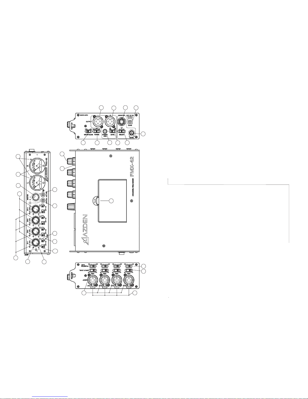
“INPUT LEVEL” Settings: “+4”, “-30 dBu”, “-50 dBu”
EachinputchanneloftheFMX-42hasitsownlevelsetting(7).Selecttheinputlevel
thatisbestsuitedforthemicrophone,wirelessreceiverorline-levelaudiocompo-
nentthatyouareconnectingtoeachinput.The“+4”settingisforline-levelaudio,“-
30dBu”and“-50dBu”arebothmicrophone-levelsettings.Forthemicrophone-
levelsettings,startwiththe“-30dBu”position.Ifyourmicrophoneseemstohavetoo
muchgain(volume)trythe“-50dBu”setting.
“PHANTOM DC48V” Switch:
EachchanneloftheFMX-42has itsown “PHANTOMDC48V”powersetting(8).
Whenusingadynamicmicrophonebesuretoturnthecorresponding“PHANTOM
DC48V”switchtothe “OFF” position.Whenusingacondenser microphone that
requires 48VDC external power, turn the corresponding “PHANTOM DC48V”
switch to the “ON” position. The “PHANTOM DC48V” only opterates in the “-30
dBu”and“-50”“INPUTLEVEL”position
WARNING: With the “PHANTOM DC48V” power turned “ON” the FMX-42 supplies
48VDC to the microphone. Please make sure that your microphone is designed to
handle48VDCoryou may damage it. Checkthe microphone’suser manual orwith
themanufacturer of yourmicrophone.
FRONT PANEL CONTROLS and SETTINGS
Input “LEVEL” Controls:
Each“INPUT”channeloftheFMX-42hasanadjustableinput“LEVEL”control(9)
(thisistheinner-smallercontrol).Thiscontrolstheinputvolumeofthemicrophone
connected to each corresponding “INPUT”. Zero is the lowest (quietest) setting
while10isthehighest(loudest).Forthebest soundwiththelowestnoise,increase
theinputlevelcontroluntilthecorrespondingVUMeter(10)peaksat0dB.
Input “PEAK” Level LEDs:
Each“INPUT”channeloftheFMX-42has2“PEAK”levelLEDs.TheseLEDsare
providedtohelpsetpreciseinput“LEVEL”adjustments.TheLEDsarelocatedtothe
leftofeachinput“LEVEL”control.ThelowerLED(11)indicatestheleveloftheinput
electronicallypriortothe“LEVEL”control.TheupperLED(12)indicatesthelevel
electronicallyafterthe“LEVEL”control.ThelowerLED(11)lightingREDindicates
thattheitemattachedtothemixer’s“INPUT”hasasignalthatistoohighandshould
bereducedeitherbychangingthe“INPUTLEVEL”switch(7)oratthedeviceitself.
Theupper“PEAK”level LED(12) shouldonlylightREDoccasionally.IfthisLED
stays lit continuously lower the input “LEVEL” (9) and/or change your “INPUT
LEVEL”(7)settings.TheseLEDshelpreducesignaloverloadanddistortion.
“PAN” Controls:
EachchanneloftheFMX-42hasanadjustable“PAN”control(13)(thisistheouter-
largercontrol).Whenthe“PAN”controlisinthecenterposition,anequalamountof
soundwillcomefrom“OUTPUT”“L” (14) and “OUTPUT” “R” (15) foranymicro-
phoneorline-levelinputconnectedtothecorresponding“INPUT”.Movingthe
23
“PAN”controlleftwilldecreasethesoundoutputinthe“R”ightchannel.Movingthe
“PAN”controlrightwilldecreasethesoundoutputinthe“L”eftchannel.
“LIMITER” Switch:
Each “INPUT” channel of the FMX-42 has a switchable “LIMITER” (16). After
settingtheinput“LEVEL”,turnthisswitchto“ON”.The“LIMITER”circuitactsasa
safety and reduces the possibility of overload distortion from very loud sounds
withoutaffectingnormalsoundvolume.Ifyouprefertheoverallsoundqualityofthe
mixerwithoutthe“LIMITER”circuitengagedleavetheswitch“OFF”.
“HPF” - High Pass Filter:
Each“INPUT”channeloftheFMX-42hasaswitchablehighpass(lowcut)filter-
“HPF”(17).Thisfilter is useful for removing unwanted low frequencies, suchas
windandair-conditioningnoise.Formostapplicationsengagingthehighpassfilter
willimproveoverallsoundquality.
“MASTER” Level Control:
The “MASTER” knob (18) controls the overall volume of all connected sources
(microphonesand/orline-leveldevices).Forthebestpossiblesoundandlowest
noise,trytokeepthiscontrolsetatitsmidpointwhilemaintainingtheVUmetersat
their0dBrangewiththe“input“LEVEL’controls.
VU Meters - “L” and “R”
Forthebestsound,whilekeepingthe“MASTER”controlatitsmidpoint,increaseor
decreaseeachchannels“LEVEL”control(9)untilthe“L”and/or“R”VUmeter(10)
peaks at 0 dB. If the ”LEVEL” is set too low, sound may be accompanied by
backgroundhiss.Ifthe“LEVEL”issettoohighthesoundmaybedistorted.Monitor
thesoundwithheadphonesandadjustthe“LEVEL”forthebestsound.Apeaklevel
LED(19) willlightREDifyouroveralllevelsaresettoohigh.
“SLATE MIC”:
Press and hold this button (20) to engage the “SLATE MIC” (microphone).The
“SLATEMIC”isusedtopickupaudioatthemixer’slocationandisnotintendedfor
seriousaudiorecording.Itishowever,veryusefulfornotatingscenesorotheron-
locationdocumentation.
“1 kHz TONE”:
Pressandholdthisbutton(21)togeneratethe1kHztone.Thisoutputtoneisused
tosettherecordinglevelsofyourvideocameraoraudiorecordertotheiroptimum
level.Whilegeneratingthe1kHztone,settherecordinglevelsofyourvideocamera
oraudiorecordertothespecifiedlevelasrecommendintheowner’smanual.The
signalisgeneratedat+4dBu.
Other Azden Mixer manuals