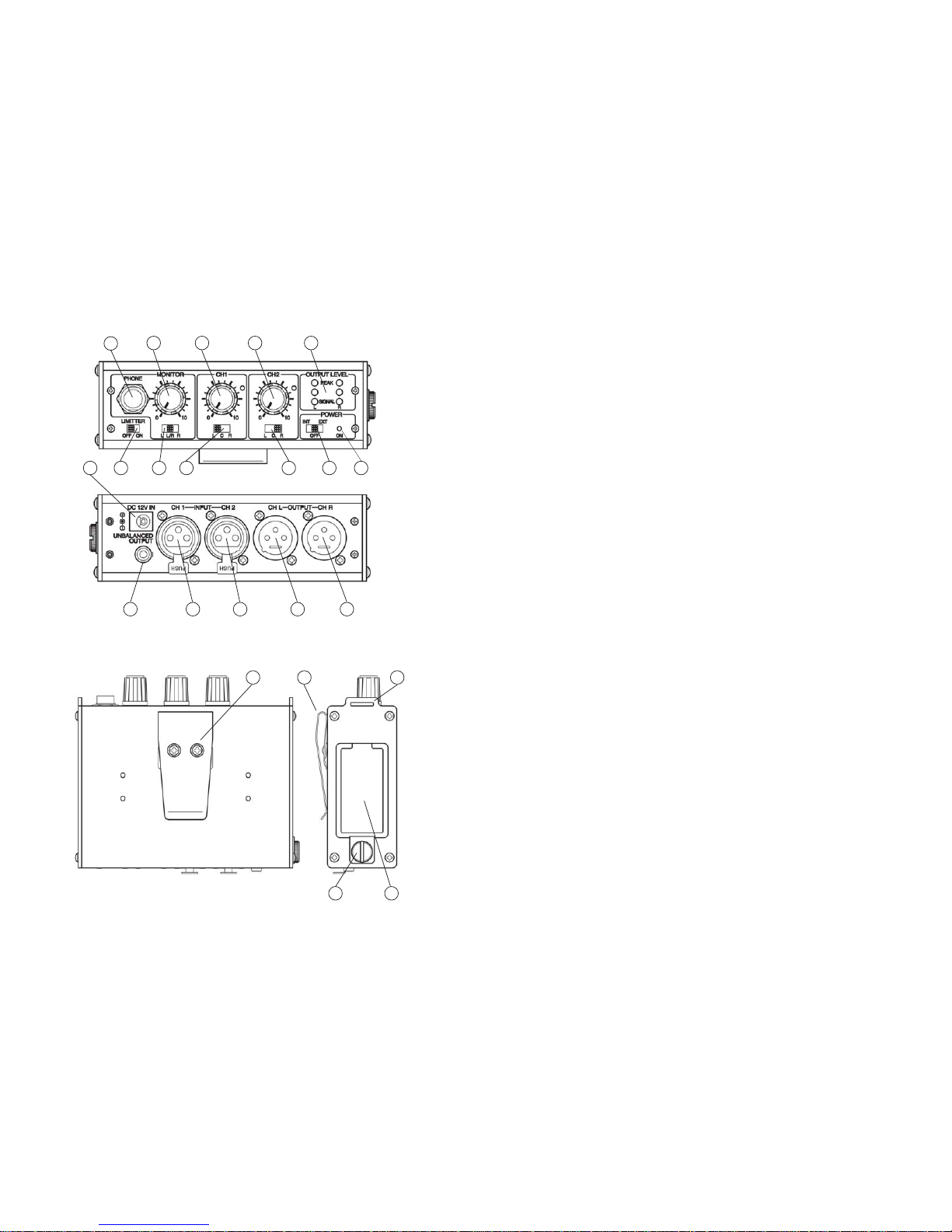
CH2(4):Controlstheinputlevel(volume)ofthemicrophoneconnectedtoInput CH2(13).
Zeroisthelowest(quietest)setting,10isthehighest(loudest).Forthebestpossiblesoundand
lowestnoiseincreasetheinputlevelcontroluntiltheinputLEDlightsoccasionally.
OUTPUT LEVEL LED INDICATORS (5)
For the best sound increase the INPUT LEVEL of CH1 (3) and/or CH2 (4) so that the
correspondingPEAKLEDindicator(5) flashesredoccasionallyduringtheloudestpartsof
whatyouarerecording. Iftheindicatordoesnotlightitmeansthattheinput(volume)levelis
too low and the sound may be accompanied by background hiss. If the indicator is lit
continuouslyitmeansthattheinput(volume)levelistoohighandthesoundmaybedistorted.
Monitorthesoundwithheadphonesandadjusttheinputlevelsforthebestsound.
OUTPUT SELECT CH A (6) and CH B (7)
Bysettingthe OUTPUT SELECT switch(6)and/or(7)toLthesound ofanymicrophone
pluggedintothecorresponding INPUTCH1(12)and/orCH2(13)willbesenttoOUTPUT
CHL(14). IfusingtheUNBALANCEDOUTPUT(16)thesoundofthismicrophonewillbe
senttotheleftchannel.
Bysettingthe OUTPUTSELECTswitch (6)and/or(7) toCthesoundofanymicrophone
pluggedintothecorresponding INPUTCH1(12)and/orCH2(13)willbesenttoOUTPUT
CHL (14)andOUTPUT CHR(15). IfusingtheUNBALANCEDOUTPUT(16)thesound
ofthismicrophonewillbesenttotheleftandrightchannels.
Bysettingthe OUTPUTSELECTswitch (6)and/or(7) toRthesoundofanymicrophone
pluggedintothecorresponding INPUTCH1(12)and/orCH2(13)willbesenttoOUTPUT
CHR(15). IfusingtheUNBALANCED OUTPUT(16)thesoundofthismicrophonewillbe
senttotherightchannel.
MONITOR CONTROL (11) and MONITOR OUTPUT (10)
TheMONITORcontrol(11)adjuststhevolumelevelofheadphonesconnectedtotheMONITOR
output(10). Zeroisthelowest(quietest)setting,10isthehighest(loudest).
MONITOR SELECTOR SWITCH (#9)
Normally,settheMONITORselector(9)topositionL/R. IntheL/Rpositionyouwillmonitor
thesoundofallconnectedmicrophonesusingeitherstereoormonoheadphones.Ifyouonly
wanttoheartheoutputfromCH L,usestereoheadphonesandsettheswitchtopositionL.
Or,ifyouonlywanttoheartheoutputfromCHR,usestereoheadphonesandsettheswitch
topositionR.
LIMITER SWITCH (8)
After setting the Input Levels, turnthis switch to ON.Thelimitercircuitreducespossible
overloaddistortionfromveryloudsoundlevelswithoutaffectingnormalsoundlevels.Ifyou
prefertheoverallsoundqualityofthemixerwithoutthelimitercircuitengagedleavetheswitch
OFF.
INPUT CH 1 (12)andCH 2 (13)
ConnecttheoutputofamicrophoneorwirelessreceivertoINPUTCH 1(12) and/orCH 2
(13). Theinputsacceptastandard3-pinmale XLRconnectorequippedcable. Pushthe
connectorintotheinputjackuntilitlocks. Toremovetheconnector,pressthePUSH taband
pull out the connector. For a more detailed description of how INPUT CH 1 (12) and
INPUT CH 2 (13) work see OUTPUT SELECT above.
OUTPUT CH A (14) and CH B (15)
ConnectacablefromOUTPUTCH A(14)and/orCHB(15)tothemicorlineinputofyour
videocameraoraudiorecorder. Theoutputsacceptastandard3-pinfemaleXLRconnector
equippedcable. Pushthecableconnectorintotheoutputjackuntilitlocks,andtoremovethe
connector press the release tab on the connector and pull out. For a more detailed
description on how OUTPUT CH A (14) and CH B (15) work see OUTPUT SELECT
above.
UNBALANCEDOUTPUT(16)
This output is stereo (dual-channel). It is recommended to use a stereo-to-stereo mini-
cable(notsupplied)fromtheUNBALANCEDOUTPUT(16)tothemicorlineinputofyour
videocameraoraudio recorder. TheUNBALANCE OUTPUT (16)isdesigned for video
camerasoraudiorecorders,whichhavemini-jackmicrophoneorlineinputs. Becausethe
FMX-20haslow-impedanceXLRinputsandamini-plugoutput,usersofminiDVcameras
that have mini-plug microphone inputs can now use high-quality microphones with XLR
outputs. For a more detailed description on how the UNBALANCED OUTPUT (16)
works see OUTPUT SELECT above.
DC12V Input(17)
Forexternalpoweringofthemixerconnectapowersupplytothisinput.Maximumrating
ofthepowersupplyshouldnotexceed12volts,350mA.