Aztech DieMaster DM-40 series User manual

DIE MASTER
User Manual
DM-40XX
AZTECH CONVERTING SYSTEMS
212 W Lodge Drive
TEMPE, AZ 85283
PHONE (480) 951-8351
FAX (480) 998-5409
www.aztechconverting.com
Ver 1.3

AZTECH CONVERTING SYSTEMS
DM-40XX
USER MANUAL
TABLE OF CONTENTS
SECTION 1: GENERAL INFORMATION 1-4
SECTION 2: MACHINE INSTALLATION 4-5
SECTION 3: MACHINE SETUP 6-18
SECTION 4: MACHINE OPERATION 19-28
SECTION 5: MAINTENANCE 29
SECTION 6: STATION DETAIL 30-52
SECTION 7: TROUBLESHOOTING 53
SECTION 8: WARRANTIES AND SERVICE 54

AZTECH CONVERTING SYSTEMS
DM-40XX
USER MANUAL
1
Section 1: General Information
1-1: Introduction
The AZTECH DieMaster Rotary Die Cutting Machine is available in 13 inch (33.02 cm), 18 inch
(45.72 cm) and 20 inch (50.8 cm) widths, with dual-spindle rewinds, and web speeds up to 500
feet/minute. The DieMaster is designed to be highly productive, versatile, and simple to operate
and maintain. Before operating your new DieMaster, fully read and understand all facets of this
manual. Following the procedures outlined in this manual will help assure maximum performance.
Keeping your machine properly set-up and maintained will assure years of productive and satisfac-
tory service.
1-2: Machine Information and Specications

AZTECH CONVERTING SYSTEMS
DM-40XX
USER MANUAL
2Rev 1.3
FRONT LAYOUT
(DIE MASTER ONLY)

AZTECH CONVERTING SYSTEMS
DM-40XX
USER MANUAL
3
SIDE LAYOUT
(DIE MASTER ONLY)
(13” Shown, 18” and 20” are
similar)

AZTECH CONVERTING SYSTEMS
DM-40XX
USER MANUAL
4Rev 1.3
1-3: Care and Maintenance
To assure maximum performance and longevity of your Die Mas-
ter, it is very important to perform periodic maintenance. Read
Chapter 5 for more information.
1-4: Safety
The DieMaster is designed to operate at high rates of speed, employing rollers, gears, pulleys, and
other moving parts. Where possible, guards are provided to protect operator from injury. Operators
must keep their hands clear of the machine when it is in operation. Making all operators aware of
potential safety hazards will help minimize any chances of operator injury.
Section 2: Machine Installation
2-1: Preparation
It is important that your DieMaster Rotary Die Cutter be situated on solid and level ground. Make
sure that site allows for access to machine from all 4 sides. If the machine is placed on unstable or
un-level ground, it may tip over risking damage or serious personal injury.
2-2: Un-crating Machine
To avoid damage to your new DieMaster, begin by unfastening the latches on the front panel and
removing the panel to expose the machine. Carefully remove all boxes from inside the crate and
set aside to avoid damage. Remove all 4 lag bolts which hold the machine to the base.
2-3: Removal and Positioning
It is critical that the DieMaster be removed from the crate using a fork lift, making sure that the forks
t directly inside the 2 slots at base of the machine. Lift and remove from crate, and if equipped with
adjustable feet, thread all 4 feet into threaded holes at machine’s base, and lower into desired posi-
tion. Machine may be leveled by turning adjustable feet until level.
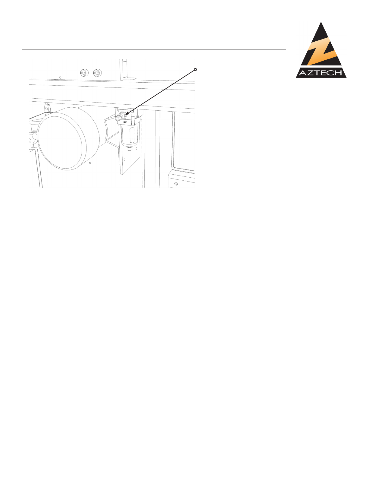
2-4: Electrical and Pneumatic Connections
ELECTRICAL CONNECTIONS: Your DieMaster uses
a power supply of 220 volts, 50 amps AC 3PH. Im-
proper connections or mishandling may cause seri-
ous personal injury. AZTECH highly recommends that
electrical service be performed only by a qualied
electrician.
Electrical connection to the machine is performed
by bringing electrical service to the electrical box at
the back of the machine and making connections as
shown.
50A 220VAC
THREE PHASE
TO DISCONNECT

AZTECH CONVERTING SYSTEMS
DM-40XX
USER MANUAL
5
90PSI
INCOMING
HP AIR
PNEUMATIC CONNECTIONS: Although
your machine has been thoroughly tested
before shipment, connections on occasion
may loosen during shipment. Visually inspect
all pneumatic to assure that each is tted
securely. Connect airline to the pneumatic
control panel at the back of the machine (see
gure 2-B), and listen for any air leaks that
may exist. Check all switches by switching
back and forth from on and off to make sure
they are operating properly.
NOTE: Red lines on air dials indicate proper default settings.
2-5: Testing Before Operation
Make sure the area around your machine is clear of any objects which may impair the machine.
Also inspect and make sure all belts, pulleys, rollers, and spindles are free and clear of any
objects which may impede operation, and risk machine damage. Before threading your machine,
accelerate and decelerate your machine through a full range of speeds, and make sure acceler-
ation is smooth and free of any unnatural sounds or movements. Using control switches, switch
Unwind and Rewind Spindle(s) from on and off positions making sure the pneumatic system is
performing properly. Then turn power on, run machine at low speed to assure machine is working
properly. Then with speed set at maximum setting, press the stop button to assure that the brake is
working properly.

AZTECH CONVERTING SYSTEMS
DM-40XX
USER MANUAL
6Rev 1.3
Section 3: Machine Setup
3-1: Webbing the Machine
Proper webbing of your DieMaster is vital to optimal machine performance. The proper way to
thread your machine for various substrates is shown on the following page. Any improper webbing
of the machine may cause tension problems that will impede operation.
To web the machine:
1. Turn unwind arbor switch to
“DEFLATE” position.
2. Assure that the rewind and
unwind switches on main pan-
el are in the “OFF” position
3. Assure that both splice-table
clamps are released into the
up position.
4. Assure that the pneumatic nip
roll is disengaged in the up
position.
5. Assure that the slitting blades
are disengaged. BE SURE
TO USE CAUTION WHEN
NEAR RAZOR SLITTING
BLADES AS THEY ARE
EXTREMELY SHARP AND
MAY CAUSE SERIOUS INJURY.
6. Load roll onto unwind spindle and carefully thread the web through the machine making sure to
follow web paths on the following page.
Modular Design
The Die Master press is designed
in modular sections to allow a
press to be tailored for an appli-
cation. The various sections are
shown on the following pages.

AZTECH CONVERTING SYSTEMS
DM-40XX
USER MANUAL
7
Unwind Sections
Cradle Mount
Unwind
CMU
Unwind Disc Brake
UDB

AZTECH CONVERTING SYSTEMS
DM-40XX
USER MANUAL
8Rev 1.3
Lamination Tower
Flexo Print Station
ACCESSORY MODULES

AZTECH CONVERTING SYSTEMS
DM-40XX
USER MANUAL
9
13” - 18” DIE MASTER
20” DIE MASTER
DIE SECTIONS

AZTECH CONVERTING SYSTEMS
DM-40XX
USER MANUAL
10 Rev 1.3
DieMaster w/ UDB Web Path
13” Die Master Shown
-UDB
-Print Station
-Lamination Tower
-13” Die Section
UDB
PRINT STATION

AZTECH CONVERTING SYSTEMS
DM-40XX
USER MANUAL
11
LAMINATION TOWER
REWIND MODULE
UNDERSCORE
OPTIONAL WEB PATHS
SHOWN DASHED

AZTECH CONVERTING SYSTEMS
DM-40XX
USER MANUAL
12 Rev 1.3
SAMPLE 20” PRESS
CMU INFEED NIP
PRINT STATIONS
13” Die Master Shown
-CMU
-2x Print Stations
-Lamination Tower
-20” Die Section

AZTECH CONVERTING SYSTEMS
DM-40XX
USER MANUAL
13
20” DIE SECTIONS
Lamination Tower
OPTIONAL WEB PATHS
SHOWN DASHED

AZTECH CONVERTING SYSTEMS
DM-40XX
USER MANUAL
14 Rev 1.3
3-2: Web Guide Setup
The web guide is located in the center of
the machine between the unwind and re-
wind stations. After webbing the machine,
set the web by doing the following:
Setting the Web Guide:
1. Press the “SERVO-CENTER” button on the
front of the web guide.
2. Align the sensor with the inside edge of the
web. For ne alignment adjustment, turn
knob on outside of web guide.
3. Jog the machine briey to assure that the
web is moving smoothly.
4. Press the “AUTOMATIC” button which
will engage the sensor and allow the web
guide to adjust itself to the movement of
the web.
5. For more specic instructions about the
features of the web guide, refer to the Ac-
cu-Web manual included with this manual.
COARSE
SENSOR
POSITIONING
FINE
SENSOR
POSITIONING
3-3: Nip Roll Operation
The Nip Roll is pneumatically controlled using control switch and
must be in the up position while machine is running, and in the
down position when threading machine.
AUTOMATIC SERVO CENTER

AZTECH CONVERTING SYSTEMS
DM-40XX
USER MANUAL
15
3-4: Splice Table Operation
The splice table on your Sidewinder BSR is located just above the
Unwind Station, just after the optional Inspection Tower. To operate
the Splice Table, simply follow the following steps:
1. Turn off machine and engage both web clamp switches.
2. Using a razor blade, carefully cut the web along the slicing channel. Disengage the clamp near-
est the unwind station. Be sure to leave the other clamp engaged.
3. After waste has been removed, pull through new web, carefully align with web, and lower the
handle to hold.
4. Again using a razor blade, cut the web, discard waste, pull tape under webs, fold to secure and
cut tape.
5. Disengage both switches to release web clamps.
SLITTING CHANNEL
WEB CLAMP
SWITCHES

AZTECH CONVERTING SYSTEMS
DM-40XX
USER MANUAL
16 Rev 1.3
3-5: ROTARY SHEAR SET-UP
Step 1 Set lower blades for
desired slit-widths and tighten
set-screws, making sure upper
blades are up and not in lock
position.
Step 2 Lower upper blade
assembly by turning handle
counter-clockwise and snap
into lock position, making sure
that the upper blades are clear
of lower blades to avoid blade
damage.
Step 3 Gently slide upper
blade(s) into cutting position
ush against the lower blade(s)
by pushing on both sides of the
blade to avoid wobble. Hold up-
per blade against lower blade
and tighten set-screw.
TURN TO UNLOCK
SLITTER
TIGHTEN SET SCREWS
TO LOCK BLADES

AZTECH CONVERTING SYSTEMS
DM-40XX
USER MANUAL
17
SLIDE FORWARD
TO REMOVE
3-6: Changing Rewind Spindle
Your Die Master may be equipped with Convertech pneumatically inatable modular rewind spin-
dles. These spindles are easily removed by loosening the hex-screw at the machine side and pull-
ing away from machine. To insert new spindle, simply insert spindle into rewind station and tighten
hex-screw rmly.
CAUTION: Utilizing Rewind Spindles less than 1.5” in diameter require the use of Outboard
Support Apparatus which is NOT included in the standard equipment. Operating the ma-
chine without the support apparatus and with spindles less than 1.5” may result in serious
injury.
LOOSEN SET
SCREW HERE

AZTECH CONVERTING SYSTEMS
DM-40XX
USER MANUAL
18 Rev 1.3
3-7: End-of-Roll (EOR) Sensor Adjustment
The unwind unit will come equipped with an end-
of-roll sensor. When this sensor is switched on,
the machine will not RUN if there is insufcient
material on the unwind roll. To adjust the sensor:
1: Loosen the screw retaining the EOR sensor
mount.
2: Move the sensor into a position where it is just
“OFF” with an empty core.
3: Tighten the retaining screw.
LOOSEN SET
SCREW HERE
ADJUST EOR HEIGHT
ADJUST EOR HEIGHT
CMU EOR Sensor Mounting
UDB EOR Sensor Mounting
Table of contents