Binding Products GuilloMax User manual

1
GuilloMax
GuilloMaxGuilloMax
GuilloMax
User Manual
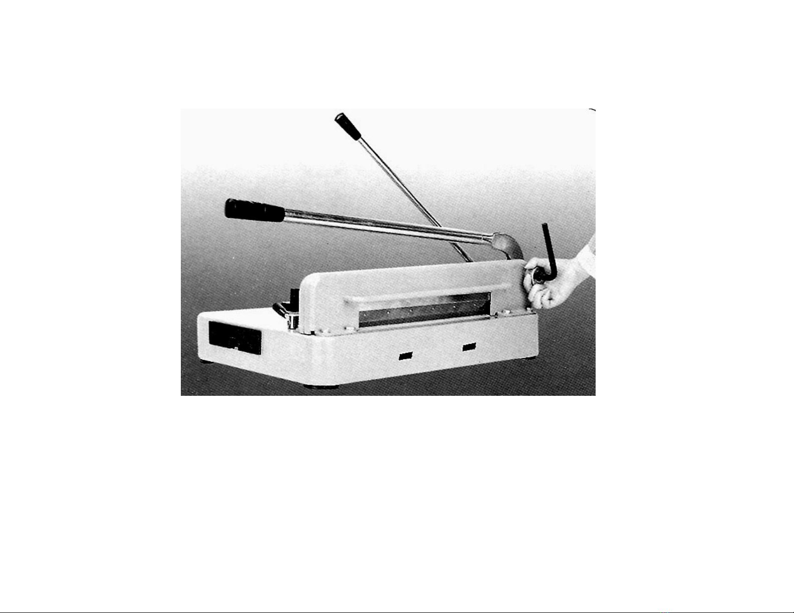
The Guillomax has distinct features such as its unique structure and ease of cutting. It combines symmetry with
functionality with the necessary maintenance tools stored in a convenient built in tool box, as well as arallel handles for
its a er clam and blade handle that are close to each other for easy two handed o eration even by just one user. The
heavy duty construction is sim le yet efficient with minimal moving arts for easy maintenance. The cutting blade is
extremely shar , so several safety features are included with the machine, such as a blade handle lock, blade guard
and a unique blade holder that enables the user to handle the blade without actually touching it directly.
Cutting Preparation
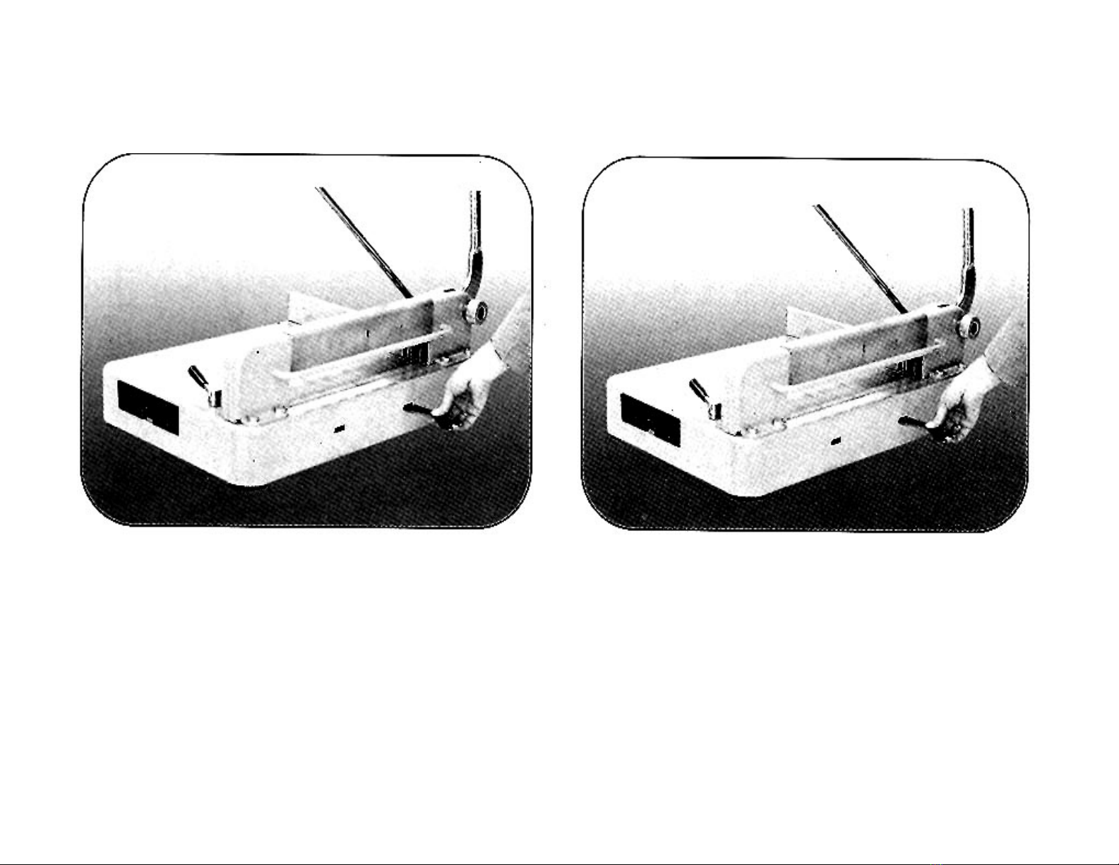
Place the handles for both the blade and the clam all the way u . Doing this with the blade handle locks it in lace.
The blade handle lock can be released by holding down the lock release on the base of cutter while bringing down the
handle.
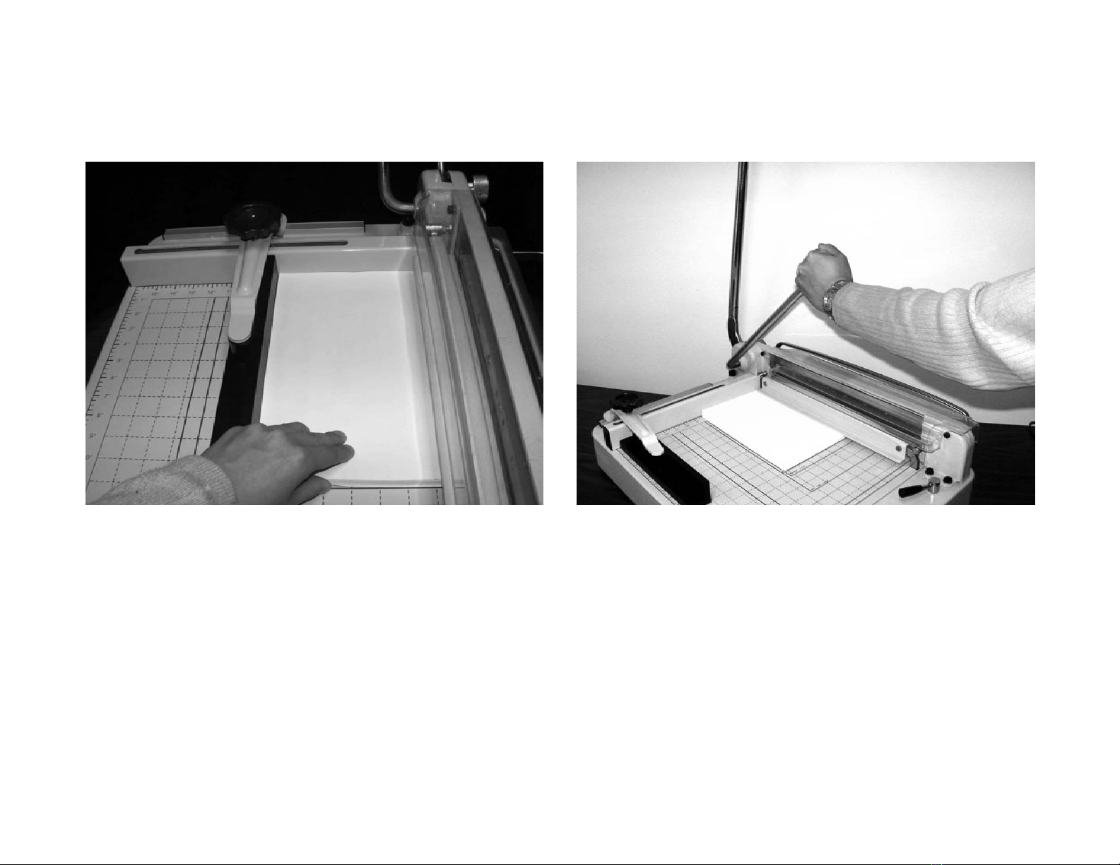
With the blade handle in the locked osition, set the a er stack against the alignment guides for the to and side of the
stack. As soon as the a er stack is set under the cutting blade based on the desired osition, ull the clam handle
down on the stack and secure it by ressing down on the handle to lock the stack in lace. Unlock the blade handle and
ull down to start cutting.
Remember to ush the handle all the way u and lock it to secure the blade in a safe osition when the cutter is not
being used.
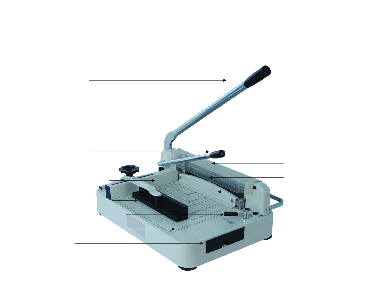
Parts: Tools Included:
1. Blade handle 1. Blade holder
2. Clam handle 2. S are cutting bar
3. To alignment guide 3. Blade guard
4. Side alignment guide 4. ½” allen wrench
5. Cutting blade 5. Phili s screw driver
6. Pa er clam 6. S are screws
7. Tool box
8. Blade handle lock release
9. Cutting base
10. Blade cradle

2
GuilloMax
GuilloMaxGuilloMax
GuilloMax
Blade Handle
Blade Handle Lock Release
Top Alignment Guide
Side Alignment Guide
Clamp Handle
Paper Clamp
Tool Box
Blade Cradle
Cutting Base
Cutting Blade

3
Operating Procedures
Operating ProceduresOperating Procedures
Operating Procedures
Push the blade lever all the way u until it reaches a 90 degree angle. Sto when you hear a
clicking sound. This means that the lever is locked in lace.
Step 1

4
Step 3Step 2
Align bar into the chosen size and tighten the screw by
turning clockwise.
Choose desired size that you want to cut.

5
Step 5Step 4
Pull down clam lever to lock a er in.Insert a er.

6
Step 7Step 6
Press the clam lever to secure the a er before ressing
down the blade handle.
Make sure to lock the handle again before releasing the
a er.
Press and hold to release safety lock for the blade
handle.

7
Changing the Cutting Stick
In order to rotect the blade from undue wear, the cutter is equi ed with a cutting stick that is
made of hard lastic. It is ositioned right under the cutting s ace of the blade to act as a cutting
sto er reventing the blade from touching any metal art of the base. To make this stick last
longer, you can rotate the stick to a new side that gets in contact with blade. The first thing to do is
to install the blade guard, with the arrow ointing u , onto the blade’s cradle (See Fig. 1). Hook the
to art of the guard onto the cradle first and ress on the bottom art until you hear a click sound.
This rotects whoever is changing the blade or the bar from getting accidentally cut by the ex osed
blade.
ig 1

8
Changing the Cutting Stick
ig 2 ig 3
After installing the blade guard, take out the blade holder and insert the smaller end at about a 45 degree angle
with the arch facing down into the first hole from the right side of the base. From this osition, move the holder
in a downward motion until the cutting bar o s out (See Fig. 2-3).

9
Changing the Cutting Stick
ig 4 ig 5
You can then rotate the bar 90 degrees and reinsert it into its recessed slot to change the side the meets with
the blade when cutting (See Fig. 4). You can do this for all sides and on both ends of the bar. An extra bar is
also rovided in the tool box. To remove the blade guard, sim ly ull the to art backward from the cutter
cradle (See Fig. 5)

10
Adjusting the Blade
ig 6
After changing the blade or the cutting stick, or if the blade starts to cut unevenly, you might need to
adjust the balance of the blade. To do this, take out the ½” allen wrench and loosen the blade adjustment
knob located at the right side of the cutter by the base of the blade. With the blade handle down, turn the
allen wrench counter clockwise. To adjust the blade, you need to turn the knob by hand until balance is
achieved. To check for balance, the blade should be resting evenly along its length on the rotective
cutting bar. Turn the allen wrench clockwise to relock the blade in lace (See Fig. 6).

11
Changing the Blade
ig 7
Change the blade whenever necessary. First, with the clam handle u , ull the blade handle down
to ex ose the first screw attaching the blade to its cradle (See Fig. 7).

12
Changing the Blade
ig 8 ig 9
Remove the said screw using the Phili s screwdriver. Lift the blade handle back u to its locked osition
and ull the clam handle down. Using the s are screws and the Phili s screwdriver, install the horned
end of the blade holder to the two ex osed holes in the middle of the blade. While holding the blade
holder, remove all the remaining screws that attach the blade to its cradle, making sure to remove the
screw in the middle of the blade last of all (See Fig. 8). To remove the uninstalled blade, slide it
downwards from the front and out of the cradle (See Fig. 9).
To install a new blade, follow the instructions in reverse order, making sure each screw is tightly installed.
Table of contents