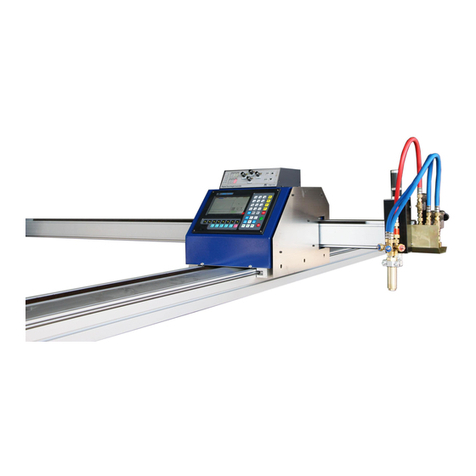
ARCBRO Stinger-PRO 5100 Series Manual

Service Support Spirit
Unique Solution WWW.ARCBRO.COM
1
Stinger-PRO5100 SERIES
High Definition Cutting Machine install Manual
Operator Manual
ARCBRO| Revision 2 | English
Date of issue: August, 2020

Service Support Spirit
Unique Solution WWW.ARCBRO.COM
2
Technical Support
Thank you very much to choose ARCBRO product, our whole engineer department work for
you since the day you receive machine. When you have any questions during assembling or
operating, it is free to contact us by Call, Email, Online help 7x24 hours.
Wish you enjoy a wonderful CNC cutting travel.
ARCBRO CNC Technical Support & Solutions
7x24 Hours
+86-10-65798995
support@arcbro.com
www.arcbro.com/about-arcbro-cnc-cutting-solutions/

Service Support Spirit
Unique Solution WWW.ARCBRO.COM
3
Changes may be made periodically to the information in this manual without
obligation to notify any person of such revisions or changes. Such changes
will be incorporated in new editions of this manual or supplementary
documents and publications. This company makes no representations or
warranties, either expressed or implied, with respect to the contents hereof and
specifically disclaims the implied warranties of merchantability or fitness for a
particular purpose.
No parts of this manual may be reproduced, stored in a retrieval system, or
transmitted, in any form or by any means, electronically, mechanically, by
photocopy, recording or otherwise, without the prior written permission of
ARCBRO Company.
This User’s Manual is only available for Stinger-PRO CNC Plate Cutting
Machine.
Ensure that the operator has read and understood this User’s Manual before
any operation on Stinger-PRO CNC Plate Cutting Machine.
There may be few differences between the pictures in this User’s Manual and
the machine you received.
Never hesitate to contact us for on-line technical service when you have any
questions or you need help, and it's our pleasure to be there for help.

Service Support Spirit
Unique Solution WWW.ARCBRO.COM
4
Contents
Technical Support............................................................................................................................2
Technical Parameters......................................................................................................................5
Notes ...............................................................................................................................................6
Safety...............................................................................................................................................7
1.Information for your safety ...................................................................................................7
1. Stinger-PRO Description ..........................................................................................................9
1.1. What is Stinger-PRO.........................................................................................................9
1.2. Application........................................................................................................................9
1.3. Programming and Nesting...............................................................................................9
2. Packing List ...............................................................................................................................10
2.1. Introduction.....................................................................................................................10
2.2. Packing List ....................................................................................................................10
3. Installation .................................................................................................................................11
3.1 Mechanical Assemble Steps ..........................................................................................11
3.2 Basic assemble steps:....................................................................................................12
Step: Unpack the equipment box and remove all items .....................................................13
Step 1: Assemble the legs of the Gantry Frame ..................................................................15
Step 2: Installation of dust extraction table. .........................................................................17
Step 3: Assemble each Side Board onto the frame leg ......................................................18
Step 4: Assemble electrical box. ..........................................................................................19
Step 5: Assemble CNC System screen................................................................................20
Step 6: Adjust the flatness of the machine...........................................................................21
Step 7: Plasma cutting part assemble. ................................................................................22

Service Support Spirit
Unique Solution WWW.ARCBRO.COM
5
Technical Parameters
Type
Stinger-PRO 5100
Effective cutting range 1500x3000mm
Actual machine size 4150x2210x1600mm
Input power supply 1 phase, 110V, 220V, 50Hz/60Hz
Input capacity 3600W
Cutting model High definition Plasma cutting
Max travel speed 20000mm/min
Drive motor Servo motor
Reducer 3 reducer
CNC SYSTEM
Display 15’’ color LCD screen
CPU IPC
External format TXT or NC format
Language English, Spanish, Russian, French, Japanese, Czech, Slovenia
PLASMA CUTTING MODE
Max cutting speed 15000mm/min
Max cutting thickness Depends on plasma power source
Plasma power source Support up to High definition plasma
THC Arc voltage Auto Torch Height Controller
Accuracy ±0.3mm

Service Support Spirit
Unique Solution WWW.ARCBRO.COM
6
Notes
Note 1: Propane cutting nozzles are included in standard package. Acetylene nuzzles can be
ordered.
Note 2: Specific torch assembly must be ordered for Gasoline project.
Note 3: Nesting software standard Wizard is included in standard package.
Note 4: The machine must be grounded reliably when it is working. (Connect the plate and the
earth)
Note 5: Clean dust regularly to keep the rail and rack clean for smooth movement.
Note 6: Avoid damage for the LED display screen of CNC system.
Note 7: Equipment use environment:
Ambient temperature: -10℃—+50℃
Environment humidity: 90﹪RH below
Storage temperature: -20℃—+65℃
Sea level elevation: An altitude of 1000 m below

Service Support Spirit
Unique Solution WWW.ARCBRO.COM
7
Safety
1.Information for your safety
The operator must read and understood the contents of this user’s manual before any
operation on Stinger-PRO-PRO.
Never hesitate to contact us for assistance when you have any questions or you need help,
and you can reduce the account of time your troubles takes and solve your problem efficiently.
Note: Each of the following description must be verified before any operation.
- 1. The operator should wear face shield, welding gloves, caps, membrane filter dust mask and
sound insulation earmuff. It is strictly forbidden to observe directly or approach to the plasma
arc with exposed skin.
-2. The operator can’t load external program in internal storage
of the machine in case of the virus. Only the special software
recognized by ARCBRO can be applied.
-3. During cutting period, when the floating voltage is too high,
the operator should check the ground connection, neutral

Service Support Spirit
Unique Solution WWW.ARCBRO.COM
8
connection and insulation of the torch handle. Then isolate the workbench from the ground, Or
install no-load open-circuit relay in the electrical control system.
-4. The cutting operator and assistant must wear labor protection articles by regulation and take
safety measures to prevent electric shock, high-altitude falling, gas poisoning, fire or any other
accidents.
-5. The site should build rain-proof, damp-proof and sun-proof machine shed, and install
corresponding fire equipment. The machine should keep away from flammable and
combustible materials.
-6. As the operation and maintenance has potential dangerous, operator should be careful in
case getting injured. It’s forbidden to wear loosen cloths or cotton ropes in case being entangled
by the machine.
-7. The high voltage of plasma CNC cutter is fatal, so operator should install the machine step
by step as the manufacturer stipulate.
-8. Only trained personnel can be allowed to operate the equipment. Any maintenance should
obey the user’s manual and before that the power should be cut off. Only experience technicist
is allowed to change assemblies.

Service Support Spirit
Unique Solution WWW.ARCBRO.COM
9
1. Stinger-PRO Description
1.1. What is Stinger-PRO
Stinger-PRO-PRO pro 5100 ArcBro flagship true hole HD plasma CNC cutting table
launched in 2020. This robust, industrial table is built with production in mind. The plasma table
can handle the rigors of continuous production runs with industry leading repeatability and
reliability. And it has been designed and built from the ground up by ARCBRO engineer team-
ensuring a world class product with the quality and reliability you have come to expect.
It meet all the requirements of HD cutting, improve production efficiency, reduce operating
costs, comprehensively upgrade the cutting process, and build for all day production.
This one perfect plasma machine for every professional workshop own.
1.2. Application
Stinger-PROis an ideal CNC Plate Cutting Machine widely used in industry field, such as
shipbuilding industry, metallurgic industry, petrochemical industry and water resources &
electric power. It can cut various metal plates in seconds, for instance: carbon steel (flame
cutting), stainless steel, copper and aluminum (plasma cutting).
1.3. Programming and Nesting
Using ARCBRO plate nesting software, you can edit and do the nesting process for your
pattern designed by CAD, then generate a G-code cutting file in txt format. This txt cutting file
can be recognized and carried out by our CNC system when you import it by a USB drive. Now,
running Stinger-PRO, you can achieve accurate profiling of this pattern automatically.

Service Support Spirit
Unique Solution WWW.ARCBRO.COM
10
2. Packing List
2.1. Introduction
Stinger-PRO is packed carefully in one wooden boxes. All equipment in the boxes are
protected fully to avoid any damages during transportation.
The boxes have to be carried with care always and with the top cover up during handling
and transportation.
2.2. Packing List
Open the top cover of the boxes. And remove all the screws fixing the cover to the box body.
The Stinger-PRO transportation boxes contain:
This accessory is standard configuration, if your machine is customized, the accessories
are according to the order requirements.
The bolts of the machine are fixed to the machine.
Packing List:

Service Support Spirit
Unique Solution WWW.ARCBRO.COM
11
3. Installation
3.1 Mechanical Assemble Steps
This part describe how to install Stinger-PRO 1.5x3m portable CNC cutting machine step by
step.
Please assemble according to below steps carefully. Any questions or help needed, please
do not hesitate to contact ARCBRO after sale service engineer, we will provide help as soon as
possible.
The installer needs to prepare: electric drill, spirit level, forklift. Two installation
mechanical engineers are needed for faster installation.
In order to install the machine faster, please read the installation steps carefully
before installation, it will save installation time.

Service Support Spirit
Unique Solution WWW.ARCBRO.COM
12
3.2 Basic assemble steps:
Step 1: Assemble the legs of the Gantry Frame.
Step 2: Installation of dust extraction table.
Step 3: Assemble each Side Board onto the frame leg.
Step 4: Assemble electrical box.
Step 5: Assemble CNC System screen.
Step 6: Adjust the flatness of the machine.
Step 7: Plasma cutting part assemble.

Service Support Spirit
Unique Solution WWW.ARCBRO.COM
13
Step: Unpack the equipment box and remove all items
Remove all the screws which are fixed the box, check and confirm all the spare parts be
inside and well, and then move all the parts out safely.

Service Support Spirit
Unique Solution WWW.ARCBRO.COM
14

Service Support Spirit
Unique Solution WWW.ARCBRO.COM
15
Step 1: Assemble the legs of the Gantry Frame
Note: Install the machine carefully step by step as the following instructions:
The gantry frame assembly:
Assemble Step:
1. Lift the whole body from the
opposite of the drag chain
by Forklift( Mind the drag
chain and cables).
2. Install the leg to the frame.
The support legs and the
frame are marked with
serial numbers, please
install accordingly.
Forklift lifting location
1 2
2 3
2 3
1
1

Service Support Spirit
Unique Solution WWW.ARCBRO.COM
16
Assemble Step:
3. Connect and fix all legs onto the Gantry Frame by screw.
Note: Keep the machine stable.
Frame assembled

Service Support Spirit
Unique Solution WWW.ARCBRO.COM
17
Step 2: Installation of dust extraction table.
If the material table is an dust extraction table. Please refer to the step, the water table can
be ignored.
1-- Fix hopper onto dust extraction by screws.
NOTE: The hopper is too heavy and requires two people to install it.
In order to install simply, an installation engineer is required to install the hopper at the bottom
of the frame.
2--The two dust removal pipes of the hopper pass through the side board. Then connect to the
dust collector.
Hopper Hopper

Service Support Spirit
Unique Solution WWW.ARCBRO.COM
18
Step 3: Assemble each Side Board onto the frame leg
Fix each Side Board onto the frame leg by screws-4pcs. The Side Board and the frame are
marked with serial numbers, please install accordingly.
The Side Board assembled
2
2 2
1
1
1
6
6
6 1
2

Service Support Spirit
Unique Solution WWW.ARCBRO.COM
19
Step 4: Assemble electrical box.
1--Fix electrical box onto drag chain trough by screws;
The electrical box
Assemble Step:
1-- Fix electrical box
onto drag chain trough
by screws.
NOTE:
The electric
box is too heavy and
requires two people to
install it.
The electrical box assembled

Service Support Spirit
Unique Solution WWW.ARCBRO.COM
20
2--The sockets and cables of the electrical box are marked with serial numbers, please connect
the plugs accordingly;
Note: Note: No. 17 is a network cable, one end is connected to the system and the other
end is connected to the motion controller
Step 5: Assemble CNC System screen.
1-- Fix Screen support shelf onto frame by screws.
2-- Fix CNC System onto Screen support shelf by screws.
The motion controller
CNC System screen assembled
Table of contents
Other ARCBRO Cutter manuals
Popular Cutter manuals by other brands

Parkside
Parkside 327368 1904 Translation of the original instructions

Huskie Tools
Huskie Tools REC-434YC Operating instructions manual

RHYNO
RHYNO RHYNO2 Operator's manual

Milwaukee
Milwaukee M18 HCC75R Original instructions

Makita
Makita DSC121 Original instructions

Milwaukee
Milwaukee M12 2472-059 Operator's manual