the field at 0 and edit the batch later if necessary to add
length compensation. Once a value has been entered,
or if the default of 0 is to be used, press "Enter".
The next value is the quantity of cut pieces desired in
the run. Enter any value from 1 to 999,999. Press "En-
ter". The Rate Screen will now appear. Press the + or
- key to increment the feed rate from 1 to 5, or enter the
number of the desired feed rate if known. As the value
is changed, note that the rate values are automatically
updated to show the data relevant to the selected feed
rate. When the desired feed rate shows, press "Enter".
The Run Screen now appears. It shows the input-
ted length, quantity, feed rate, and compensation
value if used. If all parameters are correct, press
"Run" to start the run. The number of pieces left
will be updated as the run progresses. When the
run is complete a "Run Complete" message will ap-
pear on the display.
To interrupt a run at any time, press the "Esc/Pause"
key until the unit stops. The word "Paused" wil
appear on the display. The unit can be opened and
feed tension adjusted if necessary, then closed and
restarted by pressing "Run" or "Enter". While in
Pause, the length compensation and/or feed rate may
be edited, and material may be fed using the "Jog"
key and cut using the "Cut" key. To cancel the
remainder of a run while in Pause, press the "Esc/
Pause" key.
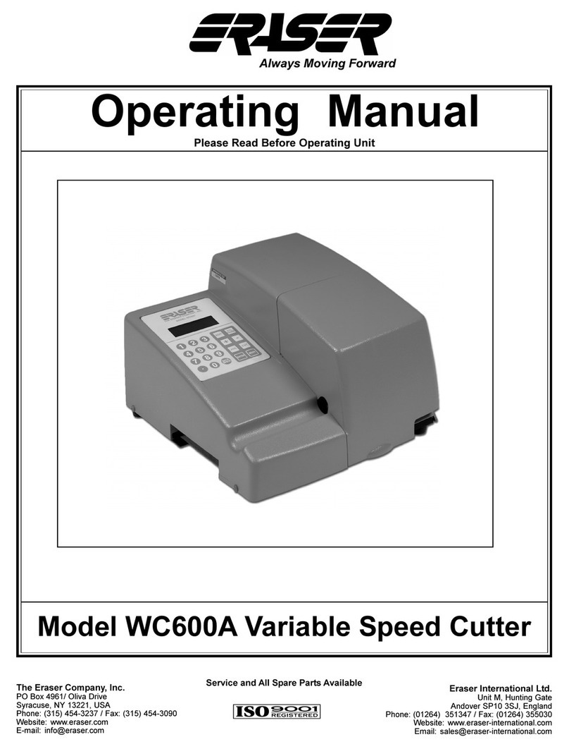
NOTE: The front cover of the WC600A must be com-
pletely closed in order for the unit to run. If the
cover is opened during a run the unit will stop and
display "Cover open/system disabled". The cover
must be closed, and the display will read "Ready to
run/any key continues". Press "Esc/Pause" to re-
turn to the Run Screen or "Run" to continue the run.
In the event of a power failure, the WC600A will stop
and will not restart automatically upon resumption
of power. The unit must be turned off and turned
back on again. All parameters stored in batch
memory will remain in memory, but any information
in a 0 batch that may have been running at the time
of the power failure will be lost.
Programming Note: If "Enter" is pressed before a
value is entered in a field, a long error beep will
sound. If a mistake is made in entering a value, use
the "BS" key to backspace over the entry. If "En-
ter" has not been pressed after a value is inputted,
press the "Escape/Pause" key and start over at the
field affected.
Blade Change or Replacement:
The WC600 is supplied standard with an angled tubing
blade installed, and a straight wire blade as an acces-
sory. The tubing blade must not be used on wire as
it will be severely damaged. The wire blade should
not be used on tubing as it will not give a square
cut. Optional special blade configurations are available
for applications that do not give good results with either
standard blade. Contact factory for details.
Caution: Be sure unit is unplugged and air cylinder
is disconnected before changing blades. Open the
front cover and locate the front of the exit chute. Loosen
the button head cap screw holding the exit chute, and
slide the chute to the right to remove it. Locate the
knuckle at the front of the air cylinder which holds the
blade. Remove the blade retaining pin by pulling out on
the knurled end. Slide the blade forward through the
blade block and remove. Caution: The blades are
extremely sharp, handle carefully to prevent injury.
To install a new blade, reverse the procedure. Once
the new blade is in, it may be necessary to adjust the
blade pressure. To do this, loosen the 1/2" nut and back
out the set screw using a screwdriver. To adjust, tighten
the set screw while sliding the blade back and forth until
some friction is felt. Then tighten the nut while holding
the screw in place. If the blade is too tight it will remain
in the forward position. Loosen again and readjust. Re-
install the exit chute and close the front cover.
Bushing Set Change or Replacement:
Caution: Be sure unit is unplugged and air cylinder
is disconnected before changing bushings. The
WC600A is supplied with three sets of bushings. For
the best cut results and accuracy, the entrance and exit
bushings should match the material size as closely as
possible. Therefore it may be necessary to change
bushings periodically if different materials are to be cut.
To change the entrance bushing, open the front cover.
Loosen the set screw in the entrance bushing support
with the 3/32" Allen wrench provided, and slide the bush-
ing out. Insert the desired entrance bushing, aligning
the flat with the set screw, and tighten. Be sure the
entrance bushing does not come in contact with the feed
belts.
To change the exit (cut) bushing, loosen the button head
cap screw holding the exit chute with the 3/32" Allen
wrench provided. Remove the exit chute by sliding it to
the right. Locate the set screw holding the cut bushing.
Insert the 5/64" Allen wrench into the front plate in line
with the cut bushing, and loosen the set screw.
