Aztech V300ATA User manual

V300ATA VoIP User Manual
- i -
Web Interface User’s Guide
Version0.3
V300ATAVoIPAnalogTelephoneAdaptor

V300ATA VoIP User Manual
- ii -
Tables Of Content
1. INTRODUCTION........................................................................................................ 1
1.1 MAIN FEATURES........................................................................................................ 2
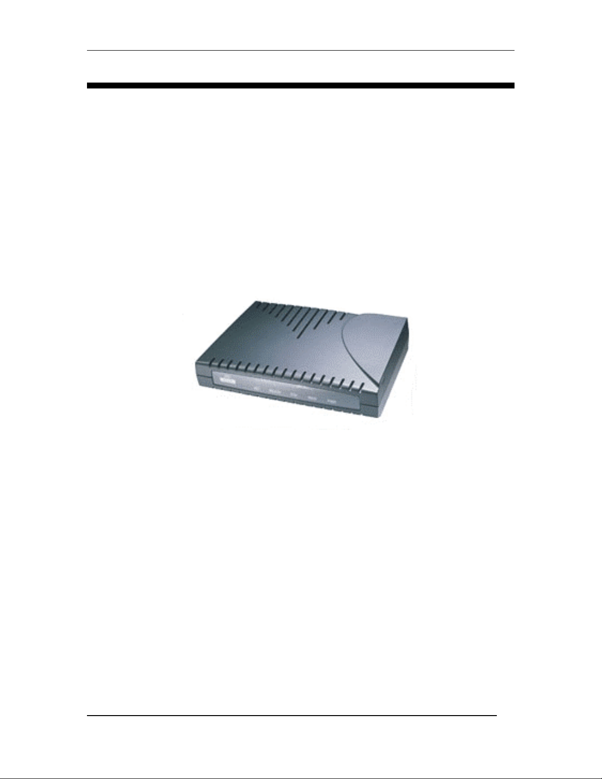
2. YOUR ANALOG TELEPHONE ADAPTOR (ATA) AT A GLANCE.................. 3
2.1 PORTS AND BUTTONS ................................................................................................. 3
2.2 LED DESCRIPTION ..................................................................................................... 3
3. INSTALLING YOUR ATA........................................................................................ 4
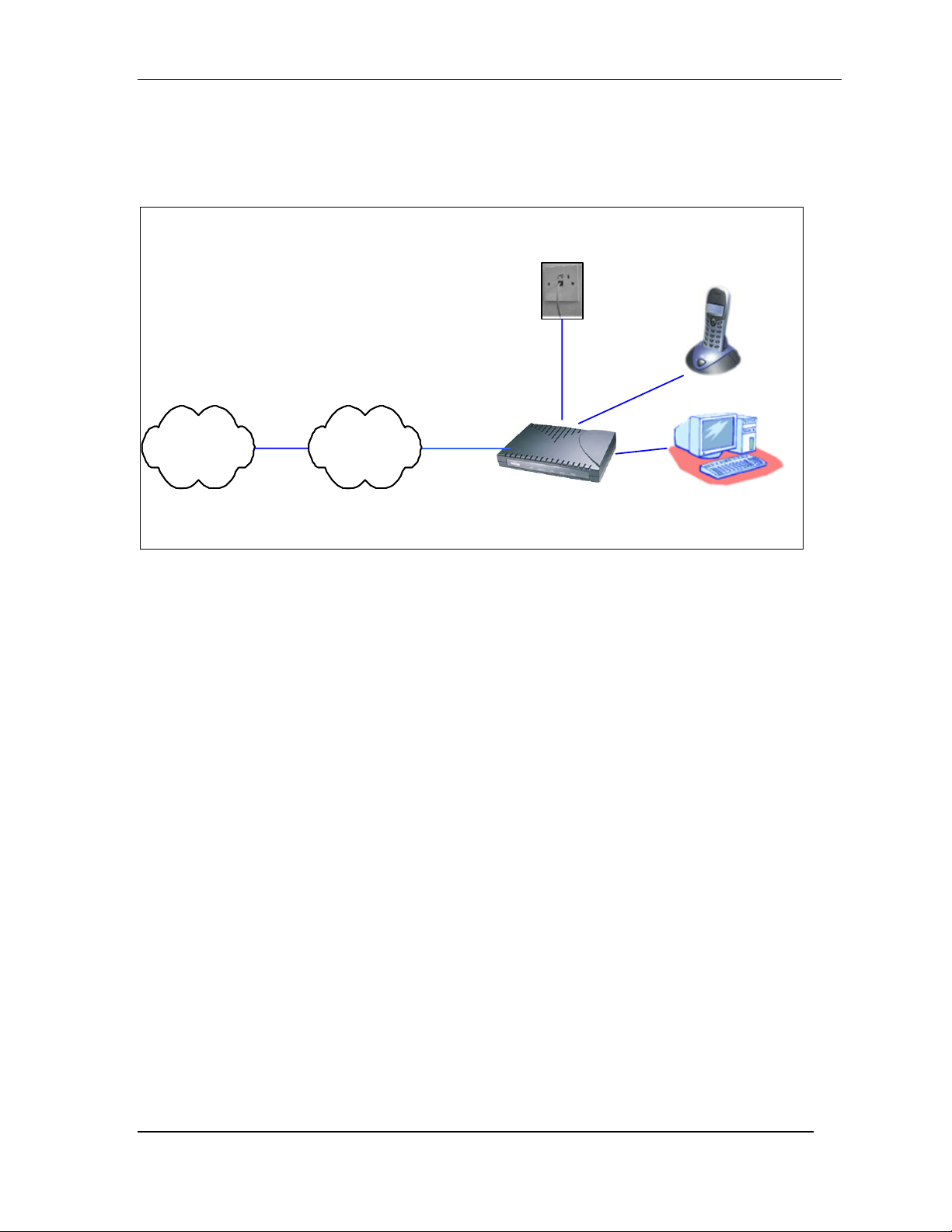
3.1 FOR SINGLE-USER CONNECTION .............................................................................. 4
3.2 FOR MULTIPLE-USERS CONNECTION........................................................................ 5
3.3 FOR COMPANY NETWORK CONNECTION.................................................................... 6
4. SETTING UP YOUR V300ATA ROUTER FUNCTIONALITY VIA GUI .......... 7
4.1 ACCESS TO V300ATA GUI....................................................................................... 7
4.2 SETUP MODE.............................................................................................................. 7
5BASIC MODE........................................................................................................... 8
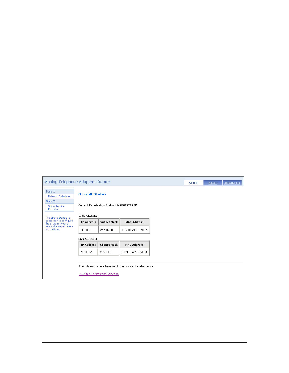
5.1 OVERALL STATUS.................................................................................................... 9
5.2 LAN STATUS......................................................................................................... 10
5.3 DHCP CLIENT STATUS.......................................................................................... 11
5.4 PPP STATUS .......................................................................................................... 12
5.5 TCP STATUS.......................................................................................................... 13
5.6 SYSTEM LOG.......................................................................................................... 14
6 BASIC CONFIGURATIONS................................................................................... 15
6.1 WAN CONFIGURATION.......................................................................................... 15
6.2 LAN & DHCP CONFIGURATION........................................................................... 18
6.3 NAT CONFIGURATION........................................................................................... 20
6.4 PORT FORWARDING CONFIGURATION.................................................................... 22
6.5 BRIDGE FILTERING................................................................................................ 23
6.6 DNS CONFIGURATION........................................................................................... 24
6.7 SAVE SETTINGS / REBOOT ..................................................................................... 25
7. ADVANCED MODE................................................................................................. 27
7.1 ATA CONFIGURATION............................................................................................. 27
7.2 SIP SERVICE PROVIDER CONFIGURATION................................................................ 28
7.2.1 SIP Service Provider........................................................................................ 28
7.3 ATA LOGIN ACCOUNT CONFIGURATION................................................................. 30
7.4 ATA TIMER CONFIGURATION.................................................................................. 32
7.5 COUNTRY SPECIFIC RING & TONES CONFIGURATION............................................ 33
7.6 ATA MISC CONFIGURATION ................................................................................. 35
8. ADMIN PRIVILEGE................................................................................................ 38

V300ATA VoIP User Manual
- iii -
8.1 ROUTE TABLE.......................................................................................................... 38
8.1.2 Route Configuration......................................................................................... 39
8.2 BRIDGE MAC TABLE............................................................................................... 40
8.3 RIP SYSTEM WIDE CONFIGURATION ....................................................................... 40
8.4 DMZ CONFIGURATION............................................................................................ 43
8.5 SNTP CONFIGURATION ........................................................................................... 44
8.6 MISCELLANEOUS CONFIGURATION.......................................................................... 45
8.7 ADMIN USERNAME / PASSWORD CONFIGURATION .................................................. 47
8.8 RESET TO DEFAULT ................................................................................................. 47
8.9 FIRMWARE UPDATE ................................................................................................. 48
8.10 SAVE / REBOOT...................................................................................................... 49

V300ATA VoIP User Manual
- 1 -
1. Introduction
Thank you on your purchase of the VoIP V300ATA
The V300ATA VoIP Analog Telephone Adaptor (ATA) products are standards-based
communication devices that deliver true, next-generation voice-over-IP (VoIP) terminations
to residences worldwide. Internet telephony employs a variety of protocols, including Real-
time Transport Protocol (RTP) for transport of multimedia data and Session Initiation
Protocol (SIP) for call signaling and control.
The V300ATA series are mixed-environment adaptors that interface legacy analog
telephones, fax machines, analog conference telephones and other analog devices to IP based
telephony networks thereby allowing users and ISPs to protect prior investments in analog
phones, fax machines, and speakerphones, and migrate to IP at their own pace. These
products address the needs of small-office environments, and the emerging VoIP voice
services whereby ISPs value add their ADSL or Cable Modem offering with VoIP services
by turning their analog devices into IP devices.
The V300ATA is installed at the subscriber's premises and supports one voice ports with a
POTS bypass for using the existing POTS primary line. The V300ATA supports 2
10/100BaseT Ethernet ports. This adaptor can make use of existing broadband pipes such as
digital subscriber line (DSL), fixed wireless and cable modem deployments. In addition, the
V300ATA has an internal Ethernet switch with routing capability, which allows for a direct
connection to another 10/100BASE-T Ethernet network via an RJ-45 interface, with single
LAN connectivity for both the V300ATA and a co-located PC or other Ethernet-based
device.
By turning any analog telephone into an IP telephone, the V300ATAs address the needs of
the emerging market of "second-line" residential voice-over-IP (VoIP) services. Broadband
service providers can now deploy voice services quickly to grow revenues and facilitate the
development of new services.

V300ATA VoIP User Manual
- 2 -
1.1 Main Features
• Call Out & Call In
• Voice over IP c all (through Gatekeeper)
• PSTN phone call (bypass I )
• IP address calling (Future Firmware Upgrade)
• Conference call (Ad Hoc Conference Call) (Up to Three Participants)
• Call features
• Call Waiting
• Call Hold
• Call Forward
• Call ID
• Setup & Configuration
• Auto (remote) Software Upgrade
• Web Based Configuration
• Password Protection for Web Configuration
• Audio Codec Feature
• Supports G.711, G.723,G.726,G.729a
• Voice Activity Detection
• Silence Compression
• Comfort Noise Generation
• Echo Cancellation
• Jitter Provisioning
• Protocols
• SIP (Default)
• T.38 Fax over IP support
• DHCP client
• DNS client
• Static IP
• FTP
• HTTP Server for Web Management (Firmware Upgrade)

V300ATA VoIP User Manual
- 3 -
2. Your Analog Telephone Adaptor (ATA) at a glance
The V300ATA may have different ports and LEDs. Let’s take a look at the different options.
Depending upon your model, it may have some or all of the features listed below
2.1 Ports and buttons
12V Power is where you connect the power. Make sure to observe the proper power
requirements. The require power is 12 volts.
Modem: 10/100 Base-T RJ-45 socket which is to be connected to your ADSL or Cable
modem.
Ethernet: 10/100 Base-T RJ-45 socket which is to be connected to your PC or to a
hub/switch if you want multiple PC access.
Reset and Restore to Factory Defaults:The restore to factory defaults feature will set the
V300ATA to its factory default configuration by resetting the V300ATA. You may need to
place the V300ATA into its factory defaults if the configuration is changed, you will lose the
ability to interface to the V300ATA via the web interface, or following a software upgrade,.
To reset the V300ATA, simply press the reset button for about ~ 8 seconds. The V300ATA
will be reset to its factory defaults and after about 30 ~ 40 seconds the V300ATA will
become operational again.
Phone: RJ-11 telephone socket, which is to be connected to an PSTN analog phone.
Line: RJ-11 telephone socket, which is to be connected to telephone wall socket. In by-pass
mode, the PSTN signal will be send to the analog phone
2.2 LED description
IN USE: Lights up when the device is powered up and the telephone handset is off-hook
READY: Lights up when VoIP service is in operational mode.
ETH: Lights up when Ethernet link is detected and blinks according to LAN Ethernet traffic.
WAN: Lights up when WAN link is detected and blinks according to WAN traffic.
PWR: Lights up when device is power on.

V300ATA VoIP User Manual
- 4 -
3. Installing your ATA
3.1 For Single-User Connection
The following shows a typical single-user connection. You need to have a ADSL modem or
Cable modem before you can connect to the ATA. It can be placed behind router or straight
from the moem. Check if your Computer/Notebook has an Ethernet Port. The Telephone set
is connected to the RJ-11
3.1.1 ADSL Connection
www
ADSL
Modem / Router
Computer/Network with
Ethernet NetworkCard
Telephone Set
internet V300ATATelephone
WallSocket
POTSSplitter
Figure 3-1: Connection via ADSL for single User
3.1.2 Cable Connection
www
Cable
Modem Computer/Network with
Ethernet NetworkCard
Telephone Set
internet
Telephone
WallSocket
Cable
Point
Cable/DSL
Router V300ATA
Figure 3-2: Connection via Cable for single User

V300ATA VoIP User Manual
- 5 -
3.2 For Multiple-Users Connection
If you want to connect more than a one Computers/Notebooks connection, you may connect
the ATA to a switch/hub; the switch/hub will then be connected to the other
Computers/Notebook. The diagram below shows multiple-users connection using ADSL.
Cable users connection is similar to the ADSL, by using an Ethernet (RJ-45) cable, connect it
from V300ATA to a Hub/Switch.
Hub/Switch
www
Computer/
Network with
EthernetNetwork
Card
Telephone Set
internet Telephone
WallSocket
POTSSplitter
Computer/
Network with
EthernetNetwork
Card
ADSL
Modem / Router
V300ATA
Figure 3-3: Connection via ADSL /Cable or multiple users
For details on the connection and types of Ethernet Network cable to use with the Ethernet
Hub/Switch, please refer to the user guide that comes with your Ethernet Hub/Switch.

V300ATA VoIP User Manual
- 6 -
3.3 For Company Network Connection
Please seek advise from your company’s Network Administrator, to open ports 5000,5060
for the VoIP functions.
www
Computer/Network with
Ethernet NetworkCard
Telephone Set
internet
Telephone
WallSocket
Company
Network
Figure 3-4: Connection via Company Network

V300ATA VoIP User Manual
- 7 -
4. Setting up your V300ATA router functionality via GUI
4.1 Access to V300ATA GUI.
To configure your V300ATA, you need to login to the device using a web browser.
i) Connect the V300ATA as shown in the Section 3.
ii) Launch your web browser.
iii) Type in 10.0.0.99 at the Address bar and press Enter key.
(Note: 10.0.0.99 is the default IP address for Router).
4.2 Setup Mode.
Upon successfully logging in, the Setup mode screen as shown below is displayed.
Note :
Please refer the Easy Start Manual, ”Step 5 VoIP Configuration Setup” for the details
Figure 4.1: Setup Page

V300ATA VoIP User Manual
- 8 -
5 Basic Mode
It provides a brief outline of the router function of individual hyper links on the left menu.
Figure: 5-0: Basic Mode Description

V300ATA VoIP User Manual
- 9 -
5.1 Overall Status
It summaries all the information regarding the WAN and LAN of the V300ATA
Firmware Version: This section displays the current version of ATA Firmware.
WAN Connection Type: It shows the type of connection that is currently used. It will show
Connected when it get connected to ISP.
WAN Statistic: This shows the WAN interface IP address assigned to your router.
LAN Statistic: This shows the number of computers connected to the router. It also shows
the LAN interface IP addresses assigned to the computers.
Figure: 5-1: Overall Status

V300ATA VoIP User Manual
- 10 -
5.2 LAN Status
It fields display the IP address, Subnet Mask and MAC address for the LAN interface.
Figure: 5-2: LAN Status
Total Number of LAN Interfaces: This field displays the total number of available
interfaces for the LAN interface. The total number of available interfaces is the amount of
computers that are able to hook up to the DHCP Server.
Number of Ethernet Devices Connected to the DHCP Server: These fields display the
DHCP client table with the assigned IP addresses and MAC addresses.
Note: If there are no devices connected to the DHCP server, then a table will not appear,
otherwise a table (Table Headings: IP Address, MAC Address) listing all devices connected
to DHCP server will appear on the bottom of the page.

V300ATA VoIP User Manual
- 11 -
5.3 DHCP Client Status
This page displays the WAN IP address which is assigned by the ISP.
• Select Release or Renew in the list box
• Press Execute to Renew or Release the WAN connection.
Figure: 5-3: DHCP Client Status

V300ATA VoIP User Manual
- 12 -
5.4 PPP Status
This page displays the status of each PPP session for each PPP interface. This page contains
information that is dynamic and will refresh every 8 seconds.
To Connect/Disconnect PPP connection:
1. Type the connection number you want to Connect/Disconnect in the text field
2. Select Connect or Disconnect in the list box
3. Press Execute to Connect or Disconnect the selected PPP connection.
(Note: For cable modem users, you are not able to connect using this option.)
Figure: 5-4: PPP Status
PPP (Point-to-Point Protocol): The table displays the following fields:
• Connection Name: This is user defined. User defined connections for PPP can be
created in PPP Configuration page.
• Interface: States the interface that is being used (PVC0 ... PVC7).
• Mode: There are two available modes for the connection:
PPP over Ethernet (PPPoE)
• Status: States whether PPP connection is Connected or Not Connected.
• Packets Sent: Number of packets sent by a particular PPP Connection.
• Packets Received: Number of packets received by a particular PPP Connection.
• Bytes Sent: Number of bytes sent by a particular PPP Connection.
• Bytes Received: Number bytes received by a particular PPP Connection.
Connect and Disconnect: This field allows you to manually connect/disconnect the PPP
connection for each PPP interface. In other words, each PPP session can be connected and
disconnected individually.
• Connection #: Specifies the PPP session to be connected/disconnected.

V300ATA VoIP User Manual
- 13 -
• Connect/Disconnect Execute: Press this button to either connect or disconnect.
Connection status dialog will be displayed below the Execute button after it is pressed.
Sample dialog with explanation:
• PPP X: Connecting... This is displayed while the PPP session is attempting connect
to the ISP.
• PPP X: Connect ERROR This is displayed when a connection cannot be made due
to an error.
• PPP X: is currently not connected This is displayed when a disconnect attempt is
made on a session that is not currently connected.
• PPP X: does not exist! This is displayed when a connect or disconnect attempt is
made on a session number that does not exist.
5.5 TCP Status
This page displays all the relevant TCP packets and data information. You can reset the
counters to clear all the attributes.
Figure: 5-5: TCP Status
Reset Counters: This button allows user to reset the TCP Status counter.
General: Total Packets, Data Packets, Data Bytes, Out of Order Packets, Out of Order Bytes
Discarded Packets: Bad Checksum, Bad Offset Header, Too Short
Connections: Initiated, Accepted, Established, Closed.

V300ATA VoIP User Manual
- 14 -
5.6 System Log
The System Log page shows the events triggered by the system.
This page contains information that is dynamic and will refresh every 5 seconds.
Figure: 5-6: System Log
Clear Log: This field allows you to clear the current contents of the System Log.
Save Log: This field allows you to save the current contents of the System Log by right click
HERE and select “Save Target As” to save it into a text file.

V300ATA VoIP User Manual
- 15 -
6 Basic Configurations
6.1 WAN Configuration
This page let you configure the WAN settings.
Figure 6-1 WAN Configuration
Bridge: Enable to connect the LAN to the WAN (bridge the two connections). This is
available in Bridge Mode only. Default is Disabled.
IGMP: IGMP (Internet Group Management Protocol) relay/proxy specification and
environment, default is Disabled. IGMP is available in all modes and all encapsulations.
Support IGMP proxy/relay function for ADSL Bridge/Router, based on the following
requirement and cases:
• On CO side, there must be at least one IGMP querier (router) present. IGMP querier
will send IGMP query packet. The ADSL Bridge/Router is responsible to relay these
IGMP queries to Ethernet.
• End-user multicast application device sends IGMP report while receiving IGMP
query or being activated by the user. The ADSL Bridge/Router should be responsible
to proxy (that is, change source IP to ADSL Bridge/Router’s WAN IP) the IGMP
report to ADSL WAN side, including all PVCs. The same case is for IGMP leave
packet.
• Not necessary to relay multicast routing between two ADSL PVCs or two interfaces
in LAN side.

V300ATA VoIP User Manual
- 16 -
• Special purpose multicast packet (such as RIP 2 packet) should run without
Interference.
Static IP Settings are for users who have a Static IP Address (WAN side) from their ISP.
IP Address: This is the static IP Address given by the ISP.
Range for IP Address is x.x.x.y, where 0 ≤x≤255 and 1 ≤y≤254, default is
192.168.241.101.
Subnet Mask: This is the subnet mask given by the ISP.
Range for Subnet Mask is x.x.x.x, where 0 ≤x≤255, default is 255.255.255.0
Gateway: This is the Gateway given by the ISP.
Range for Gateway is x.x.x.y, where 0 ≤x≤255 and 1 ≤y≤254, default is 0.0.0.0.
Gateway: This is the Gateway IP address provided by your ISP
DHCP Client: This is to enable or disable (default) the ADSL Bridge/Router WAN as a
DHCP client, where the ISP would be the DHCP server. DHCP Client is generally used in
the following encapsulations: 1483 Bridged IP LLC, 1483 Routed IP LLC, 1483 Bridged IP
VC-MUX, 1483 Routed IP VC-Mux, and Classical IP over ATM. This option is for non-
static (dynamic) IP addresses.
Host Name: When DHCP Client is Enabled, copy the ISP recognized Host Name here.
The Host Name can be up to 19 characters.
MAC Spoofing: Enable MAC Spoofing to make a different MAC Address appear on the
WAN side. This is also used to solve the scenario where the ISP only recognizes one MAC
Address.
Default is Disabled.
MAC Address: When MAC Spoofing is enabled, copy the ISP-recognized MAC address
here. Format for MAC address is six pairs of hexadecimal numbers (0-9, A-F) separated by
colons.
Default is 00:00:00:00:00:00.
PPP: Default is unchecking, check to enable.
User Name: Enter the PPP user name (provided by the ISP). The User Name can be up to
127 characters.
Password: Enter the PPP password (provided by the ISP). The Password is not needed to
delete or modify the account. The Password can be up to 127 characters.
PPP Account Configuration Status table will be displayed at the bottom of this page to
show all the accounts (Table headings: Account Name and User Name). The status table does
not display the password.

V300ATA VoIP User Manual
- 17 -
MRU: The MRU (Maximum Receive Unit) field indicates the maximum size IP packet that
the peer of PPP connection (this device) can receive. During the PPP negotiation, the peer of
the PPP connection will indicate its MRU and will accept any value up to that size. The
actual MTU of the PPP connection will be set to the smaller of the two (MTU and the peer’s
MRU). In the normal negotiation, the peer will accept this MRU and will not send packet
with information field larger than this value.
Range for MRU field is 0-32767, default value is 1492.
MTU: Maximum Transmission Unit (MTU) is the largest size packet that can be sent by the
modem. If the network stack of any packet is larger than the MTU value, then the packet will
be fragmented before the transmission. During the PPP negotiation, the peer of the PPP
connection will indicate its MRU and will accept any value up to that size.
The actual MTU of the PPP connection will be set to the smaller of the two (MTU and the
peer’s MRU).
Range for MTU field is 0-32767, default value is 1492.
MSS: Maximum Segment Size is the largest size of data that TCP will send in a single,
unfragmented IP packet. The LAN client and the WAN host will indicate their MSS during
the TCP connection handshake.
Range for MSS field is 0-32767, default value is 1432.
Authentication: The different types of available authentications are:
• Auto: When auto is selected, PAP mode will run by default. However, if PAP fails,
then CHAP will run as the secondary protocol. This is the default setting.
• PAP: Password Authentication Procedure. Authentication is done through username
and password.
• CHAP: Challenge-Handshake Authentication Protocol. Typically more secure than
PAP, CHAP uses username and password in combination with a randomly generated
challenge
Ensure to click Submit and Save Settings for your configuration to take effect.
Table of contents