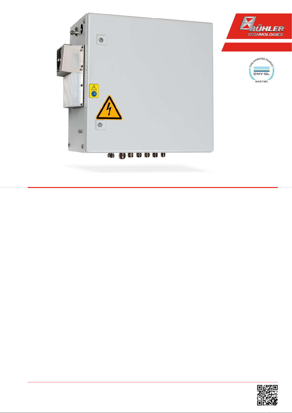
Bühler technologies CU-EMA+ Owner's manual

Gas Analysis
Installation and Operation Instructions
Original instructions
Cooling unit
CU-EMA+
BE440029
10/2020
Bühler Technologies GmbH, Harkortstr. 29, D-40880 Ratingen
Tel. +49 (0) 21 02 / 49 89-0, Fax: +49 (0) 21 02 / 49 89-20
E-Mail: [email protected]
Internet: www.buehler-technologies.com

Bühler Technologies GmbH, Harkortstr. 29, D-40880 Ratingen
Tel. +49 (0) 21 02 / 49 89-0, Fax: +49 (0) 21 02 / 49 89-20
Internet: www.buehler-technologies.com
E-Mail: [email protected]
Read this instruction carefully prior to installation and/or use. Pay at-
tention particularly to all advises and safety instructions to prevent in-
juries. Bühler Technologies can not be held responsible for misusing
the product or unreliable function due to unauthorised modifications.
All rights reserved. Bühler Technologies GmbH 2020
Document information
Document No......................................................... BE440029
Version.........................................................................10/2020

CU-EMA+
Contents
1 Introduction..................................................................................................................................................................................................................... 2
1.1 Intended use .........................................................................................................................................................................................................2
1.2 Overview ................................................................................................................................................................................................................2
1.3 Scope of delivery.................................................................................................................................................................................................. 2
1.4 Ordering instructions ........................................................................................................................................................................................ 3
1.4.1 Cooler with Two In-Line Heat Exchangers.....................................................................................................................................3
2 Safety instructions.........................................................................................................................................................................................................4
2.1 Important advice.................................................................................................................................................................................................4
2.2 General hazard warnings ................................................................................................................................................................................. 5
3 Transport and storage ..................................................................................................................................................................................................6
4 Installation and connection ........................................................................................................................................................................................ 7
4.1 Installation site requirements......................................................................................................................................................................... 7
4.2 Installation ............................................................................................................................................................................................................ 7
4.3 Electrical connections ........................................................................................................................................................................................8
4.3.1 Connection ............................................................................................................................................................................................ 9
4.4 Gas Connections ..................................................................................................................................................................................................9
5 Operation and control ................................................................................................................................................................................................. 11
5.1 Description of functions................................................................................................................................................................................... 11
5.2 Use of menu functions .................................................................................................................................................................................... 12
5.2.1 Lock Menu.............................................................................................................................................................................................12
5.2.2 Menu navigation overview.............................................................................................................................................................. 13
5.3 Description of menu functions ......................................................................................................................................................................15
5.3.1 Main menu........................................................................................................................................................................................... 15
5.3.2 Submenu 1 ............................................................................................................................................................................................16
5.3.3 Submenu 1 (global settings)............................................................................................................................................................ 17
5.3.4 Set favourite menu ............................................................................................................................................................................19
5.3.5 Description of Other Options..........................................................................................................................................................19
6 Maintenance..................................................................................................................................................................................................................20
6.1 Maintenance Intervals..................................................................................................................................................................................... 21
6.2 Cleaning ............................................................................................................................................................................................................... 21
7 Service and repair.........................................................................................................................................................................................................22
7.1 Troubleshooting ................................................................................................................................................................................................22
7.1.1 Error messages on the display........................................................................................................................................................23
7.2 Safety instructions............................................................................................................................................................................................24
7.3 Replacing the hose of the peristaltic pump...............................................................................................................................................25
7.4 Cleaning and Calibrating the Moisture Detector ....................................................................................................................................25
7.5 Cleaning and removal of the heat exchanger...........................................................................................................................................25
7.6 Replacing the Microfuse for the Expansion Module/Regulator..........................................................................................................26
7.7 Replacing the Solenoid Valve.........................................................................................................................................................................27
7.8 Replacing the Relays.........................................................................................................................................................................................27
7.9 Spare parts and accessories ...........................................................................................................................................................................27
7.9.1 Spare parts and accessories.............................................................................................................................................................27
8 Disposal...........................................................................................................................................................................................................................28
9 Appendices.....................................................................................................................................................................................................................29
9.1 Flow Diagram .....................................................................................................................................................................................................29
9.2 Technical Data....................................................................................................................................................................................................30
9.3 Technical Data - Options.................................................................................................................................................................................30
9.4 Outlet.....................................................................................................................................................................................................................31
9.4.1 Heat exchanger description ............................................................................................................................................................ 31
9.4.2 Heat exchanger overview................................................................................................................................................................. 31
9.5 Dimensions .........................................................................................................................................................................................................32
10 Attached documents................................................................................................................................................................................................... 33
iBühler Technologies GmbHBE440029 ◦ 10/2020

CU-EMA+
1 Introduction
1.1 Intended use
This device is an essential component for conditioning the sample gas to protect the downstream analysis instrument from re-
sidual moisture in the sample gas.
Please note the specifications in the data sheet on the specific intended use, existing material combinations, as well as pressure
and temperature limits.
1.2 Overview
The CU-EMA+ cooler was designed specifically for the requirements of gas conditioning for continuously measuring emissions
in maritime applications. Dividing the unit into an internal and external section achieves the IP rating required under the stand-
ard without requiring venting the interior. The series connection of the heat exchangers will cool in two cycles to minimise wash
out effects.
The exact item number of the model defined by you is determined by the model code in the category ordering information.
The gas cooler comes standard with peristaltic pump and moisture detector. Additional components which every conditioning
system should feature can optionally be connected:
– Connection for adding instrument air to purge the system,
– Solenoid valve for adding test gas,
– Heated line connection and regulation,
– metric/US style external connections.
Here the approach is to simplify creating a complete system in a cost-efficient way through pre-installed components with
hoses connected. We further paid attention to easy access to wear parts and consumables.
1.3 Scope of delivery
– Cooler unit
– Product documentation
– Heated line (optional)
2 Bühler Technologies GmbH BE440029 ◦ 10/2020

CU-EMA+
1.4 Ordering instructions
1.4.1 Cooler with Two In-Line Heat Exchangers
The item number is a code for the configuration of your unit. Please use the following model code:
4496 2 8 2 2 0 X 1 X X 2 0 0 X 0 0 X X X Product Characteristics
Cooler (with 2 in-line heat exchangers)
2 CU-EMA+: Ambient temperature 50 °C
Certifications
0 Standard applications – CE
Supply voltage
1 115 VAC, 50/60 Hz
2 230 VAC, 50/60 Hz
Heat exchanger
1 2 2 Glass, 2 x MTG-2, metric
1 2 7 Glass, 2 x MTG-2-I, US
1 3 2 PVDF, 2 x MTV-2, metric
1 3 7 PVDF, 2 x MTV-2-I, US
Peristaltic Pumps
2 0 CPdouble with hose nipple, angled
Moisture detector
0 0 0 0 without moisture detector
0 1 0 0 1 moisture detector with adapter
Options
0 0 Without option
0 1 Instrument air purging connection
1 0 Solenoid valve for test gas
1 1 Instrument air purging connection and solenoid valve for test gas
Heated line
0 no heated line
1 ready for self-regulating heated line
2 -
3 -
4 -
5 ready for regulated heated line
65 m regulated heated line *
78 m regulated heated line *
810 m regulated heated line
915 m regulated heated line
*for 115 VAC only these lengths available
3Bühler Technologies GmbHBE440029 ◦ 10/2020

CU-EMA+
2 Safety instructions
2.1 Important advice
Operation of the device is only valid if:
– the product is used under the conditions described in the installation- and operation instruction, the intended application
according to the type plate and the intended use. In case of unauthorized modifications done by the user Bühler Technolo-
gies GmbH can not be held responsible for any damage,
– when complying with the specifications and markings on the nameplates.
– the performance limits given in the datasheets and in the installation- and operation instruction are obeyed,
– monitoring devices and safety devices are installed properly,
– service and repair is carried out by Bühler Technologies GmbH,
– only original spare parts are used.
This manual is part of the equipment. The manufacturer keeps the right to modify specifications without advanced notice. Keep
this manual for later use.
Any unauthorised changes or modifications will void the EU declaration of conformity and approvals of the system.
Signal words for warnings
DANGER
Signal word for an imminent danger with high risk, resulting in severe injuries or death if not avoided.
WARNING
Signal word for a hazardous situation with medium risk, possibly resulting in severe injuries or death if not
avoided.
CAUTION
Signal word for a hazardous situation with low risk, resulting in damaged to the device or the property or
minor or medium injuries if not avoided.
NOTICE
Signal word for important information to the product.
Warning signs
In this manual, the following warning signs are used:
Warning against hazardous situations General notice
Warning against electrical voltage Disconnect from mains
Warning against respiration of toxic gases Wear respirator
Warning against acid and corrosive substances Wear eye/face protection
Warning against potentially explosive atmospheres Wear protection gloves
Warning against hot surface
4 Bühler Technologies GmbH BE440029 ◦ 10/2020

CU-EMA+
2.2 General hazard warnings
The equipment must be installed by a professional familiar with the safety requirements and risks.
Be sure to observe the safety regulations and generally applicable rules of technology relevant for the installation site. Prevent
malfunctions and avoid personal injuries and property damage.
The operator of the system must ensure:
– Safety notices and operating instructions are available and observed,
– The respective national accident prevention regulations are observed,
– The permissible data and operational conditions are maintained,
– Safety guards are used and mandatory maintenance is performed,
– Legal regulations are observed during disposal,
– compliance with national installation regulations.
Maintenance, Repair
Please note during maintenance and repairs:
– Repairs to the unit must be performed by Bühler authorised personnel.
– Only perform conversion-, maintenance or installation work described in these operating and installation instructions.
– Always use genuine spare parts.
– Do not install damaged or defective spare part. If necessary, visually inspect prior to installation to determine any obvious
damage to the spare parts.
Always observe the applicable safety and operating regulations in the respective country of use when performing any type of
maintenance.
DANGER Electric voltage
Risk of electric shock
a) Always disconnect the unit from the mains before working on it. After shutting off
the power, allow a discharge time of at least 5seconds.
b) Secure the device from accidental restarting.
c) The unit may only be opened by trained, competent personnel.
d) Ensure the correct voltages supply.
DANGER Toxic, corrosive gas/condensate
Sample gas/condensate may be hazardous to health.
a) Purge the device with inert gas or air (only when non-flammable gases inside the gas
path) for some time before connecting the lines or performing maintenance.
b) If necessary, ensure a safe gas/condensate discharge.
c) Check the lines in and on the device for leaks.
d) Always disconnect the gas supply when performing maintenance or repairs.
e) Protect yourself from toxic/corrosive gasses/condensate when performing mainten-
ance. Wear suitable protective equipment.
DANGER Potentially explosive atmosphere
Explosion hazard if used in hazardous areas.
The device is not suitable for operation in hazardous areas with potentially explosive at-
mospheres.
Do not expose the device to combustible or explosive gas mixtures.
CAUTION Hot surface
Burning hazard
Let the device cool down before maintaining.
5Bühler Technologies GmbHBE440029 ◦ 10/2020

CU-EMA+
3 Transport and storage
Only transport the product inside the original packaging or a suitable alternative.
The equipment must be protected from moisture and heat when not in use. They must be stored in a covered, dry and dust-free
room at a temperature between -20°C to 40°C (-4°F to 104°F).
CAUTION Health hazard/tipping hazard
Transport and carry the products in a way which is not damaging to health.
a) If necessary, use aids to facilitate transport and installation.
b) Avoid damage to the product. Handle the product with care.
c) Avoid sudden acceleration.
d) Do not turn the device upside down or stack other items on top of it.
e) Please note the warnings on the packaging (such as "This Side Up", "Fragile", etc.).
6 Bühler Technologies GmbH BE440029 ◦ 10/2020

CU-EMA+
4 Installation and connection
4.1 Installation site requirements
The following requirements must be met during installation:
– Never install the device near sources of heat or vibration, in direct sunlight, or near high frequencies or magnetic fields. The
operator must install a lightning arrester and overvoltage protection.
– Consider the electromagnetic compatibility of nearby equipment when selecting the installation site.
– To maintain electrical safety, never operate the device in atmospheres with an oxygen content above 21 %.
– The device must be anchored to the wall, which must be able to support the weight.
– Please refer to chapter Appendix/Technical Data for the max. ambient temperature. Operation outside the limits will void
the warranty for this device.
– Do not obstruct the convection of the device. Leave adequate space between the vents and the nearest object. The clearance
must especially be a minimum of 10 cm on the air outlet side. The air intake and outlet must be clear. Heat may otherwise
build up.
– Protect from shock and impact.
– Never expose the display components to external forces.
– Never install the device outdoors.
DANGER Potentially explosive atmosphere
Explosion hazard if used in hazardous areas.
The device is not suitable for operation in hazardous areas with potentially explosive at-
mospheres.
Do not expose the device to combustible or explosive gas mixtures.
4.2 Installation
Install the device in the specified position, see chapter Dimensions [> page32].
CAUTION Damage/installation
Avoid damage to the product. Handle the product with care.
If wall brackets are required for installing the device, ensure these meet DIN EN 61010-1.
NOTICE Please note:
At the time of delivery, the device has a leak rate of less than 1.5mbar/h at a test pres-
sure of 160mbar and an ambient temperature of 20°C.
Check the system for leaks following transport and installation before starting it. The op-
erator must include this in his risk/safety assessment and if necessary take additional
measures to prevent explosion and/or health hazards.
When changing the factory settings, please document the factory presets as well as the
changed values.
7Bühler Technologies GmbHBE440029 ◦ 10/2020

CU-EMA+
4.3 Electrical connections
All connection lines can be fed into the device through the cable glands at the bottom.
Include strain relief for the connection cables. The supply line cross-sections must be suitable for the rated current and meet
local regulations.
The signal and supply lines of the device must be properly connected.
Please note the clamping points of the following cable glands:
Thread Clamping range
M25 11.0mm – 17.0mm
M20 6.0mm – 12.0mm
Run the lines so the insulation will not be damaged. If necessary, secure the lines with suitable means and avoid excess line
lengths.
The power supply must be connected as per chapter Connection [> page9] or per the wiring diagrams.
The power and voltage supply for the components may require the following separators:
RCD, main switch and circuit breaker or fuses
If applicable, the following requirements must be met for operation:
– The RCD must shut off the load within the prescribed period (200 ms at 115 VAC, 40 ms at 230 VAC). It must be suitable for the
maximum load.
– The main switch must be installed near the device, easy to access and marked as a separator.
– The circuit breaker/fuses protect all supply lines but not the earth conductor.
The fuses should be arranged side by side, have the same rating/characteristic, and not be connected to the neutral wire of
multi-phase equipment.
Please refer to chapter Technical Data [> page30] for the applicable separator data.
DANGER Electric voltage
Risk of electric shock
a) Always disconnect the unit from the mains before working on it. After shutting off
the power, allow a discharge time of at least 5seconds.
b) Secure the device from accidental restarting.
c) The unit may only be opened by trained, competent personnel.
d) Ensure the correct voltages supply.
DANGER Potential equalisation
Connect the system’s potential equalisation to the potential equalisation on site. Stray
electric currents may not flow through this connection.
WARNING Hazardous electrical voltage
The device must be installed by trained staff only.
WARNING Electric voltage
Insulation test will damage the device
Do not test the electric strength if the entire unit is under high voltage!
CAUTION Wrong mains voltage
Wrong mains voltage may damage the device.
Regard the correct mains voltage as given on the type plate.
8 Bühler Technologies GmbH BE440029 ◦ 10/2020

CU-EMA+
CAUTION Supply cable
The power adapter must be suitable for the maximum power used by the device.
It must be heat-resistant and must not come into contact with hot surfaces. The power
supply must meet IEC60227 or IEC60245. Or be approved by another recognised testing
body.
NOTICE Please note:
The structure and quality of the electrical installation can have a considerable impact on
the reliability and performance of the devices. We therefore strongly recommend the
personnel responsible for the electrical installation familiarise themselves with the in-
cluded circuit diagrams and instructions before planning the installation. Please observe
the local laws. The device must be connected by a trained professional. Please also note
the operation instructions for the individual devices.
4.3.1 Connection
Type Voltage Terminals Function
Power supply 115VAC/230VAC, 50 Hz/60Hz X0: 1 + 2 + PE Input for entire device
Power supply 115VAC/230VAC, 50Hz/60Hz
max. 800 VA
X1: 3+ 8 + PE Output for external consumers
Input contact max. 115VAC/230VAC, 24 VDC
2 A, 50 VA (or less depending on consumer)
X3: 1 + 3 + PE Input external consumers
(looped through to X4: 2)
Output contacts max. 115VAC/230VAC, 24 VDC
2 A, 50 VA
X4: 1 + 2 External consumer
X4: 1 + 3 Sample gas cooler status, moisture and
operational regulated heated line
Options
Type Voltage Terminals Function
Power supply 115VAC/230VAC, 50Hz/60Hz
max. 1600 VA
X2: 1 + 2 + PE Output regulated heated line
Power supply 115VAC/230VAC, 50Hz/60Hz
max. 1600 VA
X2.1 1 + 2 + PE Output self-regulating heated line
Inputs
(customer mains)
24 VDC/18 mA X4: 4 + 5 Control for optional test gas solenoid valve
115VAC/230VAC/6 mA X4: 6 + 7
Input PT100 --- X5: 1 + 2 Input regulated heated line
4.4 Gas Connections
Please refer to the assembly plan in chapter Dimensions [> page32] for the number and positions of gas connections
The heated sample gas line must have a downward slant toward the gas inlet.
After connecting the sample gas line it must be braced and secured with the clamp. Longer sample gas lines may require addi-
tional clamps along the device path.
DANGER Toxic, corrosive gases, sample gas can be harmful.
Sample gas/condensate may be hazardous to health.
a) Purge the device with inert gas or air (only when non-flammable gases inside the gas
path) for some time before connecting the lines or performing maintenance.
b) If necessary, ensure safe gas discharge.
c) Switch off the gas supply before performing maintenance and protect from opening
inadvertently.
d) Wear suitable protective equipment when performing maintenance to protect your-
self from toxic/corrosive gases/mediums.
e) Also protect yourself with a suitable gas sensor when asphyxiant gases such as N2 oc-
cur in the gas path.
9Bühler Technologies GmbHBE440029 ◦ 10/2020

CU-EMA+
DANGER High pressure, danger due to gases being discharged at high pressure!
a) Disconnect the device from the system pneumatics.
b) Release pressure from the lines before beginning work.
c) Secure the equipment from accidentally being reconnected to the pneumatic supply
DANGER Sample gas can be harmful.
Always install the sample gas outlet in a location where persons will not be harmed. En-
sure the lines and connections are leak-proof.
DANGER Gas emanation
Danger to life due to gas leaks if used incorrectly.
a) Always use the device as specified in this manual. Observe the process conditions.
b) Gas connections must be connected with suitable connectors and be connected cor-
rectly.
c) The gas connection must be checked for leaks. Secure the lines adequately.
10 Bühler Technologies GmbH BE440029 ◦ 10/2020

CU-EMA+
5 Operation and control
NOTICE
Only operate the device with the door closed and within the specifications!
After starting the device via circuit breaker FC43, the display of the sample gas cooler will show the software version, then the
block temperature. The display S2 will stay on until the block temperature has reached the preset value (± adjustable alarm
range). The status contact is in the Alarm position.
Once the target temperature range has been reached and the moisture detector does not report an error, the temperature will
continuously be displayed and the status contact switches over. With the optional regulated heated line, the temperature signal
will also be sent to the status contact.
If the display flashes during operation or an error message appears, please refer to item "Troubleshooting”.
Please refer to the data sheet for performance data and maximum ratings.
5.1 Description of functions
The sample gas cooler is controlled by a microprocessor.
The programmable display shows the block temperature in the selected display unit (°C/°F) (factory preset °C). Application-spe-
cific settings can easily be configured guided by the menu, using the 5 buttons. For one, this applies to the target outlet dew
point, which can be set from 2 to 20°C (36 to 68°F) (factory setting 5°C/41°F).
And then the warning thresholds can be adjusted for low and excess temperature. These are set relative to the outlet dew point
τa setting. For the low temperature the range is τa -1 to - 3K (at a minimum 1°C cooling block temperature), for the excess tem-
perature the range is τa +1 to +7K. The factory settings for both values are 3K.
The flashing and an LED on the display unit plus the potential-free contact indicate the warning range has been overrun or un-
derrun (e.g. after switching on) plus the potential-free contact.
11Bühler Technologies GmbHBE440029 ◦ 10/2020

CU-EMA+
5.2 Use of menu functions
Brief description of the operating principle:
The unit is operated using 5 keys. Their functions are:
Button Section Functions
or
OK
Display – Switches from the measurement display to the main menu
Menu – Selects the menu item displayed
Enter – Applies an edited value or a selection
Display – temporarily switches to the alternative measurement display (if option installed)
Menu – Back
Enter – Increase value or browse selection
– Note:
– Press button 1 x = changes parameter / value by one;
– Hold button = fast mode (numerical values only)
– Display flashes: modified parameter/value
– Steady display: original display/value
Display – temporarily switches to the alternative measurement display (if option installed)
Menu – Next
Enter – Reduce value or browse selection
ESC
Menu – Move one level up
Enter – Return to menu
Changes will not be saved!
F
or
Func
– Sets a menu to favourite.
(Note: The favourite menu will also be activated with the menu locked!)
5.2.1 Lock Menu
Some menus can be locked to prevent inadvertently changing the settings of the unit. This requires setting a code. For informa-
tion on setting up or disabling the menu lock please refer to "Global Settings" (toP) under menu item toP>Loc.
The menu lock is not enabled at the time of delivery, all menu items can be accessed.
With the menu locked, only the following menu items will be visible without entering the correct code:
Menu item Explanation
toP > unit Temperature unit selection (°C or °F).
F or Func. Accessing the Favourites menu
NOTICE!This menu may be one that is normally locked.
12 Bühler Technologies GmbH BE440029 ◦ 10/2020

CU-EMA+
5.2.2 Menu navigation overview
When pressing the OK button in normal mode, the display will show the prompt code if the menu is locked. Use the ▲ and ▼
buttons to enter the correct code and press OK.
If an incorrect code or no code is entered, the menu will not be unlocked and you will not be able to access all menu items.
If you forgot the password you can always enter master code 287 to access the menu; the menu will be unlocked.
The following image shows an overview of the menu structure.
Items with a dashed frame will only appear with the respective settings or with the respective status messages.
The factory settings and ranges are specified in the overview as well as under the respective menu item. The factory settings ap-
ply unless otherwise agreed.
You can cancel entries and menu selections without saving by pressing the ESC key.
Menu:
Top Settings top
Globale Einstellungen
3
21
1.
2.
3.
Menu designation
Display
Brief description
Parameter:
Eingabe 5'C
-20 . . . 60 'C
6
54
4.
5.
6.
Value input
Factory preset
Parameter range
Auswahl oP
op haLf Lo hi
9
87
7.
8.
9.
Selecting from the list of values
Factory preset
Parameter range/selection
Optional menu navigation:
10
10. dashed box = Optional
13Bühler Technologies GmbHBE440029 ◦ 10/2020

CU-EMA+
OK
Selection
noP
nop- haLf - Lo - hi
OK
OK
OK
OK
OK
OK
Input 0
0. . . . 9999
OK
OK
Selection unit
°C - °F
Reset rSt
Factory settings
Exit E
Close submenu
C.EMA C.EMA
Device designation
Display ch1
Temperature CH1
Display ch2
Heated line temperature
Top Settings top
Global settings
Analog Out1 An1
Settings menu Analog 1
Settings menu unit
Temperature unit
Temperature tEmP
Target temp. Cooling block
Exit E
Close submenu
Drop-down menu
cout
Functional test
Exit E
Close submenu
OK
Login Loc
Lock menu
Display Main menu Submenu 1 Submenu 2 Parameter
Input 5°C
2 . . . 20 °C
OK
OK Input 3°C
1 . . . 7 °C
Settings menu A hi
Alarm hysteresis
Settings menu A Lo
Alarm hysteresis
OK
OK
Drop-down menu h2o
Drop-down menu sen
Moisture detector sensitivity
OK Input -3°C
-1 . . . -3 °C
Exit E
Close submenu
Calibrate moisture detector
Drop-down menu Modu
Heated line mode
OK
Drop-down menu PuMP
Stop pumps
Drop-down menu
out
Output signal
Selection
i
i- u
Moisture detector 1 rst
OK
Input non
non - hi - Lo
OK
Confirm Yes
yes - no
OK
Drop-down menu noP
noP - off
OK
Confirm
Error Err
Status message
Regulator Adon
Heated line target
temperature
Input 100°C
40°C .. . . 200°C K
Settings menu SEt
Line target temperature
5°C
3 .. . . 15°C
OK
ALAr
Alarm hysteresis
Exit E
Close submenu
OK
Settings menu Input
OK
Drop-down menu 6AS.P
Manual gas pump
OK
Selection oFF
noP - off
Confirm no
yes - no
OK
*
*
For configuration:
*Optional heated line
Drop-down menu hLtc
Humidity auto reset
Input no
yes - no
OK
Drop-down menu bLtc
Cable break auto reset
Input YES
yes - no
OK
Restart rESt
Restart device
Confirm no
yes - no
OK
Drop-down menu h.chn
Heat exchanger material selection
Drop-down menu tS
tS
OK
t6 tU
(Steel) (Glass) (PVDF)
Fig.1: Menu Overview CU-EMA+
14 Bühler Technologies GmbH BE440029 ◦ 10/2020

CU-EMA+
5.3 Description of menu functions
5.3.1 Main menu
CU-EMA+ (C.EMA) cooler
Display → CEMA
This will take you to the cooler target temperature and tolerance range setting (alarm threshold).
Global setting (ToP Settings)
Display → toP
This menu is used to configure the global cooler settings.
Peristaltic Pump
Display → PuMP
Switching the peristaltic pump on and off.
Parameter range: NoP , oFF
Factory setting: NoP
Note: Status switches, "PuMP" flashes.
Sample gas pump (not applicable)
Display → 6AS.P
The sample gas pump can be manually activated for 30 seconds. This process can be repeated sev-
eral times.
Parameter range: Yes , no
Factory setting: no
Heat exchanger material selection
Display → h.chn
Heat exchanger material selection
Parameter range: tS (Steel), t6 (Glass), tU (PVDF)
Factory setting: tS (cooler without heat exchanger), or respective material per configuration
Exit main menu
Display → E
Selecting this will return you to display mode.
15Bühler Technologies GmbHBE440029 ◦ 10/2020

CU-EMA+
5.3.2 Submenu 1
Target temperature (Temperature)
Display → Cooler → temp
This setting determines the nominal temperature for the cooler temperature.
Parameter range: 2 °C to 20 °C (35.6 °F to 68 °F)
Factory setting: 5 °C (41 °F)
Note: If the temperature is changed the indicator may blink, until the new operating range has been
reached.
This menu item is hidden if the keylock is enabled.
upper alarm limit (alarm high)
Display → Cooler → A hi
Here you can set the upper threshold for the visual signal and the alarm relay. The alarm limit is set
based on the cooler temperature setting.
Parameter range: 1 °C to 7 °C (1.8 °F to 12.6 °F)
Factory setting: 3 °C (5.4 °F)
Note: This menu item is hidden if the keylock is enabled.
lower alarm limit (alarm low)
Display → Cooler → A Lo
Here you can set the lower threshold for the visual signal and the alarm relay. The alarm limit is set
based on the cooler temperature setting.
Parameter range: -1 °C to -3 °C (-1.8 °F to -5.4 °F)
Factory setting: -3 °C (-5.4 °F)
Note: This menu item is hidden if the keylock is enabled.
Regulator/heated line
Display → tcMA → Adon
This will take you to the target temperature setting for the heated line regulator and the tolerance
range (alarm thresholds).
Enabling/disabling the heated line (Modu)
Display → Cooler → Modu
Used to de(activate) the heated line.
Parameter range: nop, off
Factory setting: oFF
Note: This menu item is hidden if the keylock is enabled.
Exit submenu 1
Display → Submenu → E
Selecting this will return you to the main menu.
16 Bühler Technologies GmbH BE440029 ◦ 10/2020

CU-EMA+
5.3.3 Submenu 1 (global settings)
Temperature unit
Display → toP → unit
Used to select the temperature display unit.
Parameter range: °C, °F
Factory setting: °C
Analog output (not applicable)
Display → toP → An1
This submenu is used to specify the settings for analog output 1, see chapter Submenu 2 (Analog
Output 1)
Note: This menu will be hidden if the menu is locked.
Calibrate moisture detector
Display → toP → h2o (h2o)
If a moisture detector is installed, calibration can now be performed. To do so, the unit must be
flushed with dry gas.
Note: Calibration was performed at the factory using ambient air. After replacing the moisture detector a
calibration is again required.
Calibrating the moisture detector will set the menu sEn to hi.
This menu will be hidden if the menu is locked.
If the unit has multiple moisture detectors built in, they will be numbered in the menu. In this case, h2o indicates the first, h2o2
the second moisture detector. The same applies to setting the sensor sensitivity in menu SEn.
Moisture detector sensitivity
Display → toP → SEn
If moisture detectors are installed, the sensitivity can be reduced here.
Parameter range: hi: high sensitivity
Lo: low sensitivity
non: no moisture detector
Factory setting: hi
Note: This menu will be hidden if the menu is locked.
Moisture detector: automatic reset following moisture ingress
Display → toP → hLtc
(hLtc = humidity latch). The setting applies to all connected moisture detectors.
Specifies whether the moisture ingress message must be reset manually or will automatically be re-
set after the sensor dries.
Parameter range: YES: The status will be indicated until the user restarts the device and the pumps will be deactivated.
no: The status message will automatically be cleared. The pumps will be reactivated again once
moisture is no longer detected.
Factory setting: no
Note: This menu will be hidden if the menu is locked.
17Bühler Technologies GmbHBE440029 ◦ 10/2020

CU-EMA+
Moisture detector: error cleared automatically after cable break
Display → toP → bLtc
(bLtc = broken wire latch). The setting applies to all connected moisture detectors.
Determines whether the cable break alarm must be reset manually or will automatically clear on
valid measuring signal.
Parameter range: YES: The status will be indicated until the user restarts the device. Clears the error, and the pumps
will be deactivated.
no: The error message will disappear. The pumps will be switched on again once the moisture de-
tector is reactivated again.
Factory setting: YES
Note: This menu will be hidden if the menu is locked.
Lock Menu
To protect the menu from unauthorised use, enter a value for the lock code. Menu items can then only be accessed after enter-
ing the correct code.
Display → toP → Loc
This setting will cancel/enable the menu lock.
Parameter range: 0 to 9999
Factory setting: 0 (keylock cancelled)
Note: This menu will be hidden if the menu is locked.
Restart
Display → toP → rESt
(rESt = restart)
The device will restart, all settings are saved. All error messages will be reset.
The moisture detector will be reset, irrespective of the settings in menus h.Itc and h.Moi.
Parameter range: YES: Restart. The display will show the software version for the device and returns to measurement
display.
no: Exit menu without restarting.
Note: The user settings will be saved.
Factory settings
Display → toP → rst
This setting restores the factory settings.
Parameter range: Yes: factory settings restored.
No: Exit menu without making changes.
Factory setting: No
Note: This menu will be hidden if the menu is locked.
Exit submenu 1
Display → Submenu → E
Selecting this will return you to the main menu.
18 Bühler Technologies GmbH BE440029 ◦ 10/2020
Table of contents