Carrier TRANSICOLD CITIMAX 280 User manual

62-69137-00 20180627 1
GB English 3
CN Chinese 17

62-69137-00 20180627 2

62-69137-00 3
OPERATING INSTRUCTIONS ENGLISH
CITIMAX 280 / 350 / 400 / 500 / 700
INSTRUCTION
This guide has been prepared for the operator of Carrier Transicold refrigeration units. It contains basic instructions for
the daily operation of the refrigeration unit as well as safety information troubleshooting tips, and other information
that will help you to deliver the load in the best possible condition.
Please take the time to read the information contained in this booklet and refer to it whenever you have a question
about the operation of your Carrier Transicold unit. This manual refers to the standard model. Some options may not
appear in it, and in such cases you are requested to consult our Technical Services.
Your refrigeration unit has been engineered to provide long, trouble-free performance when it is properly operated and
maintained. The checks outlined in this guide will help to minimize on the road problems. In addition, a comprehensive
maintenance program will help to insure that the unit continues to operate reliably. Such a maintenance program will
also help to control operating costs, increase the unit's working life, and improve performance.
When having your unit serviced, be sure to specify genuine Carrier Transicold replacement parts for the highest quality
and best reliability.
At Carrier Transicold, we are continually working to improve the products that we build for our customers. As a result,
specifications may change without notice. CONTENTS
INSTRUCTION......................................................................................................................................3
1. DESCRIPTION AND IDENTIFICATION ............................................................................4
1.1. Description....................................................................................................................4
1.2. Nameplate .....................................................................................................................4
1.3. Noise level sticker.........................................................................................................4
2. SAFETY ..................................................................................................................................4
2.1. Warning stickers maintenances .....................................................................................6
3. PRODUCT LOADING............................................................................................................7
4. RECOMMENDED TRANSPORT TEMPERATURES.......................................................8
5. DISPLAY BOARD..................................................................................................................8
5.1. Cab control description ....................................................................................................8
6. OPERATION...........................................................................................................................9
6.1 DIN Operation principle.................................................................................................9
6.2 SMART Operation principle ........................................................................................ 11
7. MAINTENANCE ..................................................................................................................14
7.1. Maintenance schedule .................................................................................................14
7.2. Service description......................................................................................................14
8. A.T.P. EUROPE REGULATION EXTRACT.......................................................................15
9. 24H ASSISTANCE................................................................................................................15

62-69137-00 4
1. DESCRIPTION AND IDENTIFICATION
Keep the fold out sheet while reading the
instructions.
1.1. Description
CITIMAX series units are simple, tried and tested
design; low-cost purchase and operation to equip large,
middle and small size delivery vehicles.
It is manufactured as a split system, enabling it to
adapt to any vehicle and any configuration.
a. Flat evaporator
b. Condenser
c. Cab control
d. Main road fuse
e. Compressor of mounting kit
CITIMAX series are available in next versions:
Model
Refrigeration
Fan
motor
Units
CITIMAX
280
R404A
12V
24V
Frozen
CITIMAX
350
R404A
12V
24V
Frozen
CITIMAX
400
R404A
12V
24V
Frozen
CITIMAX
500
R134a
12V
24V
Fresh
R404A
12V
24V
Frozen
CITIMAX
700
R404A
12V
24V
Frozen
■Our large range of kits enables these units to be
adapted for use with most vehicles.
1.2. Nameplate
Each unit is identified by a nameplate attached to the
frame of the unit. The nameplate identifies the
complete model number of the unit, the serial number
and some other information.
If a problem occurs, please refer to the information on
this plate, and make a note of the model and serial
number before calling for assistance. This information
will be needed when you contact a technician so that
he may properly assist you.
The complete nameplate (1a) is fixed on the frame and
the additional serial number is fixed on unit side (1b):
easily readable.
1.3. Noise level sticker
This sticker indicates the noise level in Lwa (sound
power level).
2. SAFETY
This manual contains safety and service instructions to
follow in order to prevent any accident. Some of
following stickers have been placed on the product for
your SAFETY. BEFORE USING THIS
REFRIGERANT UNIT,
read carefully all safety
information explained in this
manual and indicated on the
product. Be sure that
everybody who will use this
refrigeration unit has been
trained to use it in a safe way.
DURING THE USE OR MAINTENANCE OF
THIS REFRIGERATION UNIT, THE NOTES ON
SAFTY ARE BE TO CONSIDERED.
Personal protective
equipment:
·Always use adequate Personal
Protective Equipment before
doing anything on this refrigerant
unit, as explained in this manual.
·Hearing protection is
recommended when unit is
running.
Working at height:
Take all necessary safety
precautions when accessing this
refrigeration unit: use safe
ladders, working platforms with
appropriate guards.
Automatic start :
This refrigeration unit is
equipped with Auto-Start/Stop,
a valuable fuel saving feature.
That is, when reaching the
desired temperature, the unit will
Auto-stop; while out of the
desired temperature, the unit will
Auto-start. Before servicing
refrigeration unit, make sure the
unit is shut down through the cab
command. Ensure the unit will

62-69137-00 5
not restart.
Lock-out / Tag-out can be
performed by disconnecting and
enclosing:
- the negative battery cable in
road mode
Electricity :
When this refrigeration unit is
running in electrical operation,
some devices are powered up
especially in the electrical
control box.
·Always use adequate tools
and Personal Protective
Equipment when working on
electrical devices: safety
gloves and safety glasses.
Before servicing refrigeration
unit, make sure the unit is shut
down through the cab
command.
Ensure this refrigeration unit is
disconnected from the local
electrical network. Lock-out /
Tag-out can be performed as
described above. Before
working in the electrical
control box, it is required to
control the absence of tension.
Ensure that all condensers are
discharged before service to
avoid electric shock.
WHEN IT IS NECESSARY
TO WORK IN THE
ELECTRICAL CONTROL
BOX UNDER TENSION,
PEOPLE MUST BE
QUALIFIED FOR WORKS
UNDER LOW OR HIGH
VOLTAGE.
Cooling oil :
- avoid prolonged or
repeated contact with the
skin.
- wash carefully after
handling.
Belts and fans :
This refrigeration unit is
equipped with
Auto-start/stop, it may
start at any time and
without warning.
When the unit is running beware of belts and fans that
are moving. Before servicing refrigeration unit, make
sure the unit is shut down through the cab command.
Ensure the unit will not restart. Lock-out / Tag-out can
be performed as described above.
When there is protective structure (fan grid or guard
for example) make sure they are in place. Never
removed them when the refrigeration unit is running.
Always keep your hands, body parts, clothes, hairs
and tools far from moving parts.
Refrigerant: The
refrigerant contained
in this refrigeration
unit can cause
frostbite, severe
burns or blindness in
case of projection
and direct contact
with the skin or eyes.
In contact with flame or heat, refrigerant generates
toxic gas: keep any flame, any lighted object or any
source of sparks away from the refrigerant unit.
Always use Personal
Protective Equipment
when handling
refrigerant: safety
clothes, safety gloves
and safety glasses.
Refrigerant handling must be done by qualified
people.
Refrigerant Use & Handling
•Combustibility - HCFC refrigerants can become
combustible when mixed with high concentrations of
air at elevated pressures including R-134a & R404A.
•Therefore, these refrigerants should not be mixed
with air under pressure for leak testing or other
purposes.
•Inhalation Hazards – All refrigerants are hazardous if
inhaled in concentrations exceeding the recommended
safe limits. The symptoms include:
headaches, nausea, sleepiness, lethargy, dizziness and
loss of coordination. It can result in irregular
heartbeat, unconsciousness and even death. The proper
remedies should be taken to eliminate or reduce the
exposures.
•Flame Enhancement – If you see a change in the
color or size of the torch flame while welding or
soldering in the presence of refrigerant vapors, stop
work immediately and ventilate the area. This flame
effect only occurs at dangerously high concentrations
of refrigerant vapors. This could create the inhalation
hazards noted above.

62-69137-00 6
Skin & Eye Protection –Contact with “liquid”
refrigerants can result in immediate freezing of the
tissues, and permanent damage or blindness can result.
DO NOT handle liquid refrigerants without proper
personal protective equipment. DO NOT cut into any
refrigerant lines under pressure. DO NOT open valves
or vent equipment where you may be sprayed with
liquid refrigerant.
Burning with hot
and cold :
When this refrigeration
unit is running or even
after, different
components can be very
cold or hot (exhaust pipe,
tubes, coils, receiver,
accumulator or engine for
example)
Beware when operating
closed from cold or hot
components.
Always use adequate
safety gloves when doing
any maintenance on this
refrigeration unit.
Cuttings :
Beware when handling or
operating closed from
parts that could be
harmful(coils,evaporators,
clamps for example).
Always use adequate
safety gloves when doing
any maintenance on this
refrigeration unit.
Battery :
This refrigeration unit
may be equipped with a
lead-acid type battery.
When charging the
battery normally vents
small amounts of
flammable and explosive
hydrogen gas.
Projections of acids on
the skin or eyes can cause
severe burns.
Keep any flame, any
lighted object or any
source of sparks away
from the battery
elements.
Always use Personal
Protective Equipment
when handling and
charging battery: safety
clothes, safety gloves and
safety glasses.
Respect polarity when
connecting a battery.
CAUTION
Under no circumstances
should anyone attempt to
repair the Logic or
Display Boards. Should a
problem develop with
these components,
contact your nearest
Carrier Transicold dealer
for replacement.
Under no circumstances should a technician
electrically probe the processor at any point, other
than the connector terminals where the harness
attaches. Microprocessor components operate at
different voltage levels and at extremely low current
levels. Improper use of voltmeters, jumper wires,
continuity testers, etc. could permanently damage the
processor.
Most electronic components are susceptible to damage
caused by electrical static discharge (ESD). In certain
cases, the human body can have enough static
electricity to cause resultant damage to the
components by touch. This is especially true of the
integrated circuits found on the truck/trailer
microprocessor.
Environment :
Think about protection of
environment during all the life of
this refrigeration unit.
To prevent environmental
damages NEVER release
refrigerant in the atmosphere,
NEVER throw coolant, oil,
battery and chemicals in the
nature. It must be recuperate and
recycle according to current
regulations.
When disposing this refrigerant
unit do it in an environmentally
sound way and in accordance
with current regulations.
2.1. Warning stickers maintenances
a. Keep the warning pictograms clean and without any
obstruction material.
b. Clean the pictograms with water and soap and wipe
them with soft fabric.
c. Replace damaged or missing pictograms with new

62-69137-00 7
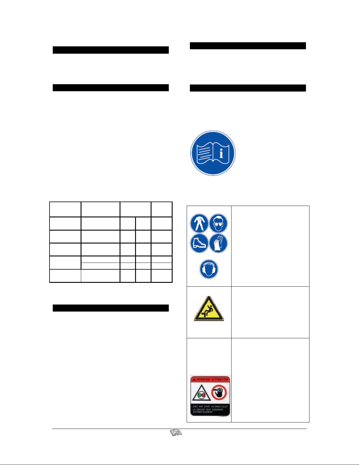
pictograms available in Carrier network.
d. If a component having a pictogram is replaced by a
new one, be sure that the new component has the right
pictogram.
e. Place a warning pictogram by applying it on a dry
surface. Press to external sides to eliminate air
bubbles.
3. PRODUCT LOADING
Proper air circulation in the insulated box, air that can
move around and through the load, is a critical
element in maintaining product quality during
transport. If air cannot circulate completely around the
load: hot spots or top-freeze can occur.
The use of pallets is highly recommended. Pallets,
when loaded so air can flow freely through the pallets
to return to the evaporator, help protect the product
from heat passing through the floor of the truck. When
using pallets, it is important to refrain from stacking
extra boxes on the floor at the rear of the truck,
because this will cut off the airflow.
Product stacking is another important factor in
protecting the product. Products that generate heat,
fruits and vegetables for example, should be stacked
so the air can flow through the product to remove the
heat; this is called "air stacking" the product. Products
that do not create heat, meats and frozen products,
should be stacked tightly in the centre of the box.
All products should be kept away from the sidewalls
of the body, allowing air to flow between the body and
the load; this prevents heat filtering through the walls
from affecting the product.
It is important to check the temperature of the product
being loaded to ensure that it is at the correct
temperature for transport. The refrigeration unit is
designed to maintain the temperature of the product at
the temperature at which it was loaded; it was not
designed to cool a warm product.
SOME ADVICE
Before loading
• Pre-cool the inside of the insulated body by lowering
the temperature for about 15 minutes.
• Evacuate the humidity existing inside the box by
carrying out a manual defrost. For CITIMAX500/700
units, the defrost mode can only take place when the
box temperature lower than 4°C.
• Evaporator fans are protected by safety grills. In the
event of heavy duty use of the unit, ice can accumulate
on the grills. It is therefore recommended to clean
them regularly by means of a small brush. The
operation MUST be done when the unit has been
SHUT DOWN.
When loading
• To be carried out with the unit stopped.
• It is recommended to open doors as little as possible
to avoid the intake of hot air and humidity.
• Select the temperature by means of the thermostat,
according to the transported goods.
• Check the internal
temperature of the goods
being loaded (using a probe
thermometer).
• Take care not to obstruct
the air intakes on the
evaporator section and the
ventilation ducts.
Load spacers
Load on pallets
• Leave a free space of about :
- 6 to 8 cm between load and front wall,
- 20 cm between the top of the load and the roof,
- between the floor and the load (gratings, pallets).
• Do not forget to close the doors.
• Before closing the doors, check your load once more
and see that nobody is
shut inside the box.
NOTE :
For stationary
utilization, we
recommend to place the
body in the shade.

62-69137-00 8
4. RECOMMENDED TRANSPORT
TEMPERATURES
Below are some general recommendations on product
transport temperatures and operating modes for the
unit. These are included for reference only and should
not be considered pre-emptive of the set-point
required by the shipper or receiver.
More detailed information can be obtained from your
Carrier Transicold dealer.
Product Set point range
Bananas 15°C (60°F)
Fresh fruits and Vegetables +4°C ~ +6°C (+39°F ~ +43°F)
Fresh meats and seafood +2°C (+36°F)
Dairy products +2°C ~ +6°C (+36°F ~ +43°F)
Ice -20°C (-4°F)
Frozen fruits and vegetables -18°C (0°F)
Frozen meats and seafood -20°C (-4°F)
Ice cream -25°C (-13°F)
It is essential to shut down the compartment during the
periods when the doors are open, in order to maintain
the temperature of the cargo in the other compartments
and keep the unit operating correctly.
5. DISPLAY BOARD
CITIMAX series provides two different display boards,
DIN display board and SMART display board, as the
following pictures show:
3 4 8 56 7 9
DIN Display
5
2
4
7
910
11
3
6
8
SMART Display
5.1. Cab control description
Keep the fold out sheet while reading the
instructions.
This functional accessory simplifies all control
operations. From your seat, you can carry out all the
control operations: shut-down, automatic start-up,
adjusting the set point, defrost, program to customize
unit operation to your own requirements, manage error
messages in event of malfunction.
You can display the box temperature and see whether
the set point is being maintained by checking the blue
or orange indicator. The malfunction indicator lights
up red in the event of malfunction. When the battery
voltage is too low, a fail-save safety system shuts
down the unit. Unit restart is automatic and
time-delayed if the voltage rises to the normal level.
DIN
SMART
1. Display
4 digits
4 digits
2. OFF key
3. Manual
defrost key
4. ON key
5. Cooling
operation LED
6. Heating
operation LED
7. Defrosting
operation LED
8. Malfunction
LED
9. + key
10. SET key
11. - key

62-69137-00 9
6. OPERATION
CITIMAX series are powered on Road mode by the
vehicle battery (alternator).
In this chapter, we will state the operation principle
respectively.
6.1 DIN Operation principle
For its big volume, we should install the DIN display
board in the fixed place of the cab cage.
After starting up, the refrigeration unit by pressing the
key, unit start-up and shut-down are
automatic.
An open-type compressor is driven by the engine of
the vehicle. The vehicle battery (alternator) powers the
evaporator and condenser fans. The unit automatically
shuts down when the engine is switched off with the
ignition key.
The unit can be completely shut down manually by
pressing the key on the cab command.
Temperature control
As soon as the set-point temperature has been reached,
temperature control is obtained by shut down and
start-up of the electro-magnetic clutch.
Condenser fan is controlled by the microprocessor and
evaporator fan(s) cut out during regulation. When
transporting fragile loads such as fresh meat,
vegetables and cheese, it is possible to program the
microprocessor to obtain continuous ventilation by the
evaporator during regulation.
Defrost -Frozen unit only
Defrost operation is fully automatic but can be
manually controlled.
- Defrost cycles are fully controlled by the integrated
microprocessor.
- During the defrost cycle, the evaporator fan shuts
down. The condenser fan is controlled by the
microprocessor.
- Defrost cycle termination is controlled by a timer or
defrost temperature sensor (DTS).
- During the defrost cycle, the cab command display
indicates "d F".
Heating - For frozen unit with heating function
option
Heating is provided by hot gas system.
The evaporator fan operates, the condenser fan is
controlled by the microprocessor.
6.1.1 To start the unit
1. Start the vehicle engine.
2. Start the unit by pressing the key. Start-up
is time-delayed for 50 seconds.
3. The digital display of the cab control displays the
box temperature.
4. Check the temperature setpoint is correct by
pressing the key. The setpoint temperature is
highlighted on the digital display.
5. Enter a new setpoint if necessary (See To change
setpoint temperature–paragraph 6.4)
In the event of difficulty on start-up, check that:
- The main road fuse has not blown. If it is ok, contact
your Carrier Service centre.
- The temperature selected by the cab control has not
been affected.
6.1.2 To stop the unit
- For a short stop (ex. delivery): switch off by the
vehicle ignition key.
- For a long stop: press the key in the cab
command.
6.1.3 To change setpoint temperature
Important
If, when settings are adjusted, no key is activated
within 5 sec. the system reverts to displaying the
box temperature. All changes made are recorded.
If the cab command is built into the vehicle control
panel, the command unit must be located as far as
possible from the heating ducts. Maximum
temperature of exposure : 85°C.
1. Press the key to display setpoint
temperature.
2. Press the or key to change the
setpoint.
3. Press the key to return to box temperature
display.

62-69137-00 10
6.1.4 To change defrost parameters
Important
If, when settings are adjusted, no key is activated
within 5 seconds, the unit will be turned off
automatically. All changes made are recorded.
1. Press the key to shut-down the unit.
2. Press simultaneously the and
keys during 5 seconds to display last selected defrost
interval.
3. Press the or key to change the
defrost time:
5 to 45 min :increase or decrease time (5, 10, 15, 20,
25, 30 and 45) (default value 10 min)
4. Press the key to display defrost interval:
0: inhibit defrost function.
1 h, 1.5h, 2 h, 2.5h, 3h, 4h, 5h and 6 h (default value
2h)
5. Press the key to return to turn off the unit.
6.1.5 To display other data (alarms,
software version, operation time, box Tº)
1. Press the key during 5 seconds to enable
access to malfunction codes (see “Fault alarm
display”– paragraph 6.8).
2. Press or key to display alarms.
3. Press the key to display controller software
version.
4. Press the key to display cab command
software version.
5. Press the key to display the total operation
time.
6. Press the key to return to box temperature
display.
6.1.6 To change default parameters
1. Press simultaneously the , and
keys to display minimum setpoint.
2. Press the or key to change
minimum setpoint : 0°C, -20°C or -29°C (default
value -29°C).
3. Press the key to display differential
parameter.
4. Press the or key to adjust the
differential value : Dif1 (1°C), Dif2 (2°C), Dif3 (3°C)
(default value Dif2).
5. Press the key to display evaporator fan
operating mode during off-cycle.
6. Press the or key to change the
evaporator fan operating mode: OFF or On (default
value OFF).
7. Press the key,to display the unit °C and °F.
8. Press the or key to change the
unit °C or °F (default value °C).
9. Press the key,to return to box temperature
display.
6.1.7 Fault alarm display
a. Access by the key
1. Press the key during 5 seconds to access to
malfunction codes.
2. Press or key to display alarms.
3. To scroll through the alarm list, use the
key.
- ACTIVE malfunctions –AXX
An alarm is active when a problem occurs on the unit,
the red LED is flashing speedily.
MALFUNCTION CODE –Red LED flashes
Code
Description
Unit shutdown
Checking
A00
No malfunction –Unit in operation
- -
Contact your
Service Center
A01
Low pressure switch open
Yes
A02
High pressure switch open
A04
Clutch open circuit
No
A06
Condenser fan short circuit
A07
Evaporator fan short circuit

62-69137-00 11
A09
Defrost valve (HGV) short circuit
A10
Liquid injection valve (INV) short circuit
A11
Main hot gas valve (MHV) short circuit
A21
Clutch short circuit
A22
Condenser fan open circuit
A23
Evaporator fan open circuit
A24
Defrost valve (HGV) open circuit
A25
Liquid injection valve (INV) open circuit
A26
Main hot gas valve (MHV) open circuit
E2P
Wrong read/write data from EEPROM
Setpoint adjusted out of range -29°C /+30°C
Lose of set parameters
b. Direct display
Note
Direct display malfunction messages are displayed instead of temperature read-out as soon as the malfunction is
detected, and remain displayed as long as malfunction persists.
The unit does not run until the malfunction has disappeared or been corrected.
Code
Description
Unit
shutdown
Checking
Mode
EE
Evaporator temperature probe
(open/short circuit)
Yes
-Evaporator probe
and connections
280/350/400/500/700
EEE
Defrost terminal temperature probe
(open/shot circuit)
No
-Defrost probe and
connections
280/350/400
bAt
Battery low voltage alarm
YES
-Battery voltage
-Alternator
connections
280/350//500/700
con
Communication malfunction
No
- Communication line
280/350/400/500/700
Err
Programming mistake of the maximum
setpoint by user
Setpoint lower than minimum setpoint
but in the range -29°C /+30°C
No
-Setpoint
280/350/400/500/700
6.2 SMART Operation principle
For its small volume, we can install the SMART
display board anywhere of the cab cage.
After starting up, the refrigeration unit by pressing the
key, unit start-up and shut-down are
automatic.
An open-type compressor is driven by the engine of
the vehicle. The vehicle battery (alternator) powers the
evaporator and condenser fans. The unit automatically
shuts down when the engine is switched off with the
ignition key.
The unit can be completely shut down manually by
pressing the key on the cab command.
Temperature control
As soon as the set-point temperature has been reached,
temperature control is obtained by shut down and
start-up of the electro-magnetic clutch.
Condenser fan is controlled by the microprocessor and
evaporator fan(s) cut out during regulation. When
transporting fragile loads such as fresh meat,
vegetables and cheese, it is possible to program the
microprocessor to obtain continuous ventilation by the
evaporator during regulation.
Defrost -Frozen unit only

62-69137-00 12
Defrost operation is fully automatic but can be
manually controlled.
- Defrost cycles are fully controlled by the integrated
microprocessor.
- During the defrost cycle, the evaporator fan shuts
down. The condenser fan is controlled by the
microprocessor.
- Defrost cycle termination is controlled by a timer or
defrost temperature sensor(DTS)..
- During the defrost cycle, the cab command display
indicates "d F".
Heating - For frozen unit with heating function
option
Heating is provided by hot gas system.
The evaporator fan operates, the condenser fan is
controlled by the microprocessor.
6.2.1 To start the unit
1. Start the vehicle engine.
2. Start the unit by pressing the key.
Start-up is time-delayed for 50 seconds.
3. The digital display of the cab control displays the
box temperature.
4. Check the temperature setpoint is correct by
pressing the key. The setpoint temperature is
highlighted on the digital display.
5. Enter a new setpoint if necessary (See To change
setpoint temperature–paragraph 6.4)
In the event of difficulty on start-up, check that:
- The main road fuse has not blown. If it is ok, contact
your Carrier Service centre.
- The temperature selected by the cab control has not
been affected.
6.2.2 To stop the unit
- For a short stop (ex. delivery): switch off by the
vehicle ignition key.
- For a long stop: press the key in the cab
command.
6.2.3 To change setpoint temperature
Important
If, when settings are adjusted, no key is activated
within 5 sec. the system reverts to displaying the
box temperature. All changes made are recorded.
If the cab command is built into the vehicle control
panel, the command unit must be located as far as
possible from the heating ducts. Maximum
temperature of exposure : 85°C.
1. Press the key to display setpoint
temperature.
2. Press the or key to change the
setpoint.
3. Press the key to return to box temperature
display.
6.2.4 To change defrost parameters
Important
If, when settings are adjusted, no key is activated
within 5 seconds, the unit will be turned off
automatically. All changes made are recorded.
1. Press the key to shut-down the unit.
2. Press simultaneously the and
keys during 5 seconds to display last selected defrost
interval.
3. Press the or key to change the defrost
time:
5 to 45 min :increase or decrease time (5, 10, 15, 20,
25, 30 and 45) (default value 10 min)
4. Press the key to display defrost interval:
0: inhibit defrost function.
1 h, 1.5h, 2 h, 2.5h, 3h, 4h, 5h and 6 h (default value
2h)
5. Press the key to return to turn off the unit.
6.2.5 To display other data (alarms,
software version, operation time, box Tº)
1. Press the key during 5 seconds to enable
access to malfunction codes (see “Fault alarm
display”– paragraph 6.8).
2. Press or key to display alarms.
3. Press the key to display controller
software version.
4. Press the key to display cab command
software version.

62-69137-00 13
5. Press the key to display the total operation
time.
6. Press the key to return to box temperature
display.
6.2.6 To change default parameters
1. Press simultaneously the , and
keys to display minimum setpoint.
2. Press the or key to change minimum
setpoint : 0°C, -20°C or -29°C (default value -29°C).
3. Press the key to display differential
parameter.
4. Press the or key to adjust the
differential value : Dif1 (1°C), Dif2 (2°C), Dif3 (3°C)
(default value Dif2).
5. Press the key to display evaporator fan
operating mode during off-cycle.
6. Press the or key to change the
evaporator fan operating mode: OFF or On (default
value OFF).
7. Press the key,to display the unit °C
and °F.
8. Press the or key to change the unit °C
or °F (default value °C).
9. Press the key,to return to box temperature
display.
6.2.7 Fault alarm display
a. Access by the key
1. Press the key during 5 seconds to access to
malfunction codes.
2. Press or key to display alarms.
3. To scroll through the alarm list, use the key.
- ACTIVE malfunctions –AXX
An alarm is active when a problem occurs on the unit,
the red LED is flashing speedily.
MALFUNCTION CODE –Red LED flashes
Code
Description
Unit shutdown
Checking
A00
No malfunction –Unit in operation
- -
Contact your
Service Center
A01
Low pressure switch open
Yes
A02
High pressure switch open
A04
Clutch open circuit
No
A06
Condenser fan short circuit
A07
Evaporator fan short circuit
A09
Defrost valve (HGV) short circuit
A10
Liquid injection valve (INV) short circuit
A11
Main hot gas valve (MHV) short circuit
A21
Clutch short circuit
A22
Condenser fan open circuit
A23
Evaporator fan open circuit
A24
Defrost valve (HGV) open circuit
A25
Liquid injection valve (INV) open circuit
A26
Main hot gas valve (MHV) open circuit
E2P
Wrong read/write data from EEPROM
Setpoint adjusted out of range -29°C /+30°C
Lose of set parameters
b. Direct display
Note
Direct display malfunction messages are displayed instead of temperature read-out as soon as the malfunction is
detected, and remain displayed as long as malfunction persists.

62-69137-00 14
The unit does not run until the malfunction has disappeared or been corrected.
Code
Description
Unit
shutdown
Checking
Mode
EE
Evaporator temperature probe
(open/short circuit)
Yes
-Evaporator probe
and connections
280/350/400/500/700
EEE
Defrost terminal temperature probe
(open/shot circuit)
No
- Defrost probe and
connections
280/350/400
bAt
Battery low voltage alarm
YES
-Battery voltage
-Alternator
connections
280/350/400/500/700
con
Communication malfunction
No
- Communication line
280/350/400/500/700
Err
Programming mistake of the maximum
setpoint by user
Setpoint lower than minimum setpoint
but in the range -29°C /+30°C
No
-Setpoint
280/350/400/500/700
7. MAINTENANCE
A comprehensive maintenance program will help to
insure that the unit continues to operate reliably. Such
a maintenance program will also help to control
operating costs, increase the unit's working life, and
improve performance.
NOTE
All maintenance services must be done by a technician
trained on Carrier products respecting all safety and
quality standards of Carrier.
Before any operation requiring an intervention on the
unit, check that:
- The unit (cab command) is OFF
- It is impossible for the unit to automatically start up
during maintenance.
7.1. Maintenance schedule
km
Mile
Initial
service
Service
A
Service
B
5000
3000
■
30000
18000
■
60000
36000
■
■
90000
54000
■
120000
72000
■
■
150000
90000
■
180000
108000
■
■
210000
126000
■
7.2. Service description
Initial service
•Check the tightness of bolts and
screws and that the unit is correctly
fastened onto the box.
•Check pressure leak.
•Check that the road compressor
RPM
•Check compressor belt tension.
Service A
•Clean up battery and battery clamps
•Check belt compressor tension
•Replace compressor belt every 3000
hours
•Check refrigerant leak
•Check all electrical connections
•Check the cooling mode
•Check the defrost operation
•Check the operation of the cab
control
•Clean up condenser coil
Service B
•Replace idler pulley bearings if any.
Every year
•Replace filter drier.
•Clean up the expansion valve orifice
filter.
Every TWO
years
•Replace compressor oil - only use
Polyolester oil (POE) approved by
Carrier Transicold.
•Replace refrigerant.
•Replace orifice expansion valve
Warning: Battery clamps must be well
positioned and tightened after
cleaning up.
Refrigerant: type R134a / R404A
Road compressor oil type: The road compressors are
supplied with CARRIER POLYOLESTER (POE) oil.
The presence of a sticker indicates that oil-change has
been correctly carried out in our Carrier Transicold

62-69137-00 15
plant.
Oils of PAG type are strictly incompatible with the
operation of our unit: never use an oil other than that
approved by Carrier.
Oil analysis: on request, we can analyze your
compressor oil.
To do this, we send a small drum with a label on
which you should indicate: the type of compressor, the
lapse time or mileage since the last oil change, the
type of Carrier equipment, the date of initial operation.
8. A.T.P. EUROPE REGULATION
EXTRACT
(Date: November 2014)
Approval of vehicles intended for the carriage of
perishable goods.
Before putting a refrigerated vehicle into service, it is
necessary to have it approved by the Regional Health
Department.
Characteristics of vehicles used for carrying perishable
goods; mechanically refrigerated equipment.
The mechanically refrigerated equipment is an
insulated unit with a cooling system which makes it
possible, with a mean outside temperature of +30°C,
to lower the temperature inside the empty body and to
maintain this low temperature in the following way:
Class A: Mechanically refrigerated equipment
furnished with a cooling system whereby a
temperature between +12°C and 0°C inclusive can be
chosen.
Class B: Mechanically refrigerated equipment
furnished with a cooling system whereby a
temperature between +12°C and–10°C inclusive can
be chosen.
Class C: Mechanically refrigerated equipment
furnished with a cooling system whereby a
temperature between +12°C and–20°C inclusive can
be chosen.
Class D: Mechanically refrigerated equipment fitted
with a refrigerating appliance such that tiis equal to or
less than 0ºC.
Class E: Mechanically refrigerated equipment fitted
with a refrigerating appliance such that tiis equal to or
less than -10ºC.
Class F: Mechanically refrigerated equipment fitted
with a refrigerating appliance such that tiis equal to or
less than -20ºC.
The cooling capacity of a unit is determined by a test
carried out in one of the approved testing stations and
ratified by an official report.
Note: The "K" coefficient of equipment of classes B,
C, E and F shall in every case be equal to or less than
0.4 W/m2. °C.
Signs, identification marks and plates to be attached to
mechanically refrigerated equipment.
Refrigeration Plate
This heavy insulation must be followed by
identification marks according to the following list:
Class A mechanically refrigerated equipment with
normal insulation FNA
Class A mechanically refrigerated equipment with
heavy insulation FRA
Class B mechanically refrigerated equipment with
heavy insulation FRB
Class C mechanically refrigerated equipment with
heavy insulation FRC
Class D mechanically refrigerated equipment with
heavy insulation FRD
Class E mechanically refrigerated equipment with
heavy insulation FRE
Class F mechanically refrigerated equipment with
heavy insulation FRF
In addition to the above identification marks, the date
(month and year) of expiry of the approval certificate
must be indicated.
Example:
FRC 06 - 2006
(06 = month (June) 2006 = year)
Very important
Regularly check the expiry date of the approval
certificate. During transport, the approval certificate or
provisional certificate should be shown on request of
qualified agents. To have an insulated unit approved
as a refrigeration unit, an application to modify the
approval certificate should be sent to the regional
health office.
9. 24HASSISTANCE
At Carrier Transicold we're working hard to give you
complete service when and where you need it. That
implies a worldwide network of dealers and available
an emergency service. These service centres are
manned by factory-trained service personnel and
backed by extensive parts inventories that will assure
you of prompt repair.
Should you encounter a unit problem with your
refrigeration unit during transit, follow your
company's emergency procedure or contact the nearest
Carrier Transicold service centre. Consult the
directory to locate the service centre nearest you. This
directory may be obtained from your Carrier

62-69137-00 16
Transicold dealer.
If you are unable to reach a service center, call Carrier
Transicold’s 24Hour Assistance:
In China, please use the below free phone numbers:
CN CHINA 4008 204909
In Europe, please use the following free phone
numbers from :
A AUSTRIA 0800 291039
B BELGIUM 0800 99310
CH SWITZERLAND 0800 838839
D GERMANY 0800 1808180
DK DENMARK 808 81832
E SPAIN 99 993213
F FRANCE 0800 913148
FIN FINLAND 0800 113221
GB GREAT BRITAIN 0800 9179067
GR GREECE 00800 3222523
H HUNGARY 06800 13526
I ITALY 800 791033
IRL IRELAND 1800 553286
L LUXEMBURG 800 3581
RUS RUSSIA 810 800 200 31032
N NORWAY 800 11435
NL THE NETHERLANDS 0800 0224894
P PORTUGAL 8008 32283
PL POLAND 00800 3211238
S SWEDEN 020 790470
From other countries / Direct : +32 9 255 67 89
In Canada or United States, call 1 –800 –448 1661
When calling, please have the following information
ready for fastest service:
• Your name, the name of your company, and your
location
• A telephone number where you can be called
back
• Refrigeration unit model and serial number
• Box temperature, setpoint and product
• Brief description for the problem you are having
and what you have already done to correct the
problem.
We will do everything we can to get your problem
taken care of and get you back on the road.

62-69137-00 17
操作说明书 中文
CITIMAX 280/350/400/500/700
前言
本说明书是针对开利运输冷冻设备有限公司制冷机组的操作人员而编写的。 本说明书除了
包含制冷机组的日常操作方面的基本步骤以外,还包含安全信息、故障排除的技巧以及其它信
息等,而这些信息可以帮助您确保运输货物的最佳新鲜度。
请仔细阅读本说明书所述的全部内容,当您对所购买的开利运输冷冻设备产品在操作方面
有不解之处时,请随时参考本说明书。本说明书适用于标准型号的产品。本说明书或许没有包
含部分备选件;对这些备选件的信息,请向本公司的技术服务部咨询。
只要对所购买的本公司的制冷机组产品进行正确的操作和保养,此机组可以长期、无故障
运行。本说明书中所概述的检查方法会帮助您将问题减小到最低程度。此外,综合保养程序会
帮助您保证机组的持续、可靠的运行。此保养程序还可以帮助控制此机组的运行费用,延长机
组的使用寿命,并提高其性能。
对机组进行维修的时候,请务必使用指定的开利运输冷冻设备公司的原装备用零件,以保
障其最佳质量和可靠性。
开利运输冷冻设备有限公司的全体员工正不断地提高产品性能,以满足客户的需要。因此,
产品规格如发生变更,恕不另行通知。
目录
前言.......................................................................................................................................................17
1. 产品说明和产品标识..............................................................................................................18
1.1. 产品说明.......................................................................................................................18
1.2. 产品标识牌...................................................................................................................18
1.3. 噪声等级标签...............................................................................................................18
2. 安全说明..................................................................................................................................18
2.1. 警告标签的保养...........................................................................................................20
3. 货物装载说明..........................................................................................................................21
4. 运输温度(推荐)..................................................................................................................22
5. 显示板......................................................................................................................................22
5.1. 操作面板说明...............................................................................................................22
6. 操作说明..................................................................................................................................23
6.1 DIN 显示器操作原理.....................................................................................................23
6.2 SMART 操作原理 ..........................................................................................................25
7. 保养说明..................................................................................................................................28
7.1. 保养计划.......................................................................................................................28
7.2. 维修说明.......................................................................................................................28
8. A.T.P. 欧洲法规摘要 ..............................................................................................................29
9. 24 小时服务热线...................................................................................................................30

62-69137-00 18
1. 产品说明和产品标识
阅读说明书时请保存好折页部分,免得
不小心被撕掉。
1.1. 产品说明
CITIMAX 系列机组设计简单、可靠而
且已经过各种试验;运行费用低,可装在大、
中和小型货车上。
此机组为分体式系统,可以适用于任何
型号的车辆以及任何结构。
a. 蒸发器
b. 冷凝器
c. 驾驶室控制装置
d. 与汽车相接部分所使用的保险丝
e. 成套的系列安装配件包
CITIMAX 系列机组选型时请注意:
制冷剂
风机
类型
CITIMAX 280
R404A
12V
24V
Frozen
CITIMAX 350
R404A
12V
24V
Frozen
CITIMAX 400
R404A
12V
24V
Frozen
CITIMAX 500
R134a
12V
24V
Fresh
R404A
12V
24V
Frozen
CITIMAX 700
R404A
12V
24V
Frozen
■我公司提供的种类丰富的成套配件使得这
些机组适用于大部分的车辆。
1.2. 产品标识牌
各机组通过贴在机框架上的标识牌进
行识别。标识牌上有机组完整的型号、系列
号以及其它一些信息。如果机组出现故障,
请查看标识牌上的信息并把型号和系列号
记下,然后打电话寻求帮助。联系技术人员
之后请提供这些信息,好让他们提供正确帮
助。很容易在机组架上找到完整的标识牌
(1a),也很容易在机组的侧面找到附加的系
列号(1b)。
1.3. 噪声等级标签
噪声等级标签显示噪声等级(单位
Lwa(声功率级))。
2. 安全说明
本说明书包含安全以及维修方面的操
作步骤,用户须遵守这些步骤以免事故发生。
以下标签中的一些标签已贴在产品上,以提
示安全信息。
使用本制冷机组之前,
先仔细阅读本说明书中所
述的以及产品上标有的全
部的安全信息。 使用本制
冷机组的任何人员必须提
前接受培训,然后才可以
安全地使用本机组。
使用或保养本制冷机组的过程中,须留意安
全方面的注意事项。
个人防护装备:
如本说明书中所述,对本制冷
机组进行任何操作之前,需穿
戴适当的个人防护装备。
●机组运转时建议戴上听力
保护装置。
高空作业:
接近本制冷机组时,须采取所
有的安全预防措施。使用配有
适当的防护装置的安全梯和
工作台。
自动起动:
本制冷机组设有自动起动/停
止功能,能有效节约燃料。即:
当厢体达到设定温度时,机组
自动停止运行;当厢体偏离设
定温度时,机组又会自动起动
运行。
对制冷机组进行维修之前,先
确认机组处于关机状态,确

62-69137-00 19
保机组不会重新起动。
断开或封闭以下部位,进行断
电上锁并标记。
发动机驱动模式下蓄电
池负极电缆并上锁
电气:
本制冷机组在电力运行状态
下运转时,一些部件,尤其是
电控箱会带电。
对电气装置进行操作时,必须
使用适当的工具而且穿戴合
适的个人防护装备:安全手套
以及防护眼镜。
对制冷机组进行维修之前,先
确认机组处于关机状态。
确保本制冷机组与任何供电
设备断开连接。如上述,对机
组的电源处进行上锁并标识
(Lock out/tag out)。对控制箱
内部进行操作之前,必须确认
控制箱不带电(absence of
tension)。
对电容器进行维修之前,先将
所有的电容器放电以免发生
电击。
对不得不在控制箱带电状态
下进行操作时,操作人员必须
具备允许在低电压/高电压环
境中进行作业的资格证。
冷冻油:
避免长时间或多次的
皮肤接触。
处理后应仔细地洗干
净。
皮带与风扇:
本制冷机组设有自动起动/
停止功能,会随时起动,不
发出任何警告。
当机组正在运转时,当心转动的皮带及风扇。 对制
冷机组进行维修之前,先确认机组处于关机状态。
确保机组不会重新起动。 如上述,对机组的电源处
进行上锁并标识(Lock out/tag out)。
如有防护结构(例如,风扇格栅或防护装置等),
确认它们是否装在适当的位置。制冷机组正在运转
时,千万不要拆卸这些防护结构。
操作人员的手、身体部位、衣服、头发以及工具等
必须远离转动部件。
制冷剂:
本制冷机组内
的制冷剂如果
喷到或直接触
到皮肤或眼
睛,会导致冻
伤、严重烧伤
或失明。
制冷剂如果接触到火焰或热,会产生有毒气体: 任
何火焰、被点燃物或火苗都要远离制冷机组。
处理制冷剂
时,必须穿戴
个人防护装
备: 防护服、
防护手套以及
防护眼镜。
有资格的人员才能进行制冷剂的处理作业。
制冷剂的使用与处理方法
•可燃性:HCFC 制冷剂与压力升高时的高浓度空气
进行混合便变成可燃物;此制冷剂包括R-134a 和
R404A。
• 因此,在泄漏检查或其它用途上,这些制冷剂不
可与压力状态下的空气进行混合。
• 呼吸危害性: 如果吸入的制冷剂浓度超过安全限
量(推荐),任何制冷剂都会对身体有危害。 出现
的症状如下:
头痛、作呕、困倦、嗜睡、头晕以及共济失调等。 此
外,可以导致心律不齐、意识不清,甚至死亡。 应
采取正确的方法,使自己尽量减少与制冷剂环境接
触。
• 火焰变大:在有制冷剂蒸汽的情况下进行熔接或
焊接时,如果发现火焰的颜色或大小发生变化,立
即停止作业并对该区域进行通风。只有在制冷剂蒸
汽的浓度达到危险值的时候,火焰才会发生这种变
化。火焰的这种变化会导致上述窒息等现象。
皮肤/眼睛的保护:接触到“液状”制冷剂会使身体

62-69137-00 20
组织立刻凝固起来,相继会导致永久性损伤或失明。
进行液状制冷剂的处理作业时,一定要穿戴适当的
个人防护装备。 不要切割压力状态下的制冷剂管
道。 不要打开阀门或换气设备,否则,液状制冷剂
会喷到操作人员的身上。
烧伤及冻伤:
本制冷机组正在运转的
过程中 或 甚 至运 转 之
后,各种部件的温度仍
会非常低或非常高(例
如,排气管、管道、盘
管、贮液器、汽液分离
器或发动机等)。
在低温或高温部件的周
围进行操作时要多加小
心。
对本制冷机组进行保养
作业时,必须戴上适当
的防护手套。
切边:
在可能导致受伤的部件
(例如,盘管、蒸发器、
套管夹等)的周围进行
处理或操作作业时要多
加小心。
对本制冷机组进行保养
作业时,必须戴上适当
的防护手套。
蓄电池:
本制冷机组可能装
有铅酸蓄电池。 对
蓄电池进行充电时
一般会放出少量的
易燃、易爆的氢气。
酸喷射到皮肤或眼
睛会引起严重的烧
伤。
任何火焰、被点燃物
或火苗都要远离蓄
电池元件。
对蓄电池进行处理
及充电时,必须穿戴
个人防护装备: 防
护服、防护手套以及
防护眼镜。
蓄电池极性的连接
须正确。
当心
任何人在任何情况
下都不允许试图 维
修逻辑板或显示板。
如果这些部件发生
问题,请与当地的开
利运输冷冻设备经
销商取得联系并更
换部件。
技术人员决不能对处理器的任何部位进行电路方面
的检查,他只能对接线端子(即线束连接的地方)
进行检查。微处理器元件在不同的电压以及超低电
流状态下正常运行。 电压表、跳线、断路探查试验
器等装置的不正确使用会导致微处理器永久性损
坏。
大部分电子元件容易遭受由静电释放(ESD)引起
的损坏。
有时,人体本身也可以携带充分的静电,以致人体
一接触电子元件就会对其造成损坏。这种现象在卡
车/拖车微处理器的集成电路上特别明显。
环境:
本制冷机组的整个使用寿
命期间都要考虑环保问题。
为了预防环境污染,不要将
制冷剂排放到大气中,不要
将冷却液、油、蓄电池以及
化学物质丢弃到大自然中。
须按照现有的法规对其进
行回收、再生处理。
废弃本制冷机组时,要采用
环境保护型方法而且要遵
守现有的法规。
2.1. 警告标签的保养
a. 将警告图保持干净并保证警告图标不被
任何物体遮挡。
This manual suits for next models
4
Table of contents
Other Carrier TRANSICOLD Cooling Box manuals
Popular Cooling Box manuals by other brands

FRIEDHELM LOH
FRIEDHELM LOH Rittal SK 3178800 Assembly and operating instructions

Dometic
Dometic TROPICOOL TCX07 operating manual

CARLO GAVAZZI
CARLO GAVAZZI RHS Series Mechanical Assemblies

TriStar
TriStar KB-7424 user manual

Dometic
Dometic CFX 100 Professional operating manual

Zanotti
Zanotti MAS121 T118S quick start guide