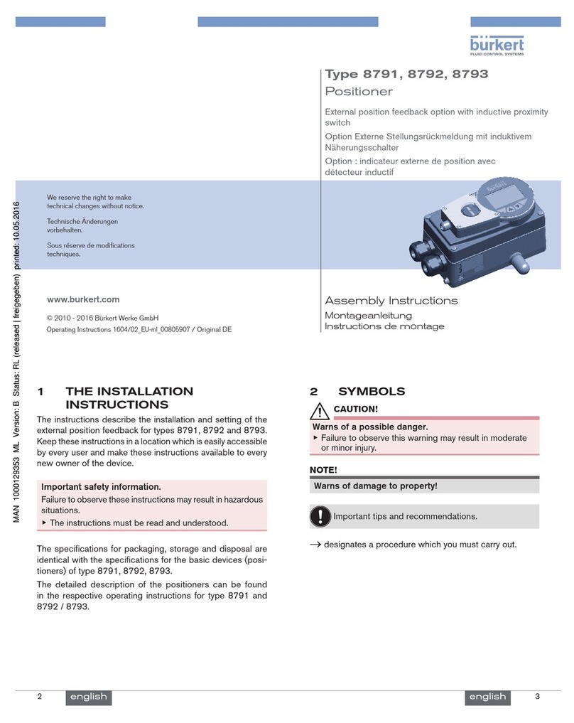
Bürkert 8696 User manual

Operating Instructions
Bedienungsanleitung
Manuel d‘ utilisation
Type 8696
Positioner TopControl Basic
Electropneumatic Position Controller
Elektropneumatischer Stellungsregler
Positionneur électropneumatiques

We reserve the right to make technical changes without notice.
Technische Änderungen vorbehalten.
Sous réserve de modifications techniques.
© 2008 - 2014 Bürkert Werke GmbH
Operating Instructions 1411/08_EU-ML_00805905 / Original DE

3
Table of ConTenTs
1 OPERATING INSTRUCTIONS ........................................................................................................................................................7
1.1 Symbols ......................................................................................................................................................................................7
1.2 Definition of term / abbreviation ...................................................................................................................................7
2 AUTHORIZED USE .............................................................................................................................................................................8
2.1 Restrictions ...............................................................................................................................................................................8
3 BASIC SAFETY INSTRUCTIONS .................................................................................................................................................9
4 GENERAL INFORMATION .............................................................................................................................................................10
4.1 Contact address ..................................................................................................................................................................10
4.2 Warranty ...................................................................................................................................................................................10
4.3 Trademarks ............................................................................................................................................................................10
4.4 Information on the internet ............................................................................................................................................10
5 SYSTEM DESCRIPTION ................................................................................................................................................................11
5.1 Designated application area .........................................................................................................................................11
5.2 Function of the positioner and combination with valve types ....................................................................11
5.3 Features of the valve types ...........................................................................................................................................12
5.4 Model for control of third-party devices .................................................................................................................13
5.5 Structure of the positioner ............................................................................................................................................14
5.5.1 Representation ....................................................................................................................................14
5.5.2 Features ................................................................................................................................................15
5.5.3 Functional diagram of the positioner with single-acting actuator ...........................................16
5.6 Type 8696 positioner .........................................................................................................................................................17
5.6.1 Schematic representation of the position control Type 8696 ..................................................17
5.6.2 Functions of the positioner software ..............................................................................................18
5.7 Interfaces of the positioner ..........................................................................................................................................20
Positioner Type 8696
english
Type 8686

4
6 TECHNICAL DATA .............................................................................................................................................................................21
6.1 Conformity ..............................................................................................................................................................................21
6.2 Standards ................................................................................................................................................................................21
6.3 Licenses ...................................................................................................................................................................................21
6.4 Operating conditions ........................................................................................................................................................21
6.5 Mechanical data ...................................................................................................................................................................21
6.6 Pneumatic data ....................................................................................................................................................................22
6.7 Type label ................................................................................................................................................................................22
6.8 UL additional label ..............................................................................................................................................................23
6.9 Electrical data .......................................................................................................................................................................23
6.10 Factory settings of the positioner ..............................................................................................................................24
7 CONTROL AND DISPLAY ELEMENTS ...................................................................................................................................25
7.1 Operating status ...................................................................................................................................................................... 25
7.2 Control and display elements of the positioner .................................................................................................25
7.3 Configuration of the keys ................................................................................................................................................... 26
7.4 Function of the DIP switches ........................................................................................................................................... 28
7.5 Display of the LEDs ............................................................................................................................................................... 30
7.6 Error messages ....................................................................................................................................................................... 31
7.6.1 Error messages in MANUAL and AUTOMATIC operating statuses .........................................31
7.6.2 Error messages while the X.TUNE function is running ..............................................................31
8 INSTALLATION ...................................................................................................................................................................................32
8.1 Safety instructions .............................................................................................................................................................32
8.2 Installation of the positioner Type 8696 to process valves of series 2103, 2300 and 2301 ......32
8.3 Rotating the actuator module for process valves belonging to series 2300 and 2301 ................36
9 PNEUMATIC INSTALLATION .......................................................................................................................................................38
10 ELECTRICAL INSTALLATION 24 V DC ...................................................................................................................................40
10.2 Electrical installation with circular plug-in connector .....................................................................................41
english
Type 8696

5
10.2.1 Designation of the contacts Type 8696 ........................................................................................41
10.2.2 Connection of the positioner Type 8696 ......................................................................................41
11 START-UP .............................................................................................................................................................................................43
11.1 Safety instructions .............................................................................................................................................................43
11.2 Specifying the standard settings ................................................................................................................................43
11.2.1 Running the automatic adjustment X.TUNE .........................................................................43
12 OPERATION AND FUNCTION ....................................................................................................................................................45
12.1 Basic functions ........................................................................................................................................................................ 45
12.1.1 DIR.CMD -
Effective direction of the positioner set-point value ...................................................................46
12.1.2 CUTOFF -
Sealing function for the positioner .................................................................................................47
12.1.3 CHARACT -
Select the transfer characteristic between input signal (position set-point value) and
stroke .....................................................................................................................................................48
12.1.4 INPUT -
Enter the input signal .........................................................................................................................50
12.1.5 RESET -
Reset to factory settings ...................................................................................................................51
12.1.6 X.TUNE -
Automatic adjustment of the positioner to the relevant operating conditions ......................51
12.2 Auxiliary functions .................................................................................................................................................................. 52
12.2.1 DIR.ACTUATOR -
Effective direction of the actuator ...................................................................................................52
12.2.2 SPLITRANGE -
Signal split range ................................................................................................................................53
12.2.3 X.LIMIT -
Limiting the mechanical stroke range ............................................................................................54
12.2.4 X.TIME -
Limiting the control speed ................................................................................................................55
12.2.5 X.CONTROL -
Parameterization of the positioner ..................................................................................................56
12.2.6 SAFE POSITION -
Definition of the safe position ..........................................................................................................56
12.2.7 SIGNAL ERROR -
Configuration of signal level fault detection .................................................................................57
12.2.8 BINARY INPUT -
Activation of the binary input ...........................................................................................................57
12.2.9 OUTPUT (optional) -
Configuration of the analog output ................................................................................................58
english
Type 8696

6
13 SAFETY END POSITIONS ............................................................................................................................................................59
13.1 Safety end positions after failure of the electrical or pneumatic auxiliary power ...........................59
14 MAINTENANCE ..................................................................................................................................................................................59
15 DISASSEMBLY ...................................................................................................................................................................................60
15.1 Safety instructions .............................................................................................................................................................60
15.2 Disassembly the positioner ...........................................................................................................................................60
16 ACCESSORIES ..................................................................................................................................................................................62
16.1 Communications software .............................................................................................................................................62
16.1.1 USB interface ......................................................................................................................................62
16.1.2 Download .............................................................................................................................................62
17 PACKAGING AND TRANSPORT ...............................................................................................................................................63
18 STORAGE ..............................................................................................................................................................................................63
19 DISPOSAL ............................................................................................................................................................................................63
english
Type 8696

7
Operating instructions
1 OPERATING INSTRUCTIONS
The operating instructions describe the entire life cycle of the device. Keep these instructions in a location which is easily
accessible to every user and make these instructions available to every new owner of the device.
Important safety information.
Read the operating instruction carefully and thoroughly. Study in particular the chapters entitled “Basic safety
instructions” and “Authorized use”.
▶The operating instructions must be read and understood.
1.1 Symbols
DANGER!
Warns of an immediate danger.
▶Failure to observe the warning may result in a fatal or serious injury.
WARNING!
Warns of a potentially dangerous situation.
▶Failure to observe the warning may result in serious injuries or death.
CAUTION!
Warns of a possible danger.
▶Failure to observe this warning may result in a moderately severe or minor injury.
NOTE!
Warns of damage to property.
1. Failure to observe the warning may result in damage to the device or the equipment.
Indicates important additional information, tips and recommendations.
refers to information in these operating instructions or in other documentation.
▶Designates an instruction to prevent risks.
→Designates a procedure which you must carry out.
1.2 Definition of term / abbreviation
The term “device” used in these instructions always stands for the positioner Type 8696.
In these instructions, the abbreviation “Ex” always refers to “potentially explosive”.
english
Type 8696

8
Authorized use
2 AUTHORIZED USE
Incorrect use of the positioner Type 8696 may be a hazard to people, nearby equipment and the
environment.
▶The device is designed to be mounted on pneumatic actuators of process valves for the control of media.
▶Do not expose the device to direct sunlight.
▶Use according to the permitted data, operating conditions and conditions of use specified in the contract
documents and operating instructions. These are described in the chapter entitled “6 Technical data”.
▶The device may be used only in conjunction with third-party devices and components recommended and
authorized by Bürkert.
▶In view of the large number of options for use, before installation, it is essential to study and if necessary to
test whether the positioner is suitable for the actual use planned.
▶Correct transportation, correct storage and installation and careful use and maintenance are essential for reli-
able and problem-free operation.
▶Use the positioner Type 8696 only as intended.
2.1 Restrictions
If exporting the system/device, observe any existing restrictions.
english
Type 8696

9
Basic safety instructions
3 BASIC SAFETY INSTRUCTIONS
These safety instructions do not make allowance for any
• contingencies and events which may arise during the installation, operation and maintenance of the devices.
• local safety regulations; the operator is responsible for observing these regulations, also with reference to the
installation personnel.
DANGER!
Risk of injury from high pressure in the equipment/device.
▶Before working on equipment or device, switch off the pressure and deaerate/drain lines.
Risk of electric shock.
▶Before working on equipment or device, switch off the power supply and secure to prevent reactivation.
▶Observe applicable accident prevention and safety regulations for electrical equipment.
General hazardous situations.
To prevent injury, ensure that:
▶In the potentially explosion-risk area the positioner Type 8696 may be used only according to the specification
on the separate approval sticker. For use observe the additional instructions enclosed with the device together
with safety instructions for the explosion-risk area.
▶Devices without a separate approval sticker may not be used in a potentially explosive area.
▶The system cannot be activated unintentionally.
▶Installation and repair work may be carried out by authorised technicians only and with the appropriate tools.
▶After an interruption in the power supply or pneumatic supply, ensure that the process is restarted in a defined
or controlled manner.
▶The device may be operated only when in perfect condition and in consideration of the operating instructions.
▶The general rules of technology apply to application planning and operation of the device.
To prevent damage to property of the device, ensure:
▶Do not feed any aggressive or flammable media into the pilot air port.
▶Do not feed any liquids into the pilot air port.
▶When unscrewing and screwing in the body casing or the transparent cap, do not hold the actuator of the pro-
cess valve but the connection housing of Type 8696.
▶Do not put any loads on the body (e.g. by placing objects on it or standing on it).
▶Do not make any external modifications to the device bodies.
english
Type 8696

10
Basic safety instructions
NOTE!
Electrostatic sensitive components / modules.
The device contains electronic components which react sensitively to electrostatic discharge (ESD). Contact
with electrostatically charged persons or objects is hazardous to these components. In the worst case scenario,
they will be destroyed immediately or will fail after start-up.
▶Observe the requirements in accordance with EN 100 015 - 1 to minimise or avoid the possibility of damage
caused by sudden electrostatic discharge.
▶Also ensure that you do not touch electronic components when the power supply voltage is present.
4 GENERAL INFORMATION
4.1 Contact address
Germany
Bürkert Fluid Control System
Sales Centre
Chr.-Bürkert-Str. 13-17
D-74653 Ingelfingen
Tel. + 49 (0) 7940 - 10 91 111
Fax + 49 (0) 7940 - 10 91 448
E-mail: [email protected]
International
Contact addresses can be found on the final pages of the printed operating instructions.
And also on the internet at:
www.burkert.com
4.2 Warranty
The warranty is only valid if the positioner Type 8696 is used as intended in accordance with the specified appli-
cation conditions.
4.3 Trademarks
Brands and trademarks listed below are trademarks of the corresponding companies / associations /
organizations
Loctite Henkel Loctite Deutschland GmbH
4.4 Information on the internet
The operating instructions and data sheets for Type 8696 can be found on the Internet at:
www.burkert.com
english
Type 8696

11
System description
5 SYSTEM DESCRIPTION
5.1 Designated application area
The positioner Type 8696 is designed to be mounted on pneumatic actuators of process valves for the control of
media.
5.2 Function of the positioner and combination with
valve types
Positioner Type 8696 is an electropneumatic position controller for pneumatically actuated control valves with
single-acting actuators.
Together with the pneumatic actuator, the positioner forms a functional unit.
The control valve systems can be used for a wide range of control tasks in fluid technology and, depending on the
application conditions, different process valves from the Bürkert range can be combined with the positioner. Angle
seat valves, straight seat valves or diaphragm valves of the Type 2300, 2301 or 2103 with an actuator size of 50
mm are suitable.
“Figure 1” shows an overview of the possible combinations of positioner and different pneumatically actuated valves.
Different valve orifices, not illustrated here, are available for each type. More precise specifications can be found on
the respective data sheets. The product range is being continuously expanded.
Positioner
Type 8696
with angle seat valve
with diaphragm valve
Figure 1: Overview of possible combinations
english
Type 8696

12
System description
The position of the actuator is regulated according to the position set-point value. The nominal position value is
specified by an external standard signal.
Pneumatically actuated piston actuators and rotary actuators can be used as an actuator. Single-acting actuators
are offered in combination with the positioner.
For single-acting actuators, only one chamber is aerated and deaerated during actuation. The generated pressure
works against a spring. The piston moves until there is an equilibrium of forces between compressive force and
spring force.
5.3 Features of the valve types
Angle seat control valves / Straight seat
control valves Diaphragm Valves
Types • 2300
• 2301
• 2103
Features • incoming flow under seat
• no pressure surges when closing the valve
• straight flow path of the medium
• self-adjusting packing gland for high
leak-tightness
• medium is hermetically separated from the
actuator and environment
• cavity-free and self-draining body design
• any flow direction with low-turbulence flow
• steam-sterilizable
• CIP-compliant
• no pressure surges when closing the valve
• actuator and diaphragm can be removed
when the housing is installed
Typical media • water, steam and gases
• alcohols, oils, propellants, hydraulic fluids
• salt solutions, lyes (organic)
• solvents
• neutral gases and liquids
• contaminated, abrasive and aggressive
media
• media of higher viscosity
Table 1: Features of the valve types
english
Type 8696

13
System description
5.4 Model for control of third-party devices
A special model enables the positioner Type 8696 to be attached to third-party devices.
This model has a different pneumatic connection housing so that the pilot air ports can be connected to the
outside of the actuator.
Electrical connection
(circular plug-in connector)
Exhaust air port
(label: 3)
Pilot air port
(label: 1)
Fastening screws (2 x)
Pilot air outlet 22
Pilot air outlet 21
Connection housing
Figure 2: Model for third-party devices
NOTE!
Damage or malfunction due to ingress of dirt and moisture.
▶To comply with degree of protection IP65 / IP67, connect the pilot air outlet (only for CFA or CFB) which is
not required to the free pilot air port of the third-party device or seal with a plug.
“In rest position” means that the pilot valves of the positioner Type 8696 are isolated or not actuated.
If the ambient air is humid, a hose can be connected between pilot air outlet 22 of the positioner and the
unconnected pilot air port of the third-party device for control function A or control function B. As a result,
the spring chamber of the third-party device is supplied with dry air from the vent duct of the positioner.
Control function (CF) Pneumatic connection
Type 8696 with third-party device
AProcess valve closed in rest position
(by spring force)
Pilot air outlet 21
22
1)
BProcess valve open in rest position
(by spring force)
Pilot air outlet 21
22
1)
Table 2: Pneumatic connection to third-party device
1) Connection optionally, see note.
english
Type 8696

14
System description
5.5 Structure of the positioner
The positioner Type 8696 consists of the micro-processor controlled electronics, the position measuring system
and the control system.
The appliance is designed using three-wire technology. The operation of the positioner takes place via 2 keys and
a 4-pole DIP switch.
The pneumatic control system for single-acting actuators consists of two solenoid valves.
5.5.1 Representation
Key 1
DIP Switches
Key 2
Pilot air port
(label: 1)
Connection housing
Exhaust air port
(label: 3)
Electrical connection
(circular plug-in connector
M12 x 1)
Transparent cap removed:
LED
Pressure limiting valve
(for protection against too
high internal pressure in
case of error)
Communications
interface
Figure 3: Structure
english
Type 8696

15
System description
5.5.2 Features
• Models
for single-acting valve actuators.
• Position measuring system
Non-contact and therefore non-wearing position measuring system.
• Microprocessor-controlled electronics
for signal processing, control and valve control.
• Control module
The operation of the device takes place via 2 keys and a 4-pole DIP switch. 2 2-colored LEDs allow various
status displays of the device.
• Control system
The control system consists of 2 solenoid valves. One valve is used to aerate and another to deaerate the pneu-
matic actuator. The solenoid valves operate according to the rocker principle and are controlled with a PWM
voltage via the controller. Doing so achieves a higher flexibility with regard to actuator volume and final control
speed. The direct-action model has an orifice of DN 0.6.
• Position feedback (optional)
The position of the valve can be relayed to the PLC via an analogue 0/4 – 20 mA output.
• Binary input
If a voltage > 10 V is applied, SAFE POSITION is activated, i.e. the valve is moved to the safety position
(factory setting, can be changed with communications software).
• Pneumatic interfaces
hose plug-in connection ∅ 6 mm / 1/4“
on request: threaded port
• Electrical interfaces
Circular plug-in connection
• Body
The body of the positioner is protected from excessively high internal pressure, e.g. due to leaks, by a pressure
limiting valve.
• Communications interface
For configuration and parameterization.
english
Type 8696

16
System description
5.5.3 Functional diagram of the positioner with single-acting
actuator
The displayed functional diagram describes the function of the positioner (Type 8696).
Control system
1
2
Position
controller
Control system
1: Aeriation valve
2: Bleed valve
Pressure
supply
Exhaust air
Position
measuring
system
Actual
position
External
position
set-point value
Positioner
Pneumatic
actuator
(single-acting)
Valve
(actuator)
Figure 4: Function diagram
english
Type 8696

17
System description
5.6 Type 8696 positioner
The position measuring system records the current position (POS) of the pneumatic actuator. The positioner com-
pares this actual position value with the set-point value (CMD), which is definable as norm signal. In case of a control
deviation (Xd1), a pulse-width modulated voltage signal is sent to the control system as a manipulated variable. If
there is a positive control difference in single-acting actuators, the air inlet valve is controlled via output B1. If the
control difference is negative, the bleed valve is controlled via output E1. In this way the position of the actuator is
changed until control difference is 0. Z1 represents a disturbance variable.
Valve opening
Control valveControl system
Solenoid valves
Position measuring system
Position
controller
Position
set-point
value
CMD Xd1 B1
E1 PK
Z1
POS
Position control circuit
+-
Figure 5: Signal flow plan of positioner
5.6.1 Schematic representation of the position control Type 8696
4 ... 20 mA2)
0 ... 20 mA
CHARACT
SPLTRNG3)
DIR.CMD CUTOFF X.TIME3)
X.CONTROL
DBND
POS
CMD
INP
POS
CMD
DIR.ACT3) X.LIMIT3)
2) Default setting
3) can only be activated with communications software
Figure 6: Schematic representation of the position control
english
Type 8696

18
System description
5.6.2 Functions of the positioner software
Functions I
• Activation via DIP switches
• Parameter setting via communications software
Additional function Effect
Sealing function
CUTOFF
Valve closes tight outside the control range. Specification
of the value (as %), from which the actuator is completely
deaerated (when 0 %) or aerated (when 100 %)
(see chapter “7.4 Function of the DIP switches”).
Correction line to adjust the operating characteristic
CHARACT
Linearization of the operating characteristic can be imple-
mented (see chapter “7.4 Function of the DIP switches”).
Effective direction of the controller set-point value
DIR.CMD
Reversal of the effective direction of the set-point value
(see chapter “7.4 Function of the DIP switches”).
Table 3: Functions I
english
Type 8696

19
System description
Functions II
• Activation and parameter setting via communications software
Additional function Effect
Standard signal for set-point value
INPUT Select set-point value standard signal
Effective direction of the actuator
DIR.ACTUATOR
Assignment of the aeration status of the actuator
chamber to the actual position.
Signal split range
SPLITRANGE
Standard signal as % for which the valve runs through
the entire mechanical stroke range.
Mechanical stroke range limit
X.LIMIT Limit the mechanical stroke range
Opening and closing time
X.TIME Limit the control speed
Positioner
X.CONTROL Parameterize the positioner
Safety position
SAFE POSITION Definition of the safety position
Signal level fault detection
SIGNAL ERROR Configuration of signal level fault detection
Binary input
BINARY INPUT Configuration of the binary input
Analog output
OUTPUT Configuration of the analog output (optional)
Reset
RESET Reset to factory settings
Table 4: Functions II
english
Type 8696

20
System description
5.7 Interfaces of the positioner
Input for position
set-point value
4 – 20 mA4)
0 – 20 mA
Binary input
24 V DC
Communications
interface
Positioner
Analog
position feedback
(optional)
Inputs
Outputs
Power
Operation
4) default setting
Figure 7: Interfaces
The positioner Type 8696 is a 3-wire device, i.e. the power (24 V DC) is supplied separately from the set-
point value signal.
• Input for position set-point value (4 – 20 mA corresponds to 0 – 100%)
(depending on the position of DIP switch 1)
• Binary input
If a voltage > 10 V is applied, SAFE POSITION is activated, i.e. the valve is moved to the safety position
(factory setting, can be changed with communications software)
• Analog position feedback (optional)
The position of the valve can be transmitted via an analog 4 – 20 mA output to the PLC
(4 – 20 mA corresponds to 0 – 100%)
english
Type 8696
Other manuals for 8696
2
Table of contents
Languages:
Other Bürkert Valve Positioner manuals
Popular Valve Positioner manuals by other brands

Omron
Omron 3F88L-160 user manual

Samson
Samson TROVIS 3730-1 Mounting and operating instructions

Siemens
Siemens SIPART PS2 Technical description

Aventics
Aventics AB-1 Service information

ABB
ABB PositionMaster EDP300 manual

GEM
GEM C67 CleanStar Installation, Operating and Maintenance Instructions for the Installer and the User