BAC RC Series User manual

www.BaltimoreAircoil.com.au
120 Wisemans Ferry Road, Somersby NSW 2250 › Telephone (Australia): 1300.134.622 › Telephone (New Zealand): 0800.225.842
RIGGING & ASSEMBLY INSTRUCTIONS
RC Series
RCF
RCC

RC series coil products should be rigged and
assembled as outlined in this bulletin.
These procedures should be thoroughly reviewed prior to the
actual rigging and assembly of the equipment to acquaint all
personnel with procedures to be followed and to ensure that all
necessary equipment will be available beforehand.
If outstanding circumstances require a departure from the
procedures outlined in this manual, contact your local BAC
Representative for guidance.
Be sure to have a copy of the submittal drawings available for reference.
If you do not have a copy of these drawings, or if you need additional
information about this unit, contact your local BAC Representative whose
name and telephone number are on the outside of the cold water basin. The
model number and serial number of the unit are also located in this area.

WWW.BALTIMOREAIRCOIL.COM.AU
1
MAR208-0
RIGGING & ASSEMBLY INSTRUCTIONS » RC SERIES
1 Introduction
2 Safety
2 Shipping
2 Pre-Rigging Checks
3 Cold Weather Operation
3 Location
3 Warranties
3 Unit Operation
2 Unit Rigging & Assembly
4 Rigging
5 Section Assembly
7 Field Sealing of Basin to Casing Post Joint
8 Fitting of Pump and Piping
9 Roof Deck Section Lifting
3 Optional Accessory & Loose Item Installation
10 Air Inlet Louvres
10 Float Valve
11 Fitting Tie Braces
12 Fitting of Wind Walls
13 Piping
13 Fan Speed
13 Bleed Line Installation
14 Platform Installation
4 Final Assembly Details
16 Inspection
16 Piping
16 Fan Speed
16 Freeze Protection
Table of Contents

WWW.BALTIMOREAIRCOIL.COM.AU
2
MAR208-0
1RC SERIES
Introduction
Safety
Adequate precautions appropriate for the installation and location
of these products should be taken to safeguard the equipment and
the premises from damage and the public from possible injury. The
procedures listed in this manual must be thoroughly reviewed prior to
rigging and assembly. Read all warnings, cautions, and notes detailed
in the margins.
When the fan speed of the unit is to be changed from the factory set
speed, including the use of a variable speed device, steps must be
taken to avoid operating at or near the fan’s “critical speed” which
could result in fan failure and possible injury or damage. Consult with
your local BAC Representative on any such applications.
Shipping
BAC RC Series units are factory assembled to ensure uniform quality
with minimum eld assembly. As standard, models ship in two sections
per cell (lower and upper). Optional shipment of three sections per
cell and optional containerized shipments are available. Contact your
local BAC Representative for more information. For the dimensions and
weights of a specic unit or section, refer to the submittal drawings.
Pre-Rigging Checks
When the unit is delivered to the jobsite, it should be checked
thoroughly to ensure all required items have been received and are free
of any shipping damage prior to signing the bill of lading.
The following parts should be inspected:
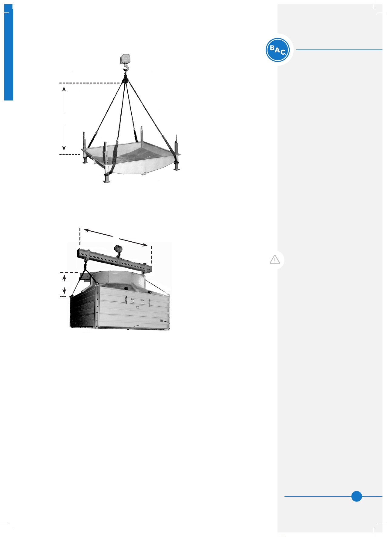
WARNING: Failure to use
designated lifting points
can result in a dropped load
causing severe injury, death,
and/or property damage.
Lifts must be performed by
qualied riggers following BAC
published Rigging Instructions
and generally accepted
lifting practices. The use of
supplemental safety slings
may also be required if the
lift circumstances warrant
its use, as determined by the
rigging contractor.
WARNING: This equipment has
the potential to be a high risk
hazard! Do not handle, rig,
lift, install, assemble, operate,
maintain or enter this
equipment without assessing
the risks involved. control
measures must be developed
to eliminate or minimise the
potential risks.
Sheaves and Belts
Bearings
Bearing Supports
Fan Motor(s)
Fan Guard(s)
Fan(s) and Fan Shaft(s)
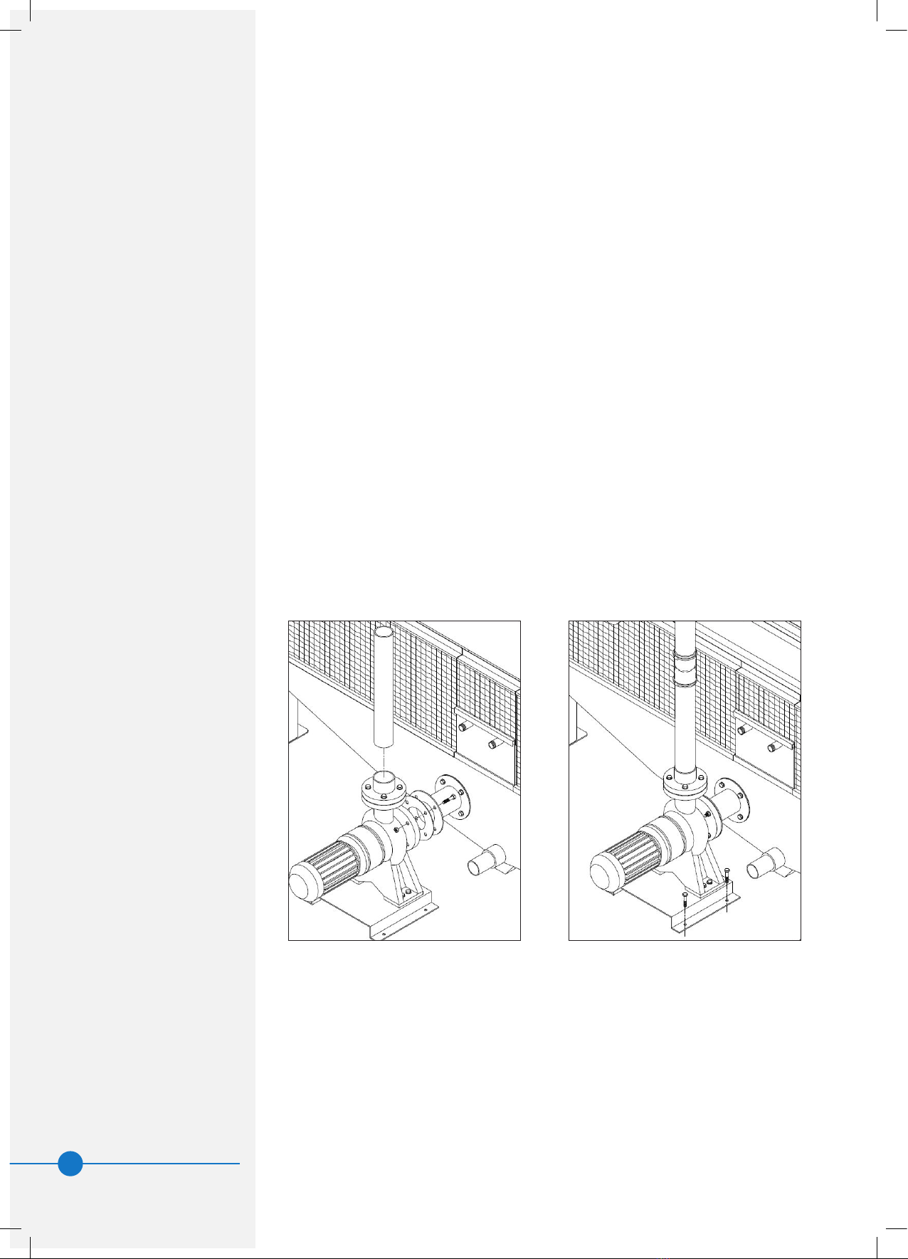
Float Valve Assembly(s)
Fill
Water Distribution System
Cold Water Basin Accessories
Interior Surfaces
Exterior Surfaces
Louvres
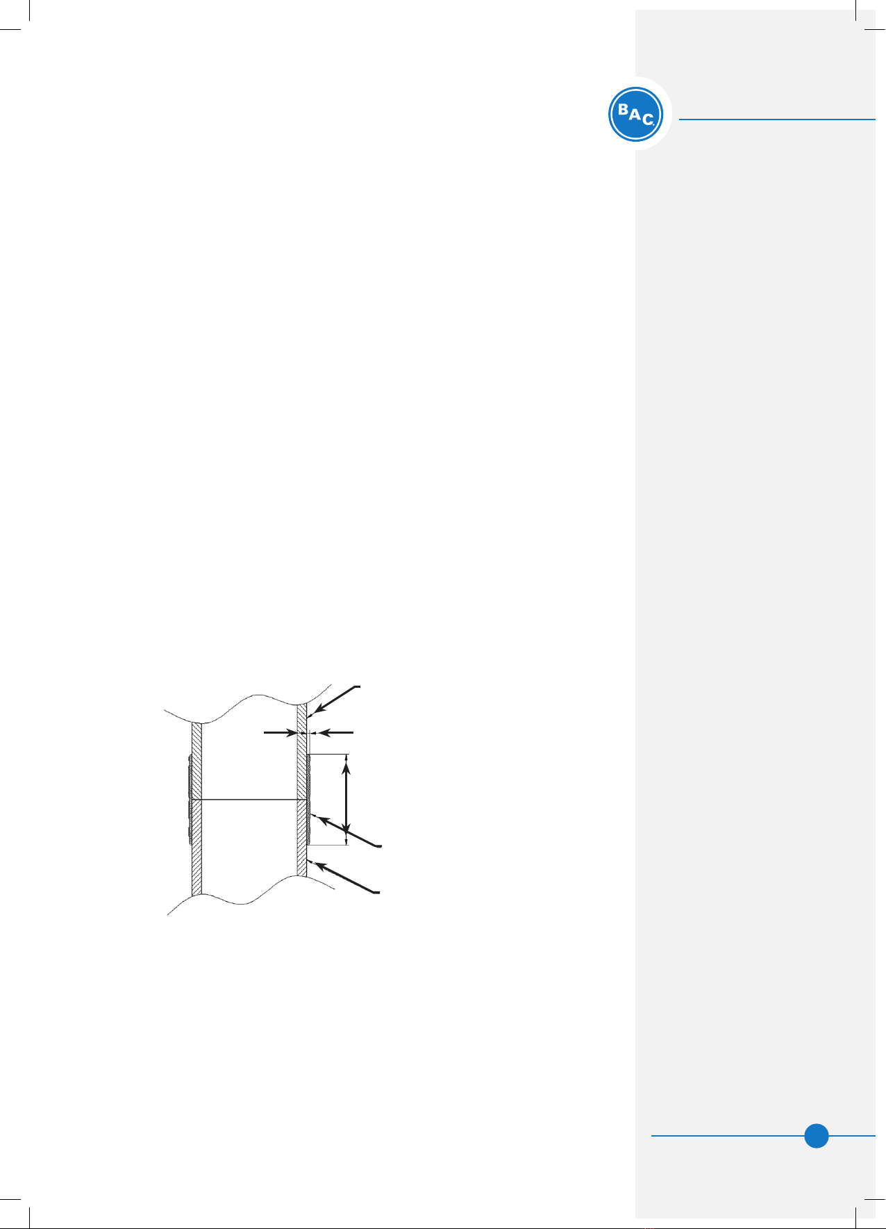
Mating Surfaces Between
Sections/Modules
Miscellaneous Items:
All bolts, nuts, washers,
and sealer tape required
to assemble sections
or component parts are
furnished by BAC and
shipped with the unit.
A checklist inside the
envelope marked “Customer
Information Packet”
indicates what miscellaneous
parts are included with the
shipment and where they are
packed. This envelope will
be attached to the side of
the unit or located in a box
inside the unit.

WWW.BALTIMOREAIRCOIL.COM.AU
3
MAR208-0
Introduction
Safety
Shipping
Pre-Rigging Checks
Unit Weights
Anchoring
Cold Weather Operation
Location
Warranties
Unit Operation
Unit Weights
Before rigging any unit, the weight of each section should be veried
from the unit submittal drawing. Unit print weights include the nal
assembled tower with all accessories.
Anchoring
Holes suited for M16 bolts are provided for bolting the unit to the
support beams. Refer to the suggested support drawing included in
the submittal for location and quantity of the mounting holes. The unit
must be level for proper operation. Anchor bolts must be provided by
others.
Support beams must also be level. Each footing should be shimmed
with a rm material to ensure the weight of the tower is carried at all
points and that the basin ledges are level at all places. Shims may be
required either side of a joint. This is to be done before the basin is
lled with water. If vibration isolators are used, a supporting framework
must be provided between the unit and the vibration isolators to
provide continuous and rigid support. Anchor bolts, footings and beams
to be supplied by others.
Cold Weather Operation
These products must be protected by mechanical and operational
methods against damage and/or reduced effectiveness during sub-
freezing temperatures. Please contact your local BAC Representative
for recommended cold weather operation strategies.
Location
All evaporative cooling equipment must be located to ensure an
adequate supply of fresh air to the fans. When units are located
adjacent to walls or in enclosures, care must be taken to ensure
that the warm saturated discharge air is not deected and short-
circuited back to the air intake(s). Also each unit should be located
and positioned to prevent the introduction of discharge air into the
ventilation system of the building on which the unit is located & of
adjacent buildings. For detailed recommendations on layouts, please
consult your local Baltimore Aircoil Representative.
Warranties
Please refer to the Limitation of Warranties (located in the submittal
package) applicable to and in effect at the time of the sale/purchase of
these products.
Unit Operation
Prior to start-up and unit operation, refer to the RC Series Operation &
Maintenance Manual shipped with the unit.
ATTENTION: Before an actual
lift is undertaken, ensure no
water, snow, ice, or debris
has collected in the basin
or elsewhere in the unit.
Such accumulations will
add substantially to the
equipment’s lifting weight.
WARNING: Drawing weights
are approximate only. They
should be conrmed by
weighing, before lifting, when
available hoisting capacity
provides little margin for
safety. Also before lifting
ensure that no water, ice, snow
or other debris has collected in
the unit. Such accumulations
will add substantially to the
equipment’s lifting weight.

WWW.BALTIMOREAIRCOIL.COM.AU
4
MAR208-0
2RC SERIES
Unit Rigging & Assembly
NOTE: For weight information,
refer to the submittal drawing
package.
NOTE: Any motors or
accessories shipped in the
cold water basin must be
removed prior to installation.
Rigging
To simplify shipping, rigging and installation all RC Series coil products
are shipped in major sections consisting of a basin assembly(s) and one
or more casing/roof deck sections (see Table 1).
The proper rigging sequence for the RC series is to lift the basin
section(s) into place rst. On multi-section basins lift each section into
place separately and then bolt sections together. Next, lift each casing
section into place and secure to the basin section. If motor(s) are
supplied loose t the motors. At the completion of this stage a crane is
no longer required.
Finally securely bolt the unit to supporting steel and on multi-section
basins seal the joint between sections.
Table 1 gives the recommended dimensions for rigging each section
of any RC series coil product. With the information from the table and
the additional instructions on the following pages the rigging of an RC
series coil product can be quickly accomplished.
Table 1. Recommended Dimensions for Rigging
NOMINAL
BOX
SIZES
No. of H1 H2 L
Basin Casing (g 1) (g 2) (g 2)
Sections (mm) (mm) (mm)
SINGLE FAN UNITS
5’ x 5’
1 each
1200 1700 1500
6’ x 6’ 1600 1900 1800
7’ x 7’ 1900 2200 2100
8’ x 8’ 2200 2500 2400
7’ x 10.5’ 2900 2200 3300
9’ x 9’ 2400 2700 2800
8’ x 12’ 3500 2500 3700
10’ x 10’ 2700 3000 3000
11’ x 11’ 2900 3300 3400
9’ x 13.5’ 4000 2700 4200
10’ x 15’ 4500 3000 4700
11’ x 16.5’ 5000 3300 5100
*** Casing Section Includes Roof Deck (Fan Assembly) ***

WWW.BALTIMOREAIRCOIL.COM.AU
5
MAR208-0
Section Assembly
1. Remove any motors or accessories shipped in the cold water basin.
2. Figures 1 and 2 show the proper rigging of the sections for units
that ship in two sections. Position the lower section on the steel
support and bolt in place.
3. Using basin to casing joining brackets, guide the upper section
onto the lower section. Match marks must line up.
4. Fasten the hardware between the upper casing and lower section
per Figure 3a, Page 6 (for HDG & SST coils) and 3b, Page 6 (for
copper coils).
WARNING: Unless units ship
fully assembled, basin &
casing/roof deck sections
must be rigged separately.
Never assemble the unit
before lifting as the lifting
devices provided on the
unit are not designed to
support the weight of the
entire assembled unit.
THE USE OF SAFETY
SLINGS IS RECOMMENDED
FOR EXTENDED LIFTS OR
WHENEVER HAZARDS EXIST.
Figure 1. Lifting basin section
H1
Figure 2. Lifting casing/roofdeck section
H2
L
Unit Rigging & Assembly
Rigging
Section Assembly

WWW.BALTIMOREAIRCOIL.COM.AU
6
MAR208-0
Figure 3a. Joining Casing to Basin section (HDG & SST coils)
Figure 3b. Joining Casing to Basin section (copper coils)

WWW.BALTIMOREAIRCOIL.COM.AU
7
MAR208-0
Field Sealing Of Basin To Casing Post Joint
(copper coils only)
Procedure:
1. Clean area for 30mm either side of the joint. Total width 60mm.
Use emery paper to rough up surface and remove sheen. Wipe with
acetone and allow to dry.
2. Wrap a layer of masking tape around post 30mm below joint and
a layer 30mm above the joint. This will assist in limiting spread of
excess sealer beyond sealing area.
3. Apply enough sealer on all faces of the square posts to give 2mm
thick coverage 30mm either side of the joint. Use a scraper to
spread this evenly over the surface. The sealer has a working time
of 30 minutes before skinning over.
4. Wrap berglass cloth over the joint and press into the sealer. Cloth
provided should wrap around the post approximately three times.
5. Apply and spread extra sealer if required to ensure berglass cloth
is coated with sealer.
6. Remove masking tape applied at step (2) and tidy up edges with
a scraper.
Figure 4. Sealing of Basin to Casing Post Joint
Basin Post
Easytape & Sealer
Casing Post
2 Min
60
Unit Rigging & Assembly
Field Sealing of Basin to Casing
Post Joint

WWW.BALTIMOREAIRCOIL.COM.AU
8
MAR208-0
Fitting Of Pump And Piping
To prevent transport damage the recirculation pump and lower piping
is removed from the unit at the factory prior to shipping and shipped
loose. Once the basin has been bolted down, the pump can then be
reinstalled as per the following steps:
1. Place the pump on the supporting structure and shim the pump
support base if required to align the pump suction with the unit
outlet connection.
2. Using the hardware and gasket provided fasten the pump to the
connection.
3. Fasten the pump base to the supporting structure using M16
hardware (supplied by others).
4. Once the pump is in place and secured, t the riser pipe to the
pump discharge ange using PVC pipe cement solvent.
5. Once the casing has been installed, the ends of the upper and
lower riser pipe sections should now be close together. Use the
rubber sleeve and hose clamps provided to join the two riser
sections (see Fig. 5b).
Figure 5a. Fitting Pump to Basin Figure 5b. Joining the Riser Pipe

WWW.BALTIMOREAIRCOIL.COM.AU
9
MAR208-0
Unit Rigging & Assembly
Fitting of Pump and Piping
Roof Deck Section Lifting
In certain situations it may be required that the roof deck section be
shipped separate to the casing. In this situation lifting of the roof
deck section will be required on site to position it back on the casing.
Where units are shipped in this orientation, extra lifting ears are
added to the roof deck.
The sketch below shows the orientation of each lifting ear as it bolts
to the joining ange between segments. For direct drives one lifting
ear per roof deck ange joint will be tted. In the eld, for belt drives
the lifting will take place with one sling around the motor and three
slings to the lifting ears. For this reason, the lifting ears are only
tted to the three anges not covered by the motor and mechanical
equipment support. These lifting ears are for use when lifting the
roof deck section only. They should not be used for lifting the entire
casing section.
Figure 6a. Lifting Lugs for Roof Decks
Figure 6b. Lifting Roof Decks
WARNING: UNDER NO
CIRCUMSTANCES SHOULD
THE ROOF DECK LIFTING
EARS BE USED FOR LIFTING
THE CASING SECTION. THEY
ARE ONLY DESIGNED FOR
LIFTING THE ROOF DECK.

WWW.BALTIMOREAIRCOIL.COM.AU
10
MAR208-0
Air Inlet Louvres
Air inlet louvres are a lift and drop in design. They are to be installed
with utes facing downwards into basin. A shorter louvre is provided to t
over the quick ll/makeup.
Float Valve
If the unit has shipped without the oat arm/ball assembly attached this
should be installed as per Figure 7, before louvres are installed.
Figure 7. Attaching oat arm
RC SERIES
Optional Accessory & Loose
Item Installation
3

WWW.BALTIMOREAIRCOIL.COM.AU
11
MAR208-0
RC SERIES
Optional Accessory & Loose
Item Installation
Fitting Tie Braces
Some RC series coil products are tted with tie braces on the basin
legs to provide structural stiffness to the unit. Where possible these
are factory tted although if they are shipped loose they will need to be
tted in the eld. The following procedure should be followed to t the
tie braces:
1. Once the basin has been levelled out and shimmed, and prior
to the casing being tted, an inspection should be made to
ensure that all posts are reasonably vertical and that the basin is
supported in all nine places [or twelve places for rectangular units].
2. Fit the diagonal tie braces at their top end only picking up pre-
drilled holes in the post. Do not drill the bottom tie brace holes
in the posts yet. The tie braces have a bend to give stiffness. The
bent edges should be oriented so that they will deect water into
the basin.
3. Place the casing on top of the basin legs with the majority of the
weight being carried by the crane. DO NOT REMOVE THE CRANE
UNTIL ALL TIE BRACES ARE TIGHTENED.
4. Check that posts are vertical and aligned correctly. The weight
of the casing and the position of the crane can skew the posts
sideways and may need adjustment. Swing the tie braces so that
the lower hole is centred in the basin post. If the posts are parallel
and square, the holes should be an equal distance up from basin
ledge. Once the posts are square, tie braces should be pulled tight
and clamped. The bolt holes may now be drilled and bolts tted.
Now tighten all tie brace bolts. The crane can now be released.
Figure 8. Fitting Tie Braces
Section AA
Optional Accessory &
Loose Item Installation
Air Inlet Louvres
Float Valve
Fitting Tie Braces

WWW.BALTIMOREAIRCOIL.COM.AU
12
MAR208-0
Fitting Of Wind Walls
1. Prior to tting ashing, the following steps in installation should have
taken place: (a) Basin(s) placed in position and shimmed to make level
and carry weight evenly. (b) Casing lowered onto basin legs and the leg
joiners bolted together.
2. With the casing bolted to the basin, seal the joints between the posts.
3. There are two ashing pieces provided for each side of the unit. Each
ashing piece rests on the berglass ledge of the basin wind wall. The
wind wall is not fully glued to the post and can be temporarily pulled
away from the post to slide the ashing in. Each ashing piece has
a folded end to prevent water falling out. When the ashing is in the
correct place, this folded end is sealing against the outside face of the
corner post. The ashing pieces overlap by approximately 30mm. They
are not designed to be bolted together.
4. To x the ashing in position, screw the Z-section brackets to the
ashing pieces so as to pull the ashing against the upper berglass
panel. Sealer is applied to the fastener as it is tted to prevent water
migration through the fastening points.
5. When the ashing is in place, there is a cavity created behind the corner
posts and sealing is required within this area. (a) Use the sealer provided
to seal the bottom horizontal corners behind the post. (b) Seal the
vertical joint between the post and ashing ends.
6. Seal the vertical joint where ashing pieces overlap each other.
7. It is not envisaged that sealing is needed on any of the other horizontal
joints such as where ashing overlaps berglass panels.
Figure 9. Fitting of Wind Walls

WWW.BALTIMOREAIRCOIL.COM.AU
13
MAR208-0
Optional Accessory
& Loose Item Installation
Fitting of Wind Walls
Piping
All piping must be supported external to the tower and restraint provided
to ensure no vertical or horizontal movement of the piping. All piping
and supports are to be furnished by others.
Fan Speed
When the fan speed of this product is to be changed from the factory
set speed, including the use of a variable fan speed control device, steps
must be taken to avoid operating at or near the fan’s “critical speed”
which could result in fan failure and possible injury or damage.
Bleed Line Installation
On all RC Series products install a bleed line with valve between the
system circulating pump discharge riser and a convenient drain. Locate the
bleed line in a portion of the riser piping that drains when the pump is off.
WARNING: The bleed valve
should always be open when
the unit is in operation,
unless the bleed rate is
automatically controlled by
a water treatment system.
Recommended bleed rates
may be found in the Operating
and Maintenance Manual or by
consulting a competent water
treatment specialist.

WWW.BALTIMOREAIRCOIL.COM.AU
14
MAR208-0
PLATFORM INSTALLATION
Factory Fitted Platforms
Where a platform is supplied with the unit it is normally tted to the casing
section at the factory. In this case only the ladder, stiles and landing need
to be tted on site. See gure 11a below demonstrating this.
Pre-Assembled Platforms Shipped Loose
In some instances due to transport limitations it is necessary to ship the
platform separate from the unit. In this case the platform must rst be
lifted up and xed to the platform support beam. See gure 11b below
demonstrating this. Once the platform is tted to the support beam the
ladder, stiles and landing can be tted as above.
Figure 11a.
Figure 11b.

WWW.BALTIMOREAIRCOIL.COM.AU
15
MAR208-0
Optional Accessory
& Loose Item Installation
Platform Installation
Factory Fitted Platforms
Pre-Assembled Platforms
Shipped Loose
Knock Down Platforms
Figure 11c.
Knock Down Platforms
Platforms may be shipped as a knock down kit for assembly on site if
required. If this is the case the platform must rst be assembled on the
oor before being lifted into place. Figure 11c below shows an exploded
view of a typical platform.

WWW.BALTIMOREAIRCOIL.COM.AU
16
MAR208-0
4RC SERIES
Final Assembly Details
Inspection
Prior to start-up, the following services, which are described in detail in
the RCC/RCF Operating and Maintenance Manual, must be performed:
- Inspect general condition of unit.
- Inspect fans, motors, bearings, drives, and belts for condition and
alignment.
- Lubricate all bearings and purge them of old grease.
- Check fans and air inlet areas for obstructions.
- Clean and ush basin, depressed sump and strainer.
- Inspect spray nozzles and heat transfer section.
- Check make-up valve and basin water level.
- Proper start up procedures and scheduled periodic maintenance
will prolong the life of the equipment and ensure the trouble-free
performance for which the unit is designed.
Piping (Process Water/Refrigerant)
All piping must be supported external to the tower and restraint
provided to ensure no vertical or horizontal movement of the piping. All
piping and supports are to be furnished by others.
Fan Speed
When the fan speed of this product is to be changed from the factory
set speed, including the use of a variable fan speed control device,
steps must be taken to avoid operating at or near the fan’s “critical
speed” which could result in fan failure and possible injury or damage.
Freeze Protection
This product must be protected by mechanical and operational
methods against damage and/or reduced effectiveness due to
possible freeze up. Please contact the local BAC Representative for
recommended protection alternatives.
WARNING: Do not run pump
unless basin is lled with water

WWW.BALTIMOREAIRCOIL.COM.AU
17
MAR208-0
Factory Assembly Details
Inspection
Piping
Fan Speed
Freeze Protection

COOLING TOWERS
CLOSED CIRCUIT COOLING TOWERS
ICE THERMAL STORAGE
EVAPORATIVE CONDENSERS
HYBRID PRODUCTS
PARTS & SERVICES
www.BaltimoreAircoil.com.au
120 Wisemans Ferry Road, Somersby NSW 2250 › Telephone (Australia): 1300.134.622 › Telephone (New Zealand): 0800.225.842
Other manuals for RC Series
1
Table of contents
Other BAC Industrial Equipment manuals
Popular Industrial Equipment manuals by other brands

MULTIQUIP
MULTIQUIP Whiteman series Operation and parts manual

SEW-Eurodrive
SEW-Eurodrive MAXOLUTION MAXO-MTS-T005-P-00-B04 operating instructions

ABB
ABB HT611114 Operation manual

Tempo Communications
Tempo Communications 920CL instruction manual

ABB
ABB HT579567 Operation manual

ProMinent
ProMinent Ultromat ULFa Series Assembly and operating instructions