BAC EASYBOND MK2 User manual

BAC Document Number: Easybond MK2 Manual V03
28/08/13
Page
1
of
32
P
IN BRAZING UNIT
O
PERATION AND MAINTENANCE MANUAL
PART NUMBER
273
199
5660
03 28/08/2013 LG SJ SFG For Issue
02 13/11/2012 LG SJ SFG For Issue
01 28/09/2011 SFG GL APG For Issue
00 27/05/2008 GS GS APG For Issue
Rev. Date Prepared By Checked By Approved By Status Remark
BAC Corrosion Control Ltd
Stafford Park 11, Telford, Shropshire, TF3 3AY
Tel: +44 (0) 1952 290321
Fax: +44 (0) 1952 290325
Email: sales@bacgroup.com

BAC Document Number: Easybond MKII Manual V03
28/08/13
Page
2
of
32
CONTENTS
1. INTRODUCTION .............................................................................................................4
2. SAFETY ..........................................................................................................................4
2.1
SYMBOLS
USED........................................................................................................................ 4
2.2
SAFETY
REGULATIONS ........................................................................................................... 5
2.3
GENERAL
SAFETY
WARNINGS ............................................................................................... 5
2.4
OPERATOR
COMPETENCY ..................................................................................................... 5
2.5
PERSONAL
PROTECTIVE
EQUIPMENT
(PPE)........................................................................ 5
3. GENERAL.......................................................................................................................6
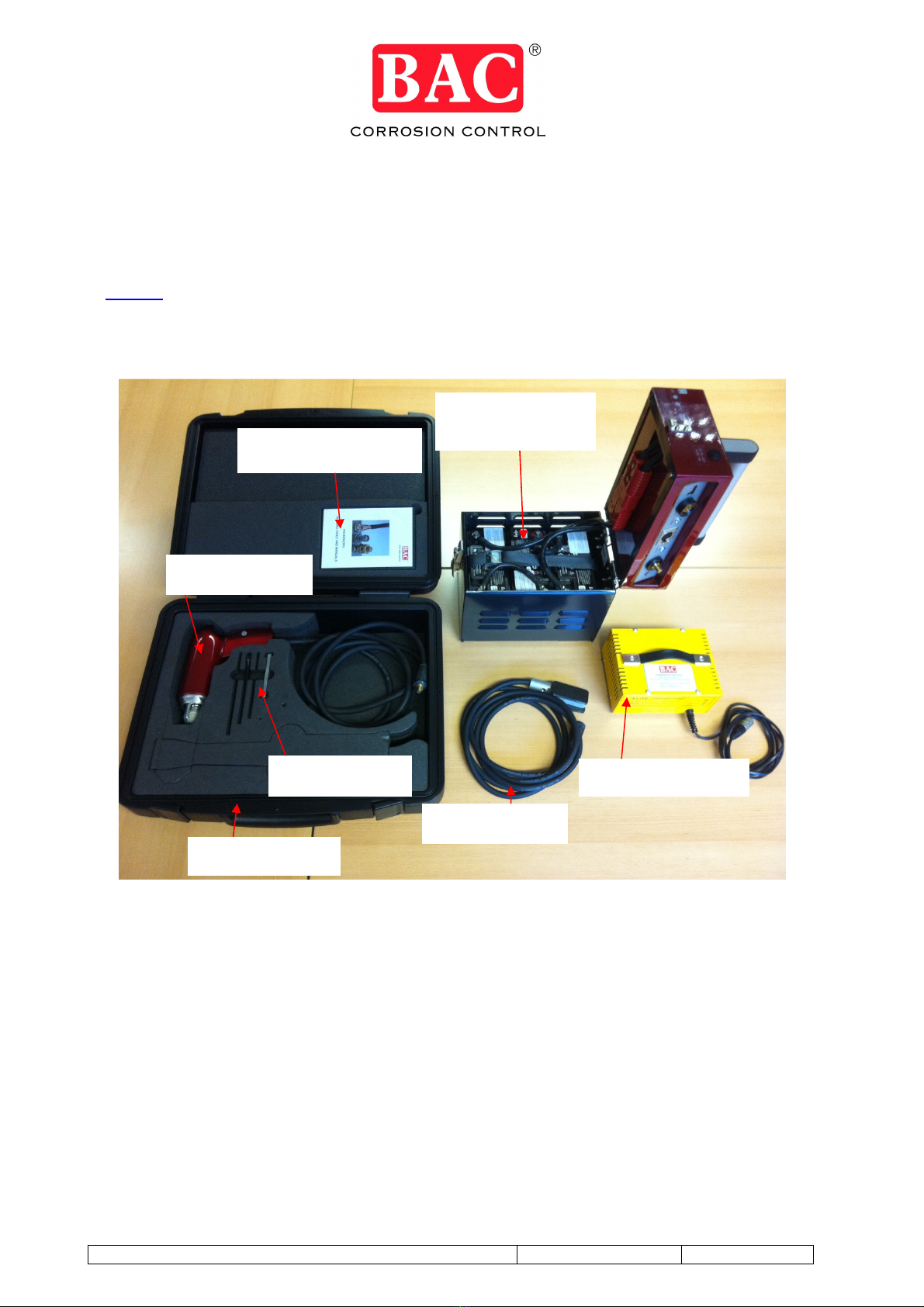
3.1
THE
EASYBOND
MKII
PIN
BRAZING
KIT
P
ART
#
273
199
5660 ............................................... 6
3.2
PART
NUMBERS
FOR
EASYBOND
MKII
PARTS..................................................................... 7
3.3
PACKING
DIMENSIONS............................................................................................................ 7
4. PIN
BRAZING .................................................................................................................8
4.1
THE
PIN
BRAZING
PROCESS .................................................................................................. 8
4.2
WET
WEATHER
USE................................................................................................................. 8
4.3
COLD
WEATHER
USE............................................................................................................... 8
4.4
PIN
BRAZING
CONSUMABLES
(B
RAZING
P
INS
,
C
ERAMIC
F
ERRULES AND
C
ABLE
L
UGS
)............. 8
4.5
STORAGE
OF
UNIT ................................................................................................................... 8
4.6
TRANSPORT
TO/FROM
SITE ................................................................................................... 8
5. INSTRUCTIONS
FOR
THE
PREPARATION
OF
THE
EASYBOND
FOR
OPERATION...9
5.1
CONNECTION
OF
THE
EASYBOND......................................................................................... 9
5.2
CONNECTION
OF
BATTERY
PACK........................................................................................ 10
5.3
ENERGY
(B
RAZE
/C
HARGE
)
MONITOR ..................................................................................... 10
6. PIN
BRAZING
CONSUMABLES...................................................................................11
7. OPERATION
OF
EASYBOND
PIN
BRAZING
UNIT ......................................................13
7.1
PREPARATION
OF
THE
SURFACE ........................................................................................ 13
7.2
LOADING
THE
PIN
INTO
THE
BRAZING
GUN........................................................................ 13
7.3
ADJUSTMENT
OF
BRAZING
GUN .......................................................................................... 14
7.4
LOCATION
OF
CONNECTIONS .............................................................................................. 15
7.5
PIN
BRAZING ........................................................................................................................... 15
7.6
TESTING
A
COMPLETED
BOND ............................................................................................ 17
8. FAULT
DIAGNOSIS
OF
UNSATISFACTORY
PIN
BRAZE
CONNECTION...................18
9. EQUIPMENT
CHECK....................................................................................................19
10. BATTERY
CHARGER...................................................................................................20
10.1
SAFETY .................................................................................................................................... 20
10.2
INSTRUCTIONS
FOR
USE ...................................................................................................... 21
10.3
LIGHT
SEQUENCE
INFORMATION: ......................................................................................... 21
10.4
BATTERY
CHARGER
TROUBLESHOOTING ......................................................................... 23
11. PIN
BRAZING
BATTERIES...........................................................................................24
11.1
QUICKCHANGE
RE-CHARGEABLE
BATTERY
PACK............................................................. 24
12. STANDARD
PIN
BRAZING
GUN
MAINTENANCE
MANUAL .......................................25
12.1
PARTS ...................................................................................................................................... 25
12.2
ROUTINE
MAINTENANCE....................................................................................................... 26
12.2.1
SERVICE SCHEDULE ......................................................................................................................... 26
12.2.2
REPLACEMENT OF THE CONTACT SET ............................................................................................ 26
12.2.3
REPLACEMENT OF CONTACT NIPPLE AND CERAMIC WASHER ....................................................... 27
12.3
TROUBLESHOOTING.............................................................................................................. 28

BAC Document Number: Easybond MKII Manual V03
28/08/13
Page
3
of
32
13. WEEE............................................................................................................................29
14. INSPECTION
AND
ACCEPTANCE
OF
PIN
BRAZING
EQUIPMENT
(GOODS) ...........29
15. WARRANTY .................................................................................................................29
15.1
WARRANTY
FOR
PIN
BRAZING
BATTERIES ........................................................................ 30
NOTES ......................................................................................................................................31

BAC Document Number: Easybond MKII Manual V03
28/08/13
Page
4
of
32
EASYBOND MKII PIN BRAZING UNIT
1. INTRODUCTION
Thank you for choosing the Easybond MKII Pin Brazing Unit, if operated and maintained as
recommended your Easybond MKII should give you many years of reliable use.
Pin brazing is an easy, metallurgically safe method of making electrical connections to steel and
ductile iron pipelines, as well as other metallic substrate that are to be cathodically protected,
electrically earthed or electrically bonded.
The Easybond MKII is designed for the onsite user who needs a portable, simple to use,
reliable, rugged and easily maintained machine to make electrical connections onto metallic
structures.
It is important that you carefully read and understand this manual and
take time to watch the training video supplied with your equipment prior
to operating the Easybond MKII equipment.
2. SAFETY
2.1 SYMBOLS USED
Read all manuals before using equipment
Wear overalls during operation
Wear safety boots during operation
An exposed surface is very hot and therefore dangerous
Wear safety gloves during operation
Wear eye protection during operation
Wear dust mask during operation
Wear ear defenders during operation
Observe the instructions in the text or graphic opposite
Worn out electrical products that should be sorted for recycling
Possible dangerous situation that could cause severe or fatal injury

BAC Document Number: Easybond MKII Manual V03
28/08/13
Page
5
of
32
2.2 SAFETY REGULATIONS
The safety of staff must be of prime consideration every time that pin brazing work is
carried out on the site and a full and comprehensive risk assessment must be
completed prior to any pin brazing being undertaken. Pin brazing operators must
comply with all current safety legislation and the specific safety requirements
procedures of the site and plant owners.
2.3 GENERAL SAFETY WARNINGS
Under no circumstances should the pin brazing equipment and its accessories be operated in
explosive atmospheres, such as in the presence of flammable liquids, gases, or dust. The
equipment will create sparks that may ignite dust or fumes.
Always ensure that the equipment is well maintained and never make any modifications to the
equipment or use spare parts and consumables not manufactured or recommended by BAC.
Never operate the equipment when tired, after drinking alcohol, taking drugs, or taking
medication that may make you drowsy.
Never operate the AC battery charger outside and in wet conditions.
Keep bystanders away whilst operating the equipment.
Do not abuse the cables and connectors and never use the cables for carrying or pulling the
equipment. Always use the optional extension cables when required.
2.4 OPERATOR COMPETENCY
It is highly recommended that operatives undertaking pin brazing for any form of attachment
should have attended a BAC approved training course in the pin brazing technique and hold a
current certificate of competency.
2.5 PERSONAL PROTECTIVE EQUIPMENT (PPE)
The following personal protective equipment is recommended whilst using the Easybond
equipment:
Overalls – conforming to EN ISO 11612:2008 or equivalent.
Safety Footwear – conforming to EN ISO 20345: 2011 S3 or equivalent.
Protective Gloves - conforming to EN12477:2001/A1:2005 Type B or equivalent.
Eye Protection - conforming to EN175:1997/166:1995/169:1992 or equivalent.
Dust/Fume respirator – conforming to FFP3 to EN149:2001 or equivalent.
Note: that when using the optional 18V grinder (part #273 199 0685) you must carefully read
the specific instruction manuals for this equipment. The manuals detail the safe operation of the
equipment and the PPE required during their use.

BAC Document Number: Easybond MKII Manual V03
28/08/13
Page
6
of
32
3. GENERAL
3.1 THE EASYBOND MKII PIN BRAZING KIT Part # 273 199 5660
The standard Easybond MKII system part # 273 199 5660 is comprised of components detailed
in figure 1.
When you receive your Easybond MKII unit check that you have the following:-
Figure 1
1. Power control unit
with battery pack
Part # 273 199 5610
6. Tool kit
Part # 273 190 0610
2. Brazing gun
Part # 273 199 0780
4. BAC battery charger
Part # 273 199 5020
3. Earth device
Part # 273 190 1360
5. Attaché case
Part # 273 190 4680
7. Manuals on CD
Part # 278 900 1900

BAC Document Number: Easybond MKII Manual V03
28/08/13
Page
7
of
32
3.2 PART NUMBERS FOR EASYBOND MKII PARTS
Description
Part #
Weight
Easybond MKII System Complete
273 199 5660
31.9 kg
1. Easybond MKII power control unit * 273 199 5610 21.0 kg
2. Standard gun * 273 199 0780 3.5 kg
3. Earth device * 273 199 1360 1.1 kg
4. BAC Pin brazing battery charger * 273 199 5020 3.0 kg
5. Attaché case * 273 190 4680 3.3 kg
6. Tool kit * 273 190 0610 0.3 kg
7. Manuals on CD * 278 900 1900
Easybond MKII Power
Control Unit
273 199 5610
21.0 kg
Battery kit (web and 3 x batteries) ** 273 199 5630 15.3 kg
Pin brazing enclosure ** 273 199 5690 5.7 kg
Re
-
c
hargable
b
attery
p
ack
with charge adaptor
273 199 5640
15.8 kg
Battery kit (web and 3 x batteries) *** 273 199 5630 15.3 kg
Charge adaptor *** 273 199 5620 0.5 kg
Optional accessories
Grinder with 2 x 18V batteries 273 199 0685 5.8 kg
Grinding burr 273 190 1370 0.04 kg
In car battery charger VEPAC 273 199 5040 1.5 kg
Extension cable 2.5m 273 190 1460 1.3 kg
Portable trolley 273 100 4825 6.5 kg
* Included when purchasing part number 273 199 5660.
** Included when purchasing part number 273 199 5610.
*** Included when purchasing part number 273 199 5640.
3.3 PACKING DIMENSIONS
Power control unit: 380mm x 320mm x 420mm
Attaché case: 540mm x 320mm x 160mm
Battery charger: 230mm x 200mm x 120mm
18V grinder case: 470mm x 310mm x 170mm

BAC Document Number: Easybond MKII Manual V03
28/08/13
Page
8
of
32
4. PIN BRAZING
4.1 THE PIN BRAZING PROCESS
The Easybond MKII is powered by a 36V battery pack capable of delivering 240A (ampere) for
use with BAC fused brazing pins, ceramic ferrules and cable lugs.
The pin brazing process is initiated by depressing a trigger on the pin brazing gun. The circuit is
completed via the magnet attachment to the substrate through which a DC current is passed.
The brazing pin tip is the point of highest resistance at which point an arc is drawn, melting the
solder whilst simultaneously heating the cable lug material and the surface of the structure to
the required soldering temperature.
After approximately 1.5 seconds the circuit is mechanically broken as the fuse wire breaks, the
solenoid is de-energised and the brazing pin is held into the molten pool of brazing alloy. The
brazing pin tip, alloy, flux and cable lug (if used) rapidly cool into a homogenous unit achieving a
very strong connection onto the substrate.
4.2 WET WEATHER USE
Pin brazing attachments can be successfully made to wet metal and in mildly inclement
weather, i.e. light rain, drizzle or snow.
However, heavy rain may cause the pin fuse wire to burn out prematurely resulting in no bond
being made.
4.3 COLD WEATHER USE
It is possible to undertake pin brazing attachments to metals at sub-zero temperatures.
However, the efficiency of the batteries will be reduced in colder weather. Therefore, where
practicable, shield the battery pack from extreme cold.
4.4 PIN BRAZING CONSUMABLES (Brazing Pins, Ceramic Ferrules and Cable Lugs)
The Easybond MKII Pin Brazing unit uses BAC fused pins to make the electrical connections.
Each brazing pin is tipped with low temperature brazing alloy and the correct amount of flux,
and has attached a copper fuse wire at the other end, which acts as a timed circuit breaker to
control the duration of the braze. Refer to section 6.
4.5 STORAGE OF UNIT
The unit is to be stored in any dry room or cabinet where a constant power supply to the battery
charger can be made available.
There must be adequate ventilation at all times to prevent possible build up of gas evolved from
the batteries during charging.
It is recommended that the batteries be stored at an ambient temperature of 25°C (77°F)
4.6 TRANSPORT TO/FROM SITE
The unit can be transported safely in the rear of a vehicle when secured to prevent movement.
The unit can also be supplied with an optional trolley that can be used to transport the pin
brazing unit around site.

BAC Document Number: Easybond MKII Manual V03
28/08/13
Page
9
of
32
5. INSTRUCTIONS FOR THE PREPARATION OF THE EASYBOND FOR OPERATION
5.1 CONNECTION OF THE EASYBOND
The various components of the Easybond MKII are connected as detailed in figure 2.
Figure 2
Item
Description
1
Fuse
15
A
(Part #
010 011 0782)
2
Brazing
g
un plug socket
3
Energy
m
onitor
s
ystem
-
Charge
LED
r
ed (
l
ow battery warning)
4
DC
s
ocket for 42V grinder
or
battery charger
5
Energy
m
onitor
s
ystem
-
Braze LED blue (
OK to
b
raze indicator)
6
Socket for
e
arth
device
7
Brazing
g
un
(Part #
273 199 0780)
8
Earth
device
(Part # 273 190 1360)
9
Power
c
ontrol
u
nit with
b
attery
p
ack
(Part # 273 199 5610)
10
*
42V
Grinder
Part # 273 199 0680 (no longer in production)
1
1
BAC b
attery
c
harger
(mains)
(Part # 273 199 5020)
or
In
c
ar
b
attery
charger VEPAC (Part # 273 199 5040)
* This item has been replaced with a standalone 18V battery operated die
grinder (Part #273 199 0685)

BAC Document Number: Easybond MKII Manual V03
28/08/13
Page
10
of
32
5.2 CONNECTION OF BATTERY PACK
On receipt of your Easybond MKII you will need to fully recharge the battery pack.
Due to possible lengthy shipping times and unavoidable temperature shifts during
transportation, the power control unit will arrive with the battery pack disconnected. Before using
the equipment for the first time the battery connector must be connected and the power control
unit put on charge until the battery pack is fully charged.
To reconnect the battery pack open the lid of the power control unit (figure 2 -9), accessible by
undoing the safety latch, and connect the red male and female plugs that are located on the
power control unit lid.
The battery pack should then be fully charged using only the recommended battery chargers.
The unit should then remain on trickle charge for at least 24 hours before normal use can
commence. Refer to section 10.2 battery charger
WHEN BATTERIES ARE ON CHARGE ALWAYS LEAVE THE POWER
UNIT BOX LID IN THE OPEN POSITION.
NO SMOKING OR NAKED FLAMES AS EXPLOSIVE GASES MAY BE EVOLVED.
5.3 ENERGY (Braze/Charge) MONITOR
The Energy Monitor System constantly checks the battery condition and is able to
assess whether there is sufficient power available for optimum braze results and safe use of the
equipment.
Recovery mode - The red LED flashes when the voltage drops below 36.30V. This occurs
during brazing and whilst the batteries are recovering.
Re-charge mode - The red LED will permanently illuminate when the unit has remained below
36.30V for a period indicating that battery recovery time (approximately 10 seconds) has been
insufficient and requires fully re-charging.
System ready - The blue LED signals the system is safe to be used (36.40V+).
System standby - Represented when both red and blue LED’s are off, this indicates that the
voltage is below that which is required for safe use of the equipment but battery recovery is
imminent (36.30-36.39V). Once recovered the blue LED will illuminate. If a brazing operation is
attempted whilst the unit is in Standby then the red LED will permanently illuminate to indicate
the system must be fully re-charged.
Once the battery charger is attached directly to the Easybond MKII it is possible that the
blue LED will immediately illuminate. This however does not indicate that the system is
now ready for safe use. Whilst on charge the battery status must ONLY be monitored via
the LED’s on the battery charger unit. See section 10, Battery charger.
Do not attempt to braze when the unit is in standby, recovery or re-charge
mode.

BAC Document Number: Easybond MKII Manual V03
28/08/13
Page
11
of
32
6. PIN BRAZING CONSUMABLES
Easybond MKII consumables are available as direct pins for attachment of pin brazing cable
lugs and threaded pins
of
various sizes. All Easybond MKII pins have a fuse wire.
BRAZING PINS
Brazing pins are available in direct connection or threaded formats of various sizes. The pins
must be kept dry, stored in delivery tins and care must be taken not to mix different part
numbers.
CABLE LUGS
BAC cable lugs are specially manufactured in the intended material for pin brazing. The lugs are
made in three different types. M1 is pin brazed to the cable. M2 is crimped to the cable and the
“stinger” is pin brazed with the cable. The “stinger” permanently connects anode wires with a
small diameter to pipes utilising the unique silver alloy BAC pin brazing method, without the use
of cable lugs, crimping or old exothermic reactions. The lugs must be kept dry, stored in delivery
tins and care must be taken not to mix different part numbers.
Always use BAC approved crimping methods to ensure adequate contact.
CERAMIC FERRULES
A new ferrule must always be employed in pin brazing (the ferrule must be changed after each
brazing operation). The purpose of the ferrule is to prevent splattering of the molten solder, to
prevent oxidation of the molten solder, and to protect the operator against radiation from the arc.
The ferrule must be kept dry, stored in delivery tins and care must be taken not to mix different
part numbers.
REDUCING SLEEVES
Sleeves are manufactured to allow smaller cables to be crimped into larger than usual lugs. The
cable is inserted into the sleeve, then the sleeve and cable are inserted into the lug. All three
items are then crimped together.
If you are offered any pin brazing consumables from sources other than
from BAC directly or a local BAC appointed Distributor/Agent then we
strongly advise that you do not use those consumables with BAC pin
brazing equipment to avoid any serious risk to people, pipelines and BAC pin brazing
equipment. If in doubt contact BAC.
All BAC products are manufactured to the highest standards under our ISO 9001:2008
procedures. If the use of non BAC pin brazing products and consumables is evident then
warranties will be void. All BAC pin brazing supplies now carry the following notice:

BAC Document Number: Easybond MKII Manual V03
28/08/13
Page
12
of
32
Figure 3
Failure to store consumables correctly can result in defective bonding work.
Item Part # Description DIMS Pack Size
1 278 190 3250 8 mm direct brazing pin ∅8 mm 100
1 270 083 3520 Direct brazing pin, extra solder
∅8 mm 100
4 270 065 7230 Ceramic ferrule for direct pin ∅8 mm 100
2 278 190 0430 M8 Threaded brazing pin 12 x 30 mm 50
(includes nuts and washer)
3 278 190 3450 M10 Threaded brazing pin 12 x 34 mm 40
(includes nuts and washer)
3 278 190 2560 M12 Threaded brazing pin 12 x 34 mm 40
(includes nuts and washer)
4 270 077 3680 Ceramic ferrule for threaded pin
∅12 mm 50
5 278 100 7360 M2 Cable lug 10 mm
2
cable 6 x 9 mm 100
5 278 100 9000 M2 Cable lug 16 mm
2
cable 6 x 9 mm 100
6 270 088 7800 M2 Cable lug 25 mm
2
cable 8 x 12 mm 50
6 278 100 7810 M2 Cable lug 35 mm
2
cable 9 x 13 mm 50
6 270 088 7790 M2 Cable lug 50 mm
2
cable 11 x 14 mm 50
8 278 100 8012 Stinger #12AWG (1 - 2.5mm
2
) ∅17 x 3 mm
100
8 278 100 8042 Stinger #10AWG (4 - 6mm
2
) ∅17 x 5 mm
100
278 100 8050 Stinger #12AWG kit
(includes stinger
(278 100 8012)
, brazing pin
(278 190 3250)
& ferrule
(270 065 7230)
)
50
278 100 8060 Stinger #10AWG kit
(includes stinger
(278 100 8042)
, brazing pin
(278 190 3250)
& ferrule
(270 065 7230)
)
50
5
M2
6
M2
7
M1
8
1
2
3
4

BAC Document Number: Easybond MKII Manual V03
28/08/13
Page
13
of
32
7. OPERATION OF EASYBOND PIN BRAZING UNIT
7.1 PREPARATION OF THE SURFACE
It is crucial that to achieve a successful pin braze, the area of connection onto the pipeline
(or other metal substrate) has a clean bright metal finish. In order to achieve this some
degree of surface preparation will be required.
Pipeline and plant owners often have their own procedures for surface preparation and
you should fully familiarise yourself with these procedures prior to any surface preparation
works.
STEP ONE
Figure 4
If necessary, the surface encompassing the pin braze area and adjacent earth connection shall
be degreased before any grinding operation.
Scrape and clean the steel and clean an area for the earth device as near as possible to the
braze area as illustrated in STEP ONE - figure 4.
The metal surface must then be prepared to a bright clean finish to ensure a sound electrical
connection between the earth device and the substrate. Never continuously work the metal such
that any wall thickness is reduced.
An area sufficient to accommodate the brazing pin and cable lug must be correctly located and
cleaned to a bright metal finish.
To prevent the cleaned metal surface re-oxidising, we recommend that pin brazing must take
place as soon as possible after surface preparation, i.e. not more than 5 minutes delay.
Note that when using the optional 18V grinder (part #273 199 0685) you must carefully
read the specific instruction manuals for this equipment. The manuals detail the safe
operation of the equipment and the PPE required during their use.
7.2 LOADING THE PIN INTO THE BRAZING GUN
Load the gun with a brazing pin and ceramic ferrule individually by hand. Ensure that they are
both back fully inserted and tight with the palm of your hand, as illustrated in STEP TWO –
figure 5.

BAC Document Number: Easybond MKII Manual V03
28/08/13
Page
14
of
32
STEP TWO
Figure 5
DO NOT STRAIGHTEN THE KINKED END OF THE PIN FUSE WIRE.
The legs of the pin holder must be adjusted as necessary to ensure a firm grip of the pin while
maintaining concentricity with the ferrule holder.
Important:
Under no circumstances should a brazing pin which has been inserted and then
removed from the gun be re-inserted and used for brazing without checking the kinked
end profile and fuse wire connection to pin.
7.3 ADJUSTMENT OF BRAZING GUN
Before connecting the earth device to the steel, adjust the brazing pin "Lift Height" as
follows:
Hold the cable lug or stinger flat on the steel surface (for direct pin connection). Insert a loaded
brazing pin into the hole in the lug and press the gun/ferrule against the surface of the lug
evenly overcoming the internal spring. Turn the ferrule holder until the white adjustment
indicator tube is flush with the gun's rear face. The brazing gun should now be correctly set, as
illustrated in STEP THREE – figure 6.
When using threaded brazing pins, i.e. M8 brazing pin, the ceramic ferrule must be flat against
the steel surface when checking the white adjustment indicator tube.
STEP THREE
Figure 6

BAC Document Number: Easybond MKII Manual V03
28/08/13
Page
15
of
32
7.4 LOCATION OF CONNECTIONS
The desired position of the required pin braze area should be accurately marked on the steel.
Do not use any oil based marker e.g. spray paint, as this will contaminate the grinding burr.
When pin brazing onto a coated pipeline then sufficient coating needs to be removed in order to
accommodate both the earth device and area of the pin braze, this would be a minimum of 14
cm x 4 cm using the standard earth device. If the earth device is placed on a separate earth
point on the pipe then the area required at the pin braze point will be a minimum of 4 cm x 4 cm.
7.5 PIN BRAZING
STEP FOUR
Figure 7
1. The magnetic earth device must be applied to the cleaned surface to ensure a sound
electrical circuit.
2. The brazing gun must be correctly adjusted with the correct pin and ferrule fitted.
3. Locate the brazing pin so that the pin is in the centre of the hole in the cable lug. For vertical
surfaces, the pin must be at the upper part of the hole in the cable lug.
4. Apply sustained pressure on the brazing gun so that full contact is made between the ferrule
and the bond attachment (or the steel surface when using threaded pins).
5. When the operator is ready to braze, he should look well to one side to protect his eyes from
glare. The operator’s stance should be stable to enable this movement to be made without
altering the critical positioning of the gun.
6. Hold the gun firmly and close the circuit by squeezing the trigger.

BAC Document Number: Easybond MKII Manual V03
28/08/13
Page
16
of
32
KEEP THE TRIGGER DEPRESSED UNTIL THE BRAZE IS COMPLETE
7. After about 2 seconds the fuse wire should rupture, disconnecting the circuit. The arc will
extinguish and the pin or stud will be shot forward into the molten filler.
8. In the event of a fuse not rupturing after the normal time, the gun must be withdrawn
completely from the work, keeping the trigger depressed.
9. After the fuse has ruptured, the gun must be held in place for a further 3 seconds to allow
the braze to set
10. Remove the gun by pulling straight off the pipe or substrate in line with the brazed pin, then
break out the ferrule if this is remaining in the ferrule holder. This can be achieved by
levering against a suitable edge. Beware, it may be hot.
11. Hold the gun in a vertical position then depress the ejector button to expel the remaining
fuse wire. Catch the wire in your hand to ensure it has been ejected, as illustrated below in
figure 7(a).
Figure 7(a)

BAC Document Number: Easybond MKII Manual V03
28/08/13
Page
17
of
32
7.6 TESTING A COMPLETED BOND
Threaded pin attachments should be tested by a torque device. For an M8 pin the torque device
should be set to 10 Nm. The threads will fail at 25 Nm so do not use excessive force.
Direct braze pin attachments must be tested as per STEP FIVE – figure 8 as follows:
The shank of the plain pin must be carefully broken off with a hammer taking care not to
damage the lug. This must be done before another pin braze is made to the bond. After
breaking off the shank the broken surface should be level or thereabouts with the outer surface
of the lug (figure 9 [A]). The lug shall be complete in all aspects.
STEP FIVE
Figure 8
If the surface of the broken pin is proud of the surface of the lug this is an indication that the
brazing time was too short *(figure 9 [B]). The reason for a short braze time is usually the result
of excessive current being drawn due to the gun "lift height" being incorrect. This short time can
also be caused by a poor earth connection.
If the surface of the broken pin is below the surface of the lug, this is an indication that the
brazing time was too long (figure 9 [C]). The reason for a long braze time is the result of
insufficient current being drawn. Insufficient current is usually the result of a poor battery
condition.
If it is known that the battery is good then the cause may be incorrect setting of the gun "lift
height".
If the ferrule is not held against the copper lug and is in partial contact then the arc can escape
out of the gap and this will result in the side of the copper lug burning away.
Warning: Repeated bond attempts must not be made at the same position as this may
cause structural/metallurgical damage to the base steel.
* When using cable lugs part number #278 100 9000 /#278 100 7360 this result (figure 9
[B]) is acceptable due to thickness of copper material at braze area. Height of remaining
brass shank should not exceed 2mm.

BAC Document Number: Easybond MKII Manual V03
28/08/13
Page
18
of
32
8. FAULT DIAGNOSIS OF UNSATISFACTORY PIN BRAZE CONNECTION
Some common problems can be experienced by operators when first using the equipment.
Listed below are a series of faults together with the most likely cause and remedy solutions. In
the event of persistent problems or faults, contact the service engineer for advice or repair.
PROBLEM
POSSIBLE CAUSE
REMEDY
No arc or there is a short
“pop” of the pin
Circuit not complete or
highly resistive
Check fuse wire on pin is
engaged
Check earth device is connected
Batteries flat Charge/replace batteries
Arc time too short
Figure 9 (B)
Excessive current drawn
Poor earth connection
Check gun adjustment
Reset earth connection
Arc time too long
Figure 9 (C)
Insufficient current drawn Check gun adjustment
Recharge batteries
Bond falls off when
tested
Too short brazing time
Base metal not clean
enough
See above
Thoroughly clean the area to be
brazed
Fuse wire stuck in
contact nipple
Pin loose in holder
Failure to eject previous
fuse wire
Tighten fit of pin holder jaws
Replace contact nipple
Brazing pin fails to push
into molten braze
material
Pin is out of line from the
ferrule due to off centre
ferrule holder jaws
caused by heavy removal
of spent ferrule
Take care not to bend ferrule
holder jaws when removing
spent ferrule
Replace ferrule holder
A.
B.
C.
Figure 9

BAC Document Number: Easybond MKII Manual V03
28/08/13
Page
19
of
32
9. EQUIPMENT CHECK
When the equipment is in use, time must be allowed during a working period to carry out the
necessary checks and servicing required. Carrying out these procedures will prevent time
wasted on site, when work is aborted due to faulty equipment.
Time and personnel must also be allocated to the general servicing of equipment on a routine
basis. Refer to the maintenance manual in section 12 for more information.
If the servicing procedures set out in this instruction manual have been correctly carried out and
a problem still exists contact the sales department at BAC Corrosion Control for advice on +44
If it is necessary to return the equipment for repair, ensure that the complete pin brazing set,
including all ancillary equipment, is despatched to permit full functional testing.

BAC Document Number: Easybond MKII Manual V03
28/08/13
Page
20
of
32
10. BATTERY CHARGER
PART NUMBER 273 199 5020
Figure 10
The BAC pin brazing battery charger is a 36V 2A, eight-step charge microprocessor controlled
charger, designed to quickly and effectively restore discharged 36V sealed valve regulated lead
acid battery packs. The charger is specially optimised to be used with all BAC pin brazing units.
Light # (figure 10) Colour Condition
1. Red Mains On
2. Yellow Bulk Charge
3. Green Float / Standby
10.1 SAFETY
This appliance must be earthed and it is for AC input only - see rating label on charger for
details. It is for indoor use only - do not expose to rain or moisture.
Disconnect the AC mains supply before connecting or disconnecting the charger from the
battery.
If the AC power lead is damaged, this appliance should not be used.
If the plug supplied with this appliance is cut from the power supply cord so that another plug
can be fitted, it must be disposed of safely. If such a plug is inserted in a 13A socket outlet the
cut end of the cable would present a shock hazard.
If a 13A non-rewired plug is fitted to this appliance it must be fitted with a three amp (3A)
BS1362 fuse. The fuse cover supplied must be re-fitted if the fuse is changed. If the fuse cover
is lost, the plug must not be used until a replacement is obtained.
Batteries may emit explosive gas mixture - prevent flames and sparks.
Do not attempt to recharge non-rechargeable batteries, they may explode.
This manual suits for next models
1
Table of contents
Other BAC Industrial Equipment manuals
Popular Industrial Equipment manuals by other brands

Galiso
Galiso 21-11-1008 Assembly, installation and operation instructions

Nordson
Nordson Prodigy HDLV Pump Generation II Customer product manual

Nederman
Nederman ALU 150 user manual

Hindon
Hindon L Series manual

Siemens
Siemens 3VT9300-8LA00 operating instructions

Siemens
Siemens SINAMICS G110M Getting started