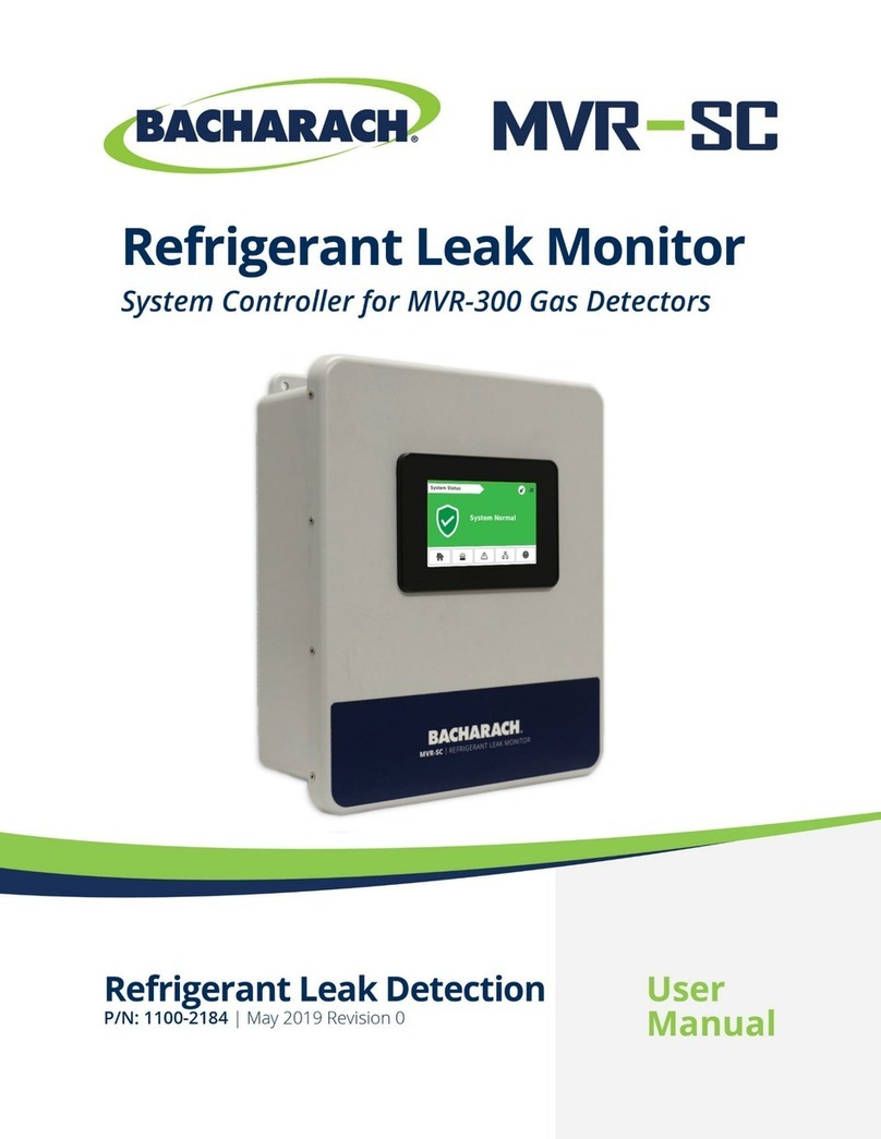
Bacharach MVR-SC User manual


MVR-SC™ Refrigerant Leak Monitor
2 1100-2184 Rev 1
WARRANTY POLICY
Bacharach, Inc. warrants to buyer that at the time of delivery this product will be free from defects in material and manufacture and will conform
substantially to Bacharach, Inc.’s applicable specifications. Bacharach’s liability and buyer’s remedy under this warranty are limited to the repair or
replacement, at Bacharach’s option, of this product or parts thereof returned to seller at the factory of manufacture and shown to Bacharach, Inc.’s
reasonable satisfaction to have been defective; provided that written notice of the defect shall have been given by buyer to Bacharach, Inc. within one
(1) year after the date of delivery of this product by Bacharach, Inc.
Bacharach, Inc. warrants to buyer that it will convey good title to this product. Bacharach’s liability and buyer’s remedy under this warranty of title are
limited to the removal of any title defects or, at the election of Bacharach, to the replacement of this product or parts thereof that are defective in title.
THE FOREGOING WARRANTIES ARE EXCLUSIVE AND ARE GIVEN AND ACCEPTED IN LIEU OF (I) ANY AND ALL OTHER WARRANTIES,
EXPRESS OR IMPLIED, INCLUDING WITHOUT LIMITATION THE IMPLIED WARRANTIES OF MERCHANTABILITY AND FITNESS FOR A
PARTICULAR PURPOSE: AND (II) ANY OBLIGATION, LIABILITY, RIGHT, CLAIM OR REMEDY IN CONTRACT OR TORT, WHETHER OR NOT
ARISING FROM BACHARACH’S NEGLIGENCE, ACTUAL OR IMPLIED. The remedies of the buyer shall be limited to those provided herein to the
exclusion of any and all other remedies including, without limitation incidental or consequential damages. No agreement varying or extending the
foregoing warranties, remedies or this limitation will be binding upon Bacharach, Inc. unless in writing, signed by a duly authorized officer of Bacharach.
Register Your Warranty by Visiting: www.mybacharach.com/warranty-registration/
SERVICE POLICY
Bacharach, Inc. maintains a service facility at the factory. Some Bacharach distributors / agents may also have repair facilities; however, Bacharach
assumes no liability for service performed by anyone other than Bacharach personnel. Repairs are warranted for 90-days after date of shipment
(sensors, pumps, filters and batteries have individual warranties). Should your analyzer require non-warranty repair, you may contact the distributor from
whom it was purchased or you may contact Bacharach directly.
If Bacharach is to do the repair work, send the controller, prepaid, to the closest service center. Prior to shipping equipment to Bacharach, visit
www.mybacharach.com for a Returned Merchandise Authorization Number (RMA #). All returned goods must be accompanied by a RMA #. Pack the
equipment securely (in its original packing, if possible), as Bacharach cannot be held responsible for any damage incurred during shipping to our facility.
Always include your RMA #, shipping address, and telephone number, contact name, billing information and a description of the defect as you perceive
it. You will be contacted with a cost estimate for expected repairs prior to the performance of any service work. For liability reasons, Bacharach has a
policy of performing all needed repairs to restore the controller to full operating condition.
NOTICES
Product improvements and enhancements are on-going, therefore the specifications and information contained in this document may change without
notice.
Bacharach, Inc. shall not be liable for errors contained herein or for incidental or consequential damages in connection with the furnishing, performance,
or use of this material.
No part of this document may be photocopied, reproduced, or translated to another language without the prior written consent of Bacharach, Inc.
Copyright © 2020, Bacharach, Inc., All Rights Reserved.
BACHARACH is a registered trademark of Bacharach, Inc. All other trademarks, trade names, service marks and logos referenced herein belong to their
respective companies.

MVR-SC™ Refrigerant Leak Monitor
1100-2184 Rev 1 3
Table of Contents
SECTION 1. INTRODUCTION 4
1.1 About this Manual............................................................................................................................................................................... 4
1.2 Iconography........................................................................................................................................................................................ 4
1.3 General Safety Statements................................................................................................................................................................. 4
SECTION 2. PRODUCT DESCRIPTION 5
2.1 Product Overview ............................................................................................................................................................................... 5
2.2 Design Features ................................................................................................................................................................................. 5
2.3 Bill of Materials ................................................................................................................................................................................... 5
2.4 Specifications ..................................................................................................................................................................................... 6
2.4.1 Hardware Specification.............................................................................................................................................................. 6
2.4.2 Network Specifications .............................................................................................................................................................. 6
2.5 Components ....................................................................................................................................................................................... 7
2.5.1 Network Components................................................................................................................................................................ 8
SECTION 3. NETWORK OVERVIEW 9
SECTION 4. INSTALLATION 10
4.1 Warnings & Cautions........................................................................................................................................................................ 10
4.2 Preliminary Inspection ...................................................................................................................................................................... 10
4.3 Suitable / Appropriate Locations....................................................................................................................................................... 10
4.4 Mounting Instructions........................................................................................................................................................................ 11
4.5 Electrical and Communications Wiring.............................................................................................................................................. 12
4.6 Relay Wiring ..................................................................................................................................................................................... 13
4.7 Connecting Modbus Gateways (1100-2198, MOXA MGate MB3170) .............................................................................................. 13
4.8 Connecting Ethernet Network Switches (1100-2172, MOXA EDS-208A) ......................................................................................... 14
4.9 Connecting MVR-300’s..................................................................................................................................................................... 15
SECTION 5. COMMISSIONING 16
5.1 System Overview.............................................................................................................................................................................. 16
5.2 Commissioning MVR-SC .................................................................................................................................................................. 19
5.2.1 Floorplan Spreadsheet ............................................................................................................................................................ 19
5.2.2 Floorplan Spreadsheet Setup.................................................................................................................................................. 20
5.2.3 Upload Floorplan ..................................................................................................................................................................... 20
5.2.4 System Time and Date ............................................................................................................................................................ 21
5.3 Commissioning MVR-300’s .............................................................................................................................................................. 22
5.3.1 MVR-300 Firmware Version .................................................................................................................................................... 22
5.3.2 MVR-300 Factory Reset.......................................................................................................................................................... 22
5.3.3 Method 1: Modbus ID Auto-Assign .......................................................................................................................................... 23
5.3.4 Method 2: Set Modbus ID Manually......................................................................................................................................... 24
5.4 Commissioning Gateways ................................................................................................................................................................ 24
5.4.1 Change Gateway IP Address .................................................................................................................................................. 25
SECTION 6. OPERATION 26
SECTION 7. TROUBLESHOOTING 26
SECTION 8. ADDITIONAL INFORMATION 27
8.1 Disposing of the Instrument .............................................................................................................................................................. 27
8.2 Service Center Locations.................................................................................................................................................................. 27

MVR-SC™ Refrigerant Leak Monitor
4 1100-2184 Rev 1
SECTION 1. INTRODUCTION
1.1 About this Manual
Thank you for investing in a Bacharach MVR-SC Refrigerant Leak Monitor. To ensure operator safety and the proper use of
the controller, please read the contents of this manual for important information on the operation and maintenance of the
instrument.
1.2 Iconography
1.3 General Safety Statements
Alert Icon
Description
Danger
An imminently hazardous situation which, if not avoided, will result in death or serious injury.
Warning
A potentially hazardous situation which, if not avoided, could result in death or serious injury.
Warning
Potential electrical shock hazard which, if not avoided, could result in death or serious injury.
Caution
A potentially hazardous situation which, if not avoided, could result in physical injury or damage to the product
or environment. It may also be used to alert against unsafe practices.
Important Additional information on how to use the product.
DANGER: This product HAS NOT been designed for use in hazardous locations. Failure to comply may result in
personal injury or death.
WARNING: NEVER connect the product’s 24V DC inputs directly to AC power supply.
WARNING: DO NOT apply power until all wiring has been completed.
CAUTION: The protection provided by this product may become impaired if it is used in a manner not specified by the
manufacturer. Modifications to this instrument, not expressly approved, will void the warranty.
CAUTION: DO NOT continue to use this equipment if there are any symptoms of malfunction or failure. In the case of
such occurrence, de-energize the power supply and contact a qualified repair technician or the nearest Bacharach
Service Center.
IMPORTANT: Before using this product, carefully read and strictly follow the instructions in the manual. Ensure that all
product documentation is retained and available to anyone operating the instrument.
MPORTANT: The MVR-SC must be installed by a suitably qualified technician who will install this unit in accordance
with these instructions and the standards in their industry / country. This document is only intended as a guide, and the
manufacturer bears no responsibility for the installation or operation of this unit.
IMPORTANT: Comply with all local and national laws, rules, and regulations associated with this equipment. Operators
should be aware of the regulations and standards in their industry / locality for the operation of the MVR-SC.

MVR-SC™ Refrigerant Leak Monitor
1100-2184 Rev 1 5
SECTION 2. PRODUCT DESCRIPTION
2.1 Product Overview
The MVR-SC Refrigerant Leak Monitor provides centralized control and alarming for multi-occupant applications utilizing a
network of up to one hundred MVR-300 Refrigerant Leak Detectors. The MVR-SC continuously monitors all connected
devices for alarm and fault conditions and will provide alerts via the integrated color touchscreen and built-in relays.
The MVR-300’s core functions include monitoring a network of connected MVR-300 refrigerant leak detectors for high or
low PPM alarm events, hardware faults, and network connectivity. When an alarm is present, the MVR-SC activates the
alarm relay, the Home Screen switches to red, and an audible buzzer is activated. Faults activate the fault relay, the
Home Screen switches to amber, and an audible buzzer is activated. Lastly, communication errors switch the Home
Screen to blue and provides an onscreen warning of the effected MVR-300 Refrigerant Leak Detectors.
2.2 Design Features
•At-a-glance visualization of whole system alarm, fault, or connectivity status
•Integrates the MVR-300; centralized control for multi-occupant applications utilizing the MVR-300 refrigerant
detector
•Continuously monitors all connected MVR-300 detectors for alarm and fault conditions, ensuring and warning in
case of any disconnect
•Displays real time data from all gas detectors in the system and offers simple configuration of controller
•Integrated audible buzzer
•Red/Yellow/Green encoding on touch screen for clear alerting
•1 Alarm Relay; 1 Fault Relay; Automatic system action to be taken for fault or alarm condition via built-in relays
•Relay outputs can trigger a horn/strobe that triggers during alarm and/or fault condition. NC and NO options
supported.
•Rolling event log of 100 most recent events; alarms, faults, connectivity, etc.} Saved to SD card for portable
export.
•Local alarm buzzer can be muted/acknowledged for 30 minutes with a single click. Remote location alarm will
continue to alert until problem is assessed and resolved.
•Maintenance mode inhibits for 30 minutes any relay activation and/or audible alarming for entire system.
•Low-voltage 24VDC solution allows for concern-free wiring of communication network
•Kitted 6-inch Modbus wire harness for faster installation of MVR-300
•Up to 100 devices connected into a single network, grouped into manageable blocks with up to 15 MVR-300
refrigerant detectors per gateway.
2.3 Bill of Materials
Included
Item
Part Number
MVR-SC Refrigerant Leak Monitor
1100-2155
Modbus EZ-Wire Kit
1100-2190
USB Drive w/ Floorplan Datasheet, MVC-SC Firmware
1100-2148
Recommended
Item
Part Number
Modbus Gateway
1100-2198
Ethernet Switch
1100-2198
Modbus Cable (1,000 FT)
1100-2193

MVR-SC™ Refrigerant Leak Monitor
6 1100-2184 Rev 1
2.4 Specifications
2.4.1 Hardware Specification
Housing
Fiberglass Reinforced Polyester, Wall Mount, Single-door
Dimensions
13.56 × 11.43 × 5.46 inches (344 × 291 × 139 mm)
Weight
7.8 lb. (3.54 kg)
Display Type
Color Touch Display, Resistive Analog, TFT
Mounting
Integral Mounting Flange
Latch Type
(2) quick-release latches, padlockable
Display Viewing Size
5 inch, 800 × 480 pixels
Audible Alarm
Integrated
Relay Outputs
2 (Fault, Alarm), 2.0 Amps switching current, max 250VAC / 30 VDC
Device Capacity
100 MVR-300 VRF refrigerant leak detectors
15 MVR-300 VRF refrigerant leak detectors / Gateway
7 Gateways / MVR-SC refrigerant leak monitor
Serial Port
1 × RS485 Modbus RTU Master (for direct addressing)
Memory Storage
microSD Card and USB 2.0, up to 32GB; Data Speed: up to 200Mbps
Internal Memory
RAM: 512MB; ROM: 3GB system memory; 1GB user memory
Backup Battery
CR2032 (Real-time Clock)
Operating Voltage
24V DC, 20.4VDC to 28.8VDC
Max. Current Consumption
0.44A @ 24VDC
Operating Temperature
-20º C to 55º C (-4º F to 131º F)
Storage Temperature
-30º C to 70º C (-22º F to 158º F)
Relative Humidity
5% to 95%
Enclosure Rating
IP20
Approvals
EN 61326-1:2013, RoHS Compliant, REACH Compliant
2.4.2 Network Specifications
Scan Time
15 seconds
Network Device Timeout 5 minutes
Ethernet Communication RJ45 port, 10/100 Ethernet: Modbus TCP Master
Modbus Network Addresses
Available Gateway IP Addresses: 192.168.0.1 - 192.168.0.10
Controller IP Address: 192.168.0.100
Subnet Mask: 255.255.255.0
Modbus RTU Parameters
Baud Rate: 9,600
Start Bits: 1
Data Bits: 8
Parity: None
Stop Bits: 1
Modbus ID’s
2 - 16
Device Capacity Modbus TCP : 100
Serial Port (RS485): 15

MVR-SC™ Refrigerant Leak Monitor
1100-2184 Rev 1 7
2.5 Components
#
Component Description
1
PLC / Touch Screen
2
USB Port
3 Ethernet Port
(Requires Shielded Cat 6 Cable)
4 Fault Relay
(250 VAC / 30 VDC, 2.0 AMP)
5 Alarm Relay
(250 VAC / 30 VDC, 2.0 AMP)
6 Modbus Terminal Block
(Requires Belden 3106 or Equivalent. Shielded 1.5 pair twisted)
7 Power
(24 VDC IN)
8 Cable Entries
(×4, Ø 0.87)

MVR-SC™ Refrigerant Leak Monitor
8 1100-2184 Rev 1
2.5.1 Network Components
MVR-SC Refrigerant Leak Monitor (6702-8010, included)
The MVR-SC Refrigerant Leak Monitor provides centralized
alarming and control for all connected MVR-300 Gas Detectors.
In combination with the other network components, the MVR-SC
becomes a hub of information tied to a refrigerant leak detection network.
MVR-300 VRF Refrigerant Leak Detector (6203-00XX)
The MVR-300 VRF Refrigerant Leak Detector (MVR-300) provides
refrigerant leak detection for occupied rooms in VRF applications.
See MVR-300 manual PN #6203-9000 for more details.
Ethernet Network Switch (1100-2172, MOXA EDS-208A)
An Ethernet network switch is used to provide connectivity between the
MVR-SC Controller and the individual Modbus Gateways (up to 8 ports).
Visit MOXA website (www.moxa.com) for more details.
Modbus Gateway (1100-2198, MOXA MGate MB3170)
A RS485 to Ethernet gateway is used to create small networks of MVR-
300 Refrigerant Detectors (up to 15 per gateway) to ease installation and
troubleshooting.
Visit MOXA website (www.moxa.com) for more details.
Modbus EZ-Wire Kit (1100-2190, included)
Precisely stripped, pre-bonded wire provides faster, more consistent
installation to the MVR-300 Modbus port.
The kit includes (3) 6” 0.5mm2(20 AWG) color coded (Blue, Orange,
White) wires and 2” of heat shrink.

MVR-SC™ Refrigerant Leak Monitor
1100-2184 Rev 1 9
SECTION 3. NETWORK OVERVIEW
IMPORTANT: Prior to installation, download the MVR-SC floorplan spreadsheet available on the USB stick
supplied with the controller and on the Bacharach website (https://bit.ly/3nZJTlL). This spreadsheet has editable
fields for Floor / Room and non-editable fields for Modbus ID and Gateway IP address. The floor and room fields
are to be completed prior to installation in order to ensure correct wiring and function.
Up to one hundred MVR-300 detectors can be connected to the MVR-SC. The detectors are grouped in Modbus RTU
daisy-chain segments of up to fifteen devices terminating at a gateway; up to seven gateways can be used in a fully
populated network.
Gateways are connected via an Ethernet TCP network through an Ethernet switch to the MVR-SC. The MVR-SC provides
centralized control of all devices in the network.
Fully Polluted Network
Alternatively, the MVR-SC can also utilize a network of daisy chained gateways to populate the network instead of using
an Ethernet switch as a go-between for the MVR-SC and the network’s gateways.
Daisy Chained Gateway Network
A small network of up to 15 MVR-300 detectors can be directly wired to the MVR-SC via the available Modbus Terminal
Block in the controller’s enclosure. Combination of direct wired and gateway wired MVR-300 detectors can be deployed in
a network.

MVR-SC™ Refrigerant Leak Monitor
10 1100-2184 Rev 1
When laying out your network based on the occupied space’s floorplan, follow these recommendations:
•Keep daisy-chain segments of MVR-300 detectors as near as possible to the gateway to which they connect.
•We recommend keeping the distance under 500 ft.(152 m) for Modbus daisy-chain segments and 328ft (100 m)
for Ethernet segments. As wire length increases, noise may be introduced into the system causing a
communications error. A greater degree of attention to shielding and grounding is required as wire length
increases.
•It is important that the designations in the floorplan spreadsheet match the physical network. Any changes in the
physical wiring must be reflected in the spreadsheet for the system to function properly.
Networking Notes:
•When designating multiple devices to the same floor, those devices must have the same floor name. The MVR-
SC will display a new floor for each unique name appearing in the floorplan spreadsheet, up to sixteen distinct
values.
•When identifying floors/rooms on your floorplan, limit the number of characters to any combination of up to six
letters or numbers.
•Each Gateway’s IP Address must be unique. If only one gateway is used, its IP address should be 192.168.0.1.
The IP address for subsequent gateways would be 192.168.0.2, 192.168.0.3, etc.
•The 7th gateway, if used, has a limit of ten devices. All other gateways have a limit of fifteen devices.
SECTION 4. INSTALLATION
4.1 Warnings & Cautions
WARNING: Electrical installation should be performed by a certified electrician, and should comply with all applicable NEC
/ CEC and local electrical safety codes.
CAUTION: Drilling holes in the MVR-SC Refrigerant Leak Monitor enclosure may damage the unit and will void the
warranty. Please use provided cable entries for electrical connections.
CAUTION: The MVR-SC Refrigerant Leak Monitor contains sensitive electronic components that can be easily damaged.
Be careful not to touch or disturb any of these components.
CAUTION: RS-485 cable must be insulated to the highest voltage level in the system.
IMPORTANT: Place the MVR-SC in an indoor setting free from the risk of exposure to water, high humidity or any
hazardous conditions.
IMPORTANT: Ensure that the MVR-SC’s touch screen is readily accessible for viewing alerts and responding to alarm
conditions.
4.2 Preliminary Inspection
The MVR-SC Refrigerant Leak Monitor has been thoroughly inspected and tested prior to shipment from the factory.
Nevertheless, it is recommended that the controller is re-checked prior to installation. Inspect the outside of the enclosure
to make sure there are no obvious signs of shipping damage. Open the enclosure door. Visually inspect the interior of the
enclosure for loose wires or components that may have become dislodged during shipment. If damage is discovered,
please contact a qualified repair technician or the nearest Bacharach Service Center for assistance.
4.3 Suitable / Appropriate Locations
The MVR-SC Refrigerant Leak Monitor is design for use in a large refrigerant leak monitoring network in an occupied
space. The controller should be located where it is easily accessible for visual monitoring and servicing.
The controller must be installed indoors in a clean, dry area that is not subject to temperature or humidity extremes. The
location should be a low traffic area where unauthorized access is prohibited.

MVR-SC™ Refrigerant Leak Monitor
1100-2184 Rev 1 11
4.4 Mounting Instructions
The MVR-SC is equipped with an integral mounting flange. Four fasteners will be required. The mounting holes are Ø
0.3125” each. When mounting, take into account the degree of accessibility required for maintenance purposes when
selecting a location. With the door open, the MVR-SC measures 22.5” W.

MVR-SC™ Refrigerant Leak Monitor
12 1100-2184 Rev 1
4.5 Electrical and Communications Wiring
WARNING: Ensure wiring for relays and leak detectors are made before applying power.
WARNING: Failure to ground electrical and communications wiring may result in communication errors. MVR-SC power
source and Modbus Gateway power source should be two separate sources to prevent communication issues due to
grounding.
Electrical Wiring
1. Locate the 24VDC Power Terminals (#7, Section 2.4) in the
lower left of the MVR-SC enclosure.
2. Remove the desired plug (#8, Section 2.4) from the bottom
of the enclosure.
3. Insert wires into the enclosure.
4. Secure the wires in each terminal. The Power +/- terminals
accept 20 – 8 AWG (0.50 – 10 mm2) wire and require 0.59
– 1.18 ft-lb (0.8 – 1.6 Nm) of torque. The Power ground
terminal accepts 22- 10 AWG (0.2 – 4 mm2) wire and
requires 0.37 ft-lb (0.5Nm) of torque.
5. Remove all excess cable from the enclosure.
Communications Wiring
To get the most out of your MVR-SC, utilize the Ethernet port
found on the PLC to interface with your MVR-300 network via
the available Modbus Gateway(s) (1100-2198) and Ethernet
Switch (1100-2172).
1. Locate the Ethernet port (#3, Section 2.4) found on the left-
hand side of the PLC (#1, Section 2.4)
2. Remove the desired plug (#8, Section 2.4) from the bottom
of the enclosure.
3. Insert the cable into the enclosure.
4. Secure the cable in the Ethernet port.
5. Remove all excess cable from the enclosure.
The integral Modbus terminals can be used for troubleshooting
or a direct-connected network of up to 15, daisy chained, MVR-
300 detectors.
1. Locate the Modbus terminals (#6, Section 2.4) in the lower
left of the MVR-SC enclosure.
2. Remove the desire plug (#8, Section 2.4) from the bottom
of the enclosure.
3. Insert wires into the enclosure.
4. Secure the wires in each terminal. The Modbus terminals
accept 22 - 12 AWG (0.5 – 2.5 mm2) wire and require 0.4
Nm of torque.
5. Remove all excess cable from the enclosure.

MVR-SC™ Refrigerant Leak Monitor
1100-2184 Rev 1 13
4.6 Relay Wiring
WARNING: Relays are rated for 2.0 Amps switching current, max 250VAC / 30 VDC
IMPORTANT: Take care to ensure proper wiring for intended function: normally open and / or normally closed.
The MVR-SC is equipped with (2) dry contact relays: (1) for faults and (1) for alarms.
1. Locate the fault relay terminals (#4, Section 2.4) and alarm
relay terminals (#5, Section 2.4)
2. Remove the desire plug (#8, Section 2.4) from the bottom of
the enclosure.
3. Insert wires into the enclosure.
4. Each relay can be wired for either normally open or
normally closed operation. Secure the wires to the
appropriate terminals. The relay terminals accept 22 - 12
AWG (0.5 – 2.5 mm2) wire and require 0.4 Nm of torque.
5. Remove all excess cable from the enclosure.
4.7 Connecting Modbus Gateways (1100-2198, MOXA MGate MB3170)
IMPORTANT: If multiple gateways are in use, their Ethernet ports may be daisy chained or an optional Ethernet switch can
be used to connect all gateways and the MVR-SC controller
IMPORTANT: For additional gateway installation instructions, please reference the Moxa MB3000 Gateway
User’s Manual (https://bit.ly/34QmP1k)
Each gateway can support a maximum of fifteen MVR-300 detectors connected in a daisy chain fashion using 3-wire
Modbus network cable. Leave no more than 12” (30.5 cm) for the single wire tie-off to each MVR-300 detector. The shield
cable may be left floating or tied to electrical GND at the MVR-SC only.
Electrical Wiring
Each Modbus gateway accepts 12-48 VDC and consumes 435 mA.
Each gateway requires a dedicated power source.
1. Locate and remove the power terminal block from the
power socket located on the top of the Modbus gateway
2. Secure the appropriately sized wires to the V1+ and V1-
terminals of the terminal block.
3. Secure Ground wire, if available.
4. Reinstall the power terminal block into the power socket.

MVR-SC™ Refrigerant Leak Monitor
14 1100-2184 Rev 1
Communications Wiring
Secure the Ethernet cable from the MVR-SC, a Modbus Gateway,
or an Ethernet Switch to one of the available Ethernet ports on the
gateway
The MVR-300 gas detector utilizes RS485 communications to
communicate with the MVR-SC.
1. Locate and remove the serial terminal block from the serial
socket located on the bottom of the Modbus gateway
2. Secure the wires to the A+ and B- terminals of the terminal
block. Reinstall the serial terminal block into the serial
socket.
4.8 Connecting Ethernet Network Switches (1100-2172, MOXA EDS-208A)
IMPORTANT: For additional switch installation instructions, please reference the Moxa EDS-208A
switch Quick Installation Guide (https://bit.ly/3pAyWYa)
The Ethernet Network Switch can handle up to 7 Modbus Gateways. Depending on your network layout, the maximum
number of gateways on the switch may be less than 7. The Ethernet Network Switch accepts standard RJ45 10/100
Ethernet cable.
Electrical Wiring
The switch accepts 12/24/28 VDC and has a maximum
inrush current of 8.81A and a maximum operating
current of 0.25A. The switch requires a dedicated power
source.
1. Locate and remove the power terminal block from
the power socket located on the top of the switch.
2. Secure the appropriately sized wires to the V1+ and
V1- terminals of the terminal block.
3. Secure Ground (Ψ) wire, if available.
4. Reinstall the power terminal block into the power
socket.
Communications Wiring
Secure the Ethernet cable from the MVR-SC, a Modbus
Gateway, or an Ethernet Switch to one of the available
Ethernet ports on the switch.

MVR-SC™ Refrigerant Leak Monitor
1100-2184 Rev 1 15
4.9 Connecting MVR-300’s
IMPORTANT: Modbus Cable Recommendation: Belden 3106, 1.5 twisted pair, shielded, or similar. Daisy-chain only,
minimizing the total Modbus run length for best performance. The best practice is to leave no more than 12-inches (30.5 cm)
for the wire tie-off to each device.
IMPORTANT: When inserting wire into the power and serial terminals, release the spring clamp by pushing the release latch
back.
IMPORTANT: For additional MVR-300 installation instructions, please visit the Bacharach website
(https://bit.ly/2L3bfJc)
Connect the first MVR-300 detector’s Modbus port (3-wire) to the gateway. Subsequent MVR-300’s are daisy chained
together to the first MVR-300. The address to each MVR-300 detector will therefore be a combination of their Modbus ID
(number 2 through 16) and the IP address of the Gateway to which they are connected.
Electrical Wiring
Each MVR-300 accepts 100-240 VAC and consumes
< 4W.
1. Remove bezel by releasing the two snap locks.
When installed, insert coin into the slot to remove.
2. Remove cover plate by loosening the set screw.
3. Observing proper polarity, connect wires for power
to the appropriate terminals (L, N, G)
Communications Wiring
Observing proper polarity, make the Modbus
connections as depicted in the figure to the right.

MVR-SC™ Refrigerant Leak Monitor
16 1100-2184 Rev 1
SECTION 5. COMMISSIONING
5.1 System Overview
The MVR-SC has (6) primary screens: System Status (Home), Devices in Alarm, Devices in Fault, Communication
(Comm.) Error, Floor List, and System Settings.
Most status screens can be easily navigated to by using the Navigation Icons located on the bottom of most screens.
System Settings can be navigated to by utilizing the Navigation Icon located in the upper right corner of most screens.
System
Status
Devices
in Alarm
Devices
in Fault
Comm.
Error
Floor
List
System
Settings
System Status (Home) Screen
The System Status screen offers the user a quick overview of the current status of the
MVR-SC and its connected network. The System Status screen is the first screen
available when the MVR-SC is powered ON and warmed up.
Available System Status Screens:
System Start-Up (Gray)
Displayed out of the box and during commissioning to aid the user during network
setup. This screen provides a count of: the Total Devices In System, the
Commissioned devices, devices with Comm. Error, and the devices Polling.
System Normal (Green)
Displayed when there are no alarms, faults, or errors and the system is functioning
properly
Alarm Detected! (Red)
Displayed when at least one alarm is present. From this screen you can access the
Devices in Alarm screen by pressing Details, silence the alarm for 30 minutes by
pressing Mute, and view the number of Units in alarm
Fault Detected! (Amber)
Displayed when at least one fault is present. From this screen you can access the
Devices in Fault screen by pressing Details, silence the fault for 30 minutes by
pressing Mute, and view the number of Units in fault.
Comm. Error! (Blue)
Displayed when at least one communication error is present. From this screen you can
access the Comm. Error screen by pressing Details, and view the number of
Disconnected units.

MVR-SC™ Refrigerant Leak Monitor
1100-2184 Rev 1 17
Devices in Alarm, Devices in Fault, and Comm. Error
The Alarm (Red), Fault (Amber), and Error (Blue) screens provide details on the MVR-
300 detector experiencing an issue. All three screens provide physical location
information (Floor, Room number), the Gateway (IP address or Direct) the detector
is connected to, the Modbus ID (2 to 16), and the detectors Status:
Device in Alarm Status: displays detector’s active alarm (Low Alarm, High Alarm).
Device in Fault Status: Displays detector’s active Fault Code. (see Section XX for list
of fault codes or press the View Fault Codes button in the top, middle of the Devices
in Fault screen for a full list of faults).
Comm. Error Status: Displays Minutes since data was last sent/received by the
MVR-SC and the MVR-300 detector with an error.
Floor List
The Floor List screen displays the Total Device count of the network, each floor number on
the network, and a status icon as a quick user reference to any alarms, faults, or errors on a
floor’s detectors.
Floor/Room Status Icons:
Alarm
Fault
Comm. Error
Normal
Commission
Each floor will display the most severe detector status.
Pressing on any available floor will open the Room/Device List for the selected floor.
The Room List displays the Floor number, the number of Devices on the floor, and
each detector on the floor. For each detector on the floor, the Room number,
Gateway (IP address or Direct), Modbus ID (2-16), and Status are displayed.
Pressing on any available Room status will enter the Device Modbus Pairing screen
for that detector. See Section 5.3.2 for more details on Device Modbus Pairing.

MVR-SC™ Refrigerant Leak Monitor
18 1100-2184 Rev 1
System Settings
The System Settings can be accessed from any primary screen.
Once the System Settings Icon is pressed, a Passcode screen will be displayed.
System Settings are passcode protected to avoid unintentional changes. Enter the
passcode for the MVR-SC controller to unlock and allow changes.
The MVR-SC passcode is 6388.
The following settings are available from the System Settings Menu: Logout, Edit
Device ID, Service Mode, Network Configuration (Config.), Event History, and
Commission All
Logout
Exits System Settings and enables Passcode
Edit Device ID
The Edit Device ID screen is utilized when manually commissioning MVR-300
detectors. See Section 5.3.3 for more details
Service Mode
The Service Mode screen allows the user to disable the Alarm/Fault sounder and
relays for 30 minutes. The screen also displays Time Remaining when Service mode
is activated. Service mode will deactivate after 30 minutes or when a power cycle is
performed on the MVR-SC.
Network Configuration (Config.)
Network Configuration is utilized to upload the customer completed .CSV Floorplan
Spreadsheet to the MVR-SC. When a properly format USB drive with a Floorplan
Spreadsheet is inserted into the MVR-SC PLC, the user can press Upload CSV to
upload the floorplan to be viewed on the Floor List and Room List screens. Successful
will appear under the Upload CSV button, if the floorplan is successfully uploaded to
the MVR-SC. The CSV file must be located in the root folder of the USB in order to
perform an upload.
See Section 5.2.1 for more details on the Floorplan Spreadsheet.
Event History
The MVR-SC will save new Alarm or Fault events to the Event History. The event will
be recorded with a Timestamp, Floor and Room related to the detector. The type of
event will be recorded as a Gas Low Alarm, Gas High Alarm, or a Faulted device
(with Fault Code).
Events recorded with neither alarm nor fault are created when a device status clears to
normal.
The Fault Code is stored as a decimal value and should be converted back to a hex or
binary value for easier interpretation.
See Section 5.2.4 to setup the System Time and Date.
Commission All
Marks all devices as commissioned and starts polling all available devices. If all
devices are not properly commissioned, this action will result in a Communications
Error for every uncommissioned device that’s been marked Commissioned.

MVR-SC™ Refrigerant Leak Monitor
1100-2184 Rev 1 19
5.2 Commissioning MVR-SC
5.2.1 Floorplan Spreadsheet
IMPORTANT: The use of a PC and Microsoft Excel are required to format the Floorplan Spreadsheet.
The primary means of commissioning the MVR-SC for use is the Floorplan Spreadsheet (data.csv) found on the USB
drive provided with the controller. See Section 3 for a link and QR code to the spreadsheet.
The Floor Spreadsheet consists of six columns: Index, Floor, Room, Gateway, ModbusID, and IpAddress
The user can edit the Floor, Room, Gateway columns. All other columns are preset and must remain untouched for proper
system operation.
The Floorplan Spreadsheet must match the physical floorplan for ease of installation and operation of the system. In the
example below, the buildings first floor is utilizing two gateways to monitor twenty rooms with one detector per room. The
Floor column in the spreadsheet is populated with the floor of the building (Floor 1) the detectors are installed. Next, the
Room column is populated with the room number the detector is installed in.
The Gateway column is optional; these inputs are not uploaded to the MVR-SC. The Gateway column corresponds to the
gateway number in the example below, but it could also be the gateway location, serial number, network address, etc.
IMPORTANT: The ModbusID and IpAddress, while preset, are critical to the operation of the network. Ensure the MVR-300
detector in the designated floor and room is commissioned with the Modbus ID listed on the spreadsheet. Similarly, ensure
the IP Address designated for a detector is the commissioned IP address of the gateway the detector is connected to.
Please notice the maximum of fifteen detectors was not utilized on either gateway. The spreadsheet contains cells for all
possible devices in the network, but only those with populated Floor and Room cells will be active and displayed on the
controller.
When using the direct connected network of up to fifteen MVR-300 detectors to the available Modbus Terminal Block in
the MVR-SC utilize Cells 104-116 (Gateway listed as “DIRECT”).
WARNING: Using Index 0 in the floorplan spreadsheet may result in communication issues. It is recommended to start with
Index 1, if Index 0 isn’t needed.

MVR-SC™ Refrigerant Leak Monitor
20 1100-2184 Rev 1
5.2.2 Floorplan Spreadsheet Setup
IMPORTANT: See Section 5.2.1 for additional details on the Floorplan Spreadsheet.
The USB drive provided with the MVR-SC is key to the setup and commissioning of the controller. The drive contains a
blank Floorplan Spreadsheet (data.csv) and a copy of the MVR-SC firmware.
1. Remove the USB drive from the left side of the MVR-SC PLC.
2. Insert the drive into a computer with Microsoft Excel installed.
3. Locate and open the drive using My Computer / This PC.
4. Click the “data.csv” file
5. At minimum, populate the Floor and Room columns. The Modbus ID of the row must be the Modbus ID of the
MVR-300 detector for that particular Floor and Room. The IP Address of the row must be the IP Address of the
gateway the detector is connected to (DIRECT for direct connected detectors).
6. Save the Floorplan Spreadsheet to the root folder of the USB drive. The file must be saved as a .CSV file and the
filename must be “data.csv”. Otherwise, the MVR-SC will be unable to find the file when uploading.
7. Safely remove the drive from the computer.
8. Insert the drive back into the left side of the MVR-SC PLC.
9. Upload the floorplan to the controller using the steps outline in Section 5.3.2.
Notes:
There can be multiple gateways on a given floor and is not limited to one gateway per floor.
To have floors in numeric order, have them listed as such on the Floorplan Spreadsheet. The spreadsheet does not sort
populated cells.
Every populated room on the Floorplan Spreadsheet must have a Modbus ID assigned.
Do not add text to any cells to the right of Column F and/or below Row 114. Otherwise, the MVR-SC be unable to read the
file.
5.2.3 Upload Floorplan
CAUTION: Section 5.2.1 and 5.2.2 must be followed prior to uploading the floorplan to the MVR-SC. Failure to do so may
result in an unsuccessful upload or inaccurate floorplan.
IMPORTANT: Reference Section 5.1 System Overview for more information on the screens and icons utilized.
Other manuals for MVR-SC
2
This manual suits for next models
1
Table of contents
Other Bacharach Controllers manuals

Bacharach
Bacharach MVR-SC User manual

Bacharach
Bacharach MGS SERIES User manual

Bacharach
Bacharach MGS SERIES User manual

Bacharach
Bacharach MGS-408 User manual

Bacharach
Bacharach MGS-408 User manual

Bacharach
Bacharach MVR-SC User manual

Bacharach
Bacharach MGS-402 User manual

Bacharach
Bacharach MGS SERIES User manual