Bacharach MVR-SC User manual

1100-2294 Rev 1 1

1100-2294 Rev 1 2
WARRANTY POLICY
Bacharach, Inc. warrants to buyer that at the time of delivery this product will be free from defects in material and manufacture and
will conform substantially to Bacharach, Inc.’s applicable specifications. Bacharach’s liability and buyer’s remedy under this warranty
are limited to the repair or replacement, at Bacharach’s option, of this product or parts thereof returned to seller at the factory of
manufacture and shown to Bacharach, Inc.’s reasonable satisfaction to have been defective; provided that written notice of the
defect shall have been given by buyer to Bacharach, Inc. within one (1) year after the date of delivery of this product by Bacharach,
Inc.
Bacharach, Inc. warrants to buyer that it will convey good title to this product. Bacharach’s liability and buyer’s remedy under this
warranty of title are limited to the removal of any title defects or, at the election of Bacharach, to the replacement of this product or
parts thereof that are defective in title.
THE FOREGOING WARRANTIES ARE EXCLUSIVE AND ARE GIVEN AND ACCEPTED IN LIEU OF (I) ANY AND ALL OTHER
WARRANTIES, EXPRESS OR IMPLIED, INCLUDING WITHOUT LIMITATION THE IMPLIED WARRANTIES OF
MERCHANTABILITY AND FITNESS FOR A PARTICULAR PURPOSE: AND (II) ANY OBLIGATION, LIABILITY, RIGHT, CLAIM OR
REMEDY IN CONTRACT OR TORT, WHETHER OR NOT ARISING FROM BACHARACH’S NEGLIGENCE, ACTUAL OR
IMPLIED. The remedies of the buyer shall be limited to those provided herein to the exclusion of any and all other remedies
including, without limitation incidental or consequential damages. No agreement varying or extending the foregoing warranties,
remedies or this limitation will be binding upon Bacharach, Inc. unless in writing,
signed by a duly authorized officer of Bacharach.
Register Your Warranty by Visiting: www.mybacharach.com/warranty-registration/
SERVICE POLICY
Bacharach, Inc. maintains a service facility at the factory. Some Bacharach distributors / agents may also have repair facilities;
however, Bacharach assumes no liability for service performed by anyone other than Bacharach personnel. Repairs are warranted
for 90-days after date of shipment (sensors, pumps, filters and batteries have individual warranties). Should your analyzer require
non-warranty repair, you may contact the distributor from whom it was purchased or you may contact Bacharach directly.
If Bacharach is to do the repair work, send the monitor, prepaid, to the closest service center. Prior to shipping equipment to
Bacharach, visit www.mybacharach.com for a Returned Merchandise Authorization Number (RMA #). All returned goods must be
accompanied by a RMA #. Pack the equipment securely (in its original packing, if possible), as Bacharach cannot be held
responsible for any damage incurred during shipping to our facility. Always include your RMA #, shipping address, telephone
number, contact name, billing information and a description of the defect as you perceive it. You will be contacted with a cost
estimate for expected repairs prior to the performance of any service work. For liability reasons, Bacharach has a policy of
performing all needed repairs to restore the monitor to full operating condition.
NOTICES
Product improvements and enhancements are on-going, therefore the specifications and information contained in this document
may change without notice.
Bacharach, Inc. shall not be liable for errors contained herein or for incidental or consequential damages in connection with the
furnishing, performance, or use of this material.
No part of this document may be photocopied, reproduced, or translated to another language without the prior written consent of
Bacharach, Inc.
Copyright © 2019, Bacharach, Inc., All Rights Reserved.
BACHARACH is a registered trademark of Bacharach, Inc. All other trademarks, trade names, service marks and logos referenced
herein belong to their respective companies.

1100-2294 Rev 1 3
Table of Contents
1Introduction 5
1.1 About this Manual 5
1.2 Iconography 5
1.3 General Safety Statements 6
2Product Description 7
2.1 MVR-SC Core Functions 7
2.1.1 Home 7
2.1.2 Navigation Icons 8
2.1.3 Status Icons 8
2.1.4 Floor List 9
2.1.5 Room/Device list (each floor) 9
2.1.6 Settings 10
2.2 System Components 11
2.2.1 MVR-SC Refrigerant Leak Monitor 11
2.2.2 MVR-300 VRF Refrigerant Leak Detector 11
2.2.3 Ethernet Network Switch 11
2.2.4 Gateway 11
2.2.5 Modbus EZ-Wire Kit 11
2.3 Hardware Overview 12
3Installation 13
3.1 Network Overview 13
3.2 Floorplan Spreadsheet (CSV) 15
3.3 Gateway IP Address 17
3.4 Hardware Installation 20
3.5 Connecting Relays: Alarm, Fault 21
3.6 Connecting Ethernet Gateways 21
3.7 Connecting MVR-300s 22
4Upload the Floorplan to Memory 23
4.1 System Startup 23

1100-2294 Rev 1 4
4.2 Commissioning. 28
4.3 Method 1: Modbus ID Auto-assign 28
4.4 Method 2: Set Modbus ID Manually 33
5Operation 35
5.1 Overview of Normal Operation 35
5.2 Alarm Detection 35
5.3 Fault Detection 36
5.4 Communication (Comm.) Error 37
5.5 Event History 38
5.6 Service Mode Screen 40
6Additional Information 41
6.1 Disposing of the Instrument 41
6.2 Service Center Locations 41

1100-2294 Rev 1 5
1 Introduction
1.1 AboutthisManual
Thank you for investing in a Bacharach MVR-SC Refrigerant Leak Monitor. To ensure operator
safetyand the proper use of the gas detector, please read the contents of this manual for
important information on the operation and maintenance of the instrument.
1.2 Iconography
Alert
Icon
Description
Danger
An imminently hazardous situation which, if not avoided, will result in death or serious
injury.
Warning
A potentially hazardous situation which, if not avoided, could result in death or serious
injury.
Warning
Potential electrical shock hazard which, if not avoided, could result in death
or serious injury.
Caution
A potentially hazardous situation which, if not avoided, could result in physical injury or
damage to the product or environment. It may also be used to alert against unsafe
practices.
Important
Additional information on how to use the product.

1100-2294 Rev 1 6
1.3 GeneralSafetyStatements
DANGER: This product HAS NOT been designed for use in hazardous locations. Failure to comply may
result in personal injury or death.
WARNING: NEVER connect the product’s 24V DC inputs directly to AC power supply.
WARNING: DO NOT apply power until all wiring has been completed.
CAUTION: The protection provided by this product may become impaired if it is used in a manner not
specified by the manufacturer. Modifications to this instrument, not expressly approved, will void the
warranty.
CAUTION: DO NOT continue to use this equipment if there are any symptoms of malfunction or failure.
In the case of such occurrence, de-energize the power supply and contact a qualified repair technician
or the nearest Bacharach Service Center.
IMPORTANT: Before using this product, carefully read and strictly follow the instructions in the manual.
Ensure that all product documentation is retained and available to anyone operating the instrument.
IMPORTANT: The MVR-SC must be installed by a suitably qualified technician who will install this unit in
accordance with these instructions and the standards in their industry / country. This document is only
intended as a guide, and the manufacturer bears no responsibility for the installation or operation of this
unit. .
IMPORTANT: Comply with all local and national laws, rules, and regulations associated with this
equipment. Operators should be aware of the regulations and standards in their industry / locality for the
operation of the MVR-SC.

1100-2294 Rev 1 7
2 ProductDescription
The MVR-SC Refrigerant Leak Monitor provides centralized monitoring and alarming for multi-
occupant applications utilizing the MVR-300 Refrigerant Leak Detectors. The MVR-SC
continuously monitors all connected devices for alarm and fault conditions and will provide alerts
via the integrated color touchscreen and built-in relays.
2.1 MVR-SCCoreFunctions
Monitor a network of connected MVR-300 refrigerant leak detectors for the following:
High or low PPM alarm events
Hardware faults
Network connectivity
The MVR-SC controller will respond to these events as follows:
Alarm –activates the alarm relay, flashes the screen to RED, activates the
audible buzzer
Fault –activates the fault relay, flashes the screen to AMBER, activates the
audible buzzer
Communication Error –flashes the screen to BLUE, indicates warning on screen
with the specific unit(s)
2.1.1 Home
After inactivity on the touchscreen, the system will always revert to the Home screen. When
no alarms or warnings are active, this screen resumes a System Normal state.
Figure 1 - Home Screen

1100-2294 Rev 1 8
2.1.2 Navigation Icons
Most screens have the following menu icons:
2.1.3 Status Icons
Each floor and room will use the following status icons:
Icon
Icon Name
Home
Alarm list
Fault list
Comm Error
Floor list
Icon
Icon Name
Alarm
Fault
Comm Error
Normal
Not yet commissioned

1100-2294 Rev 1 9
2.1.4 Floor List
Each floor will designate the highest severity status from all devices on that floor.
2.1.5 Room/Device list (each floor)
Detailed view for each MVR-300 / room in the system grouped on a given floor.
Figure 2 - Floor List
Figure 3 - Room/Device List

1100-2294 Rev 1 10
2.1.6 Settings
For system configuration changes.
To access the Setting screen, tap the gear icon.
This screen is passcode protected to avoid unintentional changes.
(The Passcode screen appears.)
Enter the passcode for the MVR-SC controller to unlock and allow changes.
The default system passcode for the MVR-SC is 6388.
Figure 4 - System Settings
Figure 5 - Passcode

1100-2294 Rev 1 11
2.2 SystemComponents
2.2.1 MVR-SC Refrigerant Leak Monitor
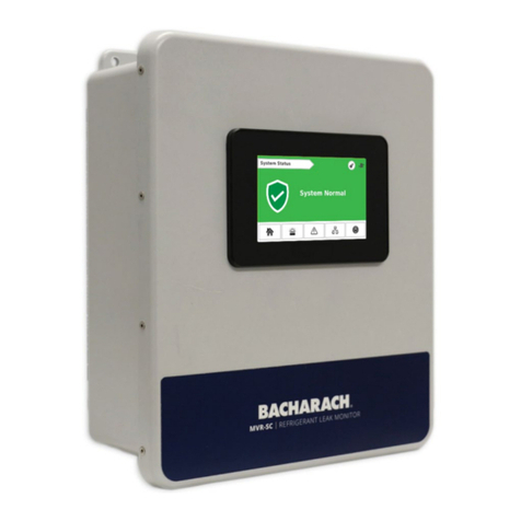
The MVR-SC Refrigerant Leak Monitor (MVR-SC) provides centralized
alarming andmonitoring for all connected MVR-300 Gas Detectors.
2.2.2 MVR-300 VRF Refrigerant Leak Detector
The MVR-300 VRF Refrigerant Leak Detector (MVR-300) provides
refrigerant leak detection for occupied rooms in VRF applications.
2.2.3 Ethernet Network Switch
An Ethernet network switch is used to provide connectivity between the
MVR-SC Controller and the individual Modbus Gateways (up to 8 ports).
2.2.4 Gateway
A gateway is used to create small networks of MVR-300 Refrigerant
Detectors (up to 15 per gateway) to ease installation andtroubleshooting.
2.2.5 Modbus EZ-Wire Kit
Precisely stripped, pre-bonded wire provides faster, more consistent
installation to the MVR-300 Modbus port.

1100-2294 Rev 1 12
2.3 HardwareOverview
MVR-SC Refrigerant Leak Monitor
The MVR-SC provides centralized alarming and monitoring for all connected MVR-300 Gas
Detectors.
Figure 6 - MVR-SC Overview
#
Component Description
1
PLC / Touch Screen
2
Fault Relay
3
Alarm Relay
4
Modbus
5
Power (24V DC IN)
6
Cable Entries (×4)

1100-2294 Rev 1 13
3 Installation
3.1 NetworkOverview
IMPORTANT: Prior to installation, download the MVR-SC floorplan spreadsheet
available from MyBacharach.com or on the USB stick supplied with the
controller. This spreadsheet has editable fields for Floor / Room and non-editable
fields for Modbus ID and Gateway IP address. The floor and room fields are to be
completed prior to installation in order to ensure correct wiring and function.
Up to 100 MVR-300 devices can be connected to the MVR-SC. These are to be grouped as
Modbus RTU daisy-chain segments of up to 15 devices, terminating at a Gateway. Up to
seven gateways can be used in a fully populated network.
Gateways connect via an Ethernet TCP network, through an Ethernet switch, to the MVR-SC.
Up to seven gateways can be used in a fully populated network. The MVR-SC provides
centralized monitoring of all devices in the network, with a 15-second scan rate.
When creating the floorplan, follow these conditions:
Keep daisy-chain segments of MVR-300 devices as near as possible to the
gateway to which they connect.
We recommend keeping this distance under 500 ft., if possible, for Modbus
daisy-chain segments. As wire length increases, noise sources can accumulate,
and a greater degree of attention to shielding and grounding is required.
It is important that the designations in the floorplan spreadsheet “data.csv”
exactly match the actual installed network. Any changes in the physical wiring
must be reflected in the spreadsheet for the system to function.
The following diagram shows an example network using all seven Gateways.
Figure 7 - Connection Diagram

1100-2294 Rev 1 14
Network Creating Notes:
To mark devices to be on the same floor, those devices must have the same
floor name (capitalization matters). The MVR-SC will display a new “floor” tile for
each unique name appearing in the floorplan spreadsheet, up to 16 district
values.
The floor and room cells can be named with any combination of up to eight digits
of letters and/or numbers.
It is possible to hardwire up to 15 devices to the controller’s Modbus RTU port.
To indicate these in the floorplan, fill in the cells at the bottom of the spreadsheet
(rows with IP marked “Direct”).
Each Gateway’s IP Address must be unique. If only one gateway is used, its IP
address should be 192.168.0.1. The IP address for subsequent gateways would
be 192.168.0.2, 192.168.0.3, etc.
The 7th gateway, if used, has a limit of 10 devices. All other gateways have a
limit of 15 devices.
Figure 8 –Small Example Network

1100-2294 Rev 1 15
3.2 FloorplanSpreadsheet(CSV)
The MVR-SC floorplan spreadsheet (data.csv) is intended to be edited on a PC, and then
uploaded to the controller via the USB stick. The spreadsheet contains placeholder entries for
all possible devices in the network, but only those with “floor” and “room” cells populated will
be active and displayed.
Insert the USB stick into a computer that has Excel software installed.
1. Open the flash drive and click the example CSV file titled “data.csv.”
In this file, there are columns labeled: Index, Floor, Room, Gateway, Modbus ID, and
IPAddress.Of those six columns ONLY the middle three (Floor, Room, and Gateway)
can be edited.
.
Figure 10 - Click the .CSV File
Figure 9 - The MVR-SC Floorplan Spreadsheet

1100-2294 Rev 1 16
2. Add your floors and rooms to match the floorplan that has been designed for this specific
building layout.
3. Save the floorplan spreadsheet as a .csv format and upload it onto the USB stick at the
device root folder. The filename must be named as “data.csv.” or the MVR-SC will not be
able to find the file when importing.
4. Upload the spreadsheet into the controller from the USB stick using the steps outlined in
Section Error! Reference source not found., Error! Reference source not found..
Special Notes:
There can be multiple gateways on a given floor and is not limited to one
gateway per floor.
To have floors in numeric order, have them listed as such in the “data.csv” file.
The “data.csv” file does not do any interior or alphabetical sorting.
Every assigned room in the “data.csv” file must have a Modbus number
assigned.
The column titled “Gateway” is optional and nothing in that column will appear on
the MVR-SC.
Do not add text into any text boxes to the right of Column F and/or below row
114, or the MVR-SC will not be able to read the file.
Figure 11 - Example Layout

1100-2294 Rev 1 17
3.3 GatewayIPAddress
Each gateway in the system requires a unique IP address.
The MVR-SC connects to upto seven gateways, using the following default IP address
scheme.
,
The IP addressfor each Gatewaymay need to be changed by the user, since they ship with
default IP 192.168.0.1. This can be done using a windows PC andthe free Moxautility.
Steps to change Gateway IP addresses:
1. Connect the first Gateway to be changed to a PC using either Ethernet port. Power the
gateway with 24VDC.
2. Download MGate Manager for windowsfrom:
a. https://moxa.com/en/products/industrial-edge-connectivity/protocol-
gateways/modbus-tcp-gateways/mgate-mb3170-mb3270-series#resources
b. Direct Zip download link
3. Open the MGate Manager Application. Press the “Search” Button to start looking for
devices
Order
IP for Gateway
MVR-300 device count
1
192.168.0.1
15
2
192.168.0.2
15
3
192.168.0.3
15
4
192.168.0.4
15
5
192.168.0.5
15
6
192.168.0.6
15
7
192.168.0.7
10
Figure 12 –Mgate Manager for Windows

1100-2294 Rev 1 18
4. Choose Broadcast Search to search on the entire connected
5. When discovered, the Gatewayshould show up in the table. Select its row and press
Configuration.
a. Note: if this step requires a password it is “moxa”
6. Navigate to the Network tab (the second tab).
Figure 15 - Network tab
7. In the Network tab you will be able to set the IP. Change the IP from “192.168.0.1” to the
IP that corresponds with your Gateway index (1 –7) from the chart above.
Figure 13 –Broadcast Search
Figure 14 –Gateway Configuration

1100-2294 Rev 1 19
8. If this gateway is the first in the network, its IP address is already correct –192.168.0.1. If
it is the second, change the last digit to match –192.168.0.2, etc.
9. Repeat this process for the remaining gateways in the system.
The gateways contain powerfulbuilt-in troubleshooting features. If system
troubleshooting is required, please reach out to Bacharach Product Support for
relevant documentation and support.
Figure 16 - Network Setting OK screen

1100-2294 Rev 1 20
3.4 HardwareInstallation
Mountthe MVR-SC in an accessible location for viewing alertsand responding to alarm
conditions.
Environment: place the MVR-SC in an indoor setting free from the risk of
exposure to water, high humidity or any hazardousconditions.
Accessibility: ensure that the MVR-SC’s touch screen is readily accessible for
viewing alerts and responding to alarm conditions.
1. Connect thecontroller to a 24V DC, rated power supply.
Near to the 24V DC is a terminal block for direct Modbus RTUconnections.
This is to be used for troubleshooting or very small direct-connected networks less than 15
units. A typical largefloorplan should be divided into segments connecting via Gateways, as
described earlier.
WARNING: Do not apply power until all wiring is in place.
Figure 17 - Modbus Wiring
Other manuals for MVR-SC
2
Table of contents
Other Bacharach Controllers manuals

Bacharach
Bacharach MGS-408 User manual

Bacharach
Bacharach MGS SERIES User manual

Bacharach
Bacharach MVR-SC User manual

Bacharach
Bacharach MGS SERIES User manual

Bacharach
Bacharach MGS SERIES User manual

Bacharach
Bacharach MGS-402 User manual

Bacharach
Bacharach MVR-SC User manual

Bacharach
Bacharach MGS-408 User manual
Popular Controllers manuals by other brands

Nobile
Nobile NobiLED 5920/RGB user manual

Green Air Products
Green Air Products CDMC-6 Installation and operation manual

Lunos
Lunos 5/UNI-FR installation manual

Omron
Omron CPM1 - PROGRAMING 02-2001 Operation manual

National Instruments
National Instruments CompactRIO sbRIO-9603 Hardware installation manual

DX Engineering
DX Engineering DXE-NCC-2 quick start guide