Progeny P3 User manual

Page 1
P3 Lift Controllers
3007-2F (2 floors, two shafts)
3007-4F (4 floors, two shafts)

Page 2
IMPORTANT SAFETY NOTES
Please read this manual carefully before attempting to install, program or operate the Progeny access control
equipment.
This equipment must be installed in line with all relevant regulations and standards.
Make sure that wiring is rated according to fuses and current limits of relevant power supplies.
Apart from the mains supply all connections to this unit must be SELV level. (Safety Extra Low Voltage, BS EN 60950
1992)
No users should access inside the control box. The control box contains hazardous voltages and access is limited to
qualified personnel only. All user programming for the controller is either done at one of the keyboards or at the PC.
Every effort is made to ensure that this manual is complete and free from errors. However we reserve the right to
make changes to these products and this manual without notice.
No liability is accepted for loss damage or injury as a consequence of using these products or instructions.
Onsite training is available and telephone technical support (08:30 –17:00, Mon –Fri) with optional remote access for
further assistance is all part of the support we can offer.
For further details and assistance contact us on +44 (0) 844 811 8976 or email us on:
support@progeny.co.uk
www.progeny.co.uk
Document Numbers:
3007-2F
3007-4F
Date:
26-03-2012
Issue:
03
Firmware Version
3.35 and Later
EMC
Certificate Number A8281
Copyright BSB Electronics Ltd 2012 All rights reserved.

Page 3
Contents
IMPORTANT SAFETY NOTES.....................................................2
Introduction.................................................................................4
Additional Equipment Required..............................................................................4
What’s in the Box?...................................................................................................5
Installation...................................................................................6
Mounting ..................................................................................................................6
Power........................................................................................................................6
Reader Connections................................................................................................6
Connecting to the Lift Control Box.........................................................................7
Lock Relay Wiring Key (Clean Contact).................................................................7
Network Connections..............................................................................................8
Connecting the P3 lift controller to a P3 or P3.net controller...............................8
Reset Button ............................................................................................................8
Control Board LEDs.................................................................................................8
SPECIFICATIONS ........................................................................9
Controller Parameters.............................................................................................9
Card Channel ...........................................................................................................9
Controller Enclosure ...............................................................................................9
Relay Outputs ..........................................................................................................9
Network ....................................................................................................................9
Inputs........................................................................................................................9
Status .......................................................................................................................9
Safety Notes and Disclaimers...............................................................................10

Page 4
Introduction
The P3 Lift Controllers are available as either 2 floor, 2 shaft controllers (3007-2F) or 4 floor, 2 shaft controllers (3007-4F).
The lift controllers can be added to an existing P3 system allowing for lift access to be controlled with a single reader in
the lift cab. The reader in the lift cab is wired in parallel to each of the lift controllers. The relays are triggered on the
relevant controllers when a valid credential transaction takes place at the reader. These relays are used to interact with
the lift control panel which in turn allows the user to press the button for the floor that access was granted for.
Access must be set up using the access level functions of the P3 software, Doors Enterprise. It is therefore necessary to
network the controllers back to the PC running Doors Enterprise. This can be achieved by either creating a new
connection or by utilising a RS485 cable run of an existing P3 connector. Each lift controller circuit board has its own
unique controller ID number and is treat in exactly the same way as a standard P3 Door Controller. Simply add the
controller ID number in to Doors Enterprise when adding the controllers on to the system. The system treats the lift
controllers as doors. Once added simply add the controllers on to the relevant access levels as required.
Two shafts can be controlled from a single controller by setting the individual controllers to “turnstile” mode. This is a
feature of P3 which allows the two relays on the controller to operate independently of each other. Valid Reader A
transactions trigger the main lock relay whilst valid Reader B transactions trigger Relay B. Therefore, if the building has
two lifts in two shafts, the reader from the lift cab in shaft A can be wired back to the Reader A terminals whilst the reader
in the cab of shaft B can be wired back to the Reader B terminals of the lift controllers. Note that the main relay marked
as “lock” on the lift controller is a powered relay and that another relay may be required to switch this to clean contact for
integration with the lift control panel (check to see what the lift control panel requires).
Additional Equipment Required
12V DC PSU (the Progeny 2071 is suitable)
If using the controllers to operate two shafts then another relay will be required per lift controller circuit board to
switch the “lock” relay from powered to clean contact.
Suitable screened cable to allow the reader to connect to the lift controllers from the lift cab

Page 5
What’s in the Box?
When opening the box you should have the following:
3007-2F (2 floor, 2 shaft)
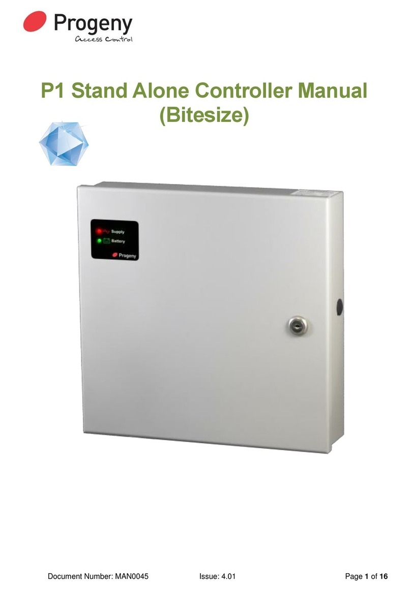
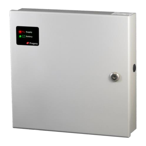
1 x 3007-2F (Steel enclosure with cam lock containing two pre-wired lift controllers)
2 x Cam lock keys
3007-4F (4 floor, 2 shaft)
1 x 3007-4F (Steel enclosure with cam lock containing four pre-wired lift controllers)
2 x Cam lock keys

Page 6
Installation
Mounting
The optimum location for the controller depends on the application. As a general guide:
Always mount the control equipment on the secure side of a door.
Mount as close as possible to the lift control panel to be controlled.
Keep the controllers away from any excessive heat source (the lift controller operating temperature range is between
-15C and 60C).
The reader cable should not exceed 100m in length between reader and lift controller (40m for bar code reader).
Offer the opened back of the enclosure up to the wall where the unit is to be mounted and mark the location of the fixing
dimples on the wall. Drill and plug the wall. Bring in mains supply and other cables that are to enter via the rear cable
access holes. Screw the controller to the wall.
WARNING: Extreme caution must be used when opening the controller housing. DO NOT touch any connections
or components other than the reset button. Avoid touching any of the terminations with a metal object such as a
wristwatch or jewellery.
Power
The lift controllers require a 24 hour 12V DC supply. The PSU should be fitted on a fused spur and the cable between
spur and PSU should be 0.75 to 2mm². The cable between PSU and controller should be 16 strand per core with 0.2mm
core thickness. Carefully observe the polarity when making the connections. Connect the PSU to the lift controllers by
wiring the 12V and 0V to the 12V and 0V terminals on the keyboard connection. This connection is pre-wired between
the individual lift controllers so the connection between PSU and controller needs only to be made to one board in the
enclosure. If there is more than one enclosure, continue the power connection from the last.
Product
Recommended Power Output of PSU
3007-2F
1A at 12V DC
3007-4F
2A at 12V DC
Reader Connections
The reader in the cab should be connected back to the lift controllers using a suitable screened cable for use with lifts.
The lift control circuit boards are pre-wired so that the reader connections are in parallel. To connect the reader in the
cab to the controller simply wire to the terminal block of the reader input. It is suggested that the circuit board mounted
top left is used to create the connection. If you are using more than one lift controller enclosure and are continuing a
connection from one to the next then the reader connection from enclosure to enclosure should be made from the circuit
board mounted bottom right, to the circuit board mounted top left of the next enclosure. Remember to earth the reader
screen.
Card Reader Connection Table
Lift Controller
2058
2075
2030
2052
3824
Proximity
Reader
Magnetic
Stripe Reader
Barcode
Reader
Pointprox
Reader
Crystal
Proximity
Reader
12V
+12V
Red
~
Red
+12V
5V
~
~
Red
~
~
DAT
D1
White
Violet
White
X
CLK
D0
Green
Green
Green
Y
0V
0V
Black
Black
Black
0V & D
Yellow
INT OUT LMP (optional)
LED
Orange
Brown
Orange
A
EARTH STUD
Earth
Earth
Matt Black
Drain
Screen

Page 7
When connecting the reader, it is only necessary to connect the positive connection to the first controller. The 0V from
the reader should be connected to each controller in turn.
Connecting to the Lift Control Box
The output relays which are being used on each lift control circuit board should be used to interact with the lift control box.
Due to there being a wide variance in lift control box design, the lift control documentation should be consulted to
determine what signal from the lift controller is required.
As a guide, the lift controller has two relay outputs on each circuit board. Please note the following key for the output
relay labelled “Lock”:
Lock Relay Wiring Key (Clean Contact)
12/24V = C
VA = NO
VR = NC
0V = Not used
The output labelled “Relay B” is a clean contact relay. By default the lift controller will trigger both relays on the circuit
board at the same time.
If the controller is controlling two shafts then the controller needs to be re-configured to run in “turnstile” mode. This is
done from within Doors Enterprise (please consult the software manual on how to configure the relays). Setting the
controller to turnstile mode sets each relay to work independently of each other, allowing Reader A to control the “Lock”
relay whilst Reader B controls “Relay B”.This then provides a relay for each shafts’ control box.
Wiring Guide

Page 8
Network Connections
The network used to link the controllers back to a central point is “RS 485”. This allows full duplex communication and
requires a special cable type (Belden 8132, 8131 or equivalent).
The 8132 has two twisted pairs the 8131 has one pair. Both have an overall screen and drain wire. When pulling the
cable into place, be careful to avoid Fluorescent lighting ballast's and large mains transformers, motors and switchgear.
When terminating strip back the cable sufficiently to identify the twisted pairs of cores.
Connecting the P3 lift controller to a P3 or P3.net controller.
All P3.net, P3 and P3 lift controllers labelled V3.xx (the firmware version number is located on the PIC chip on the
controller PCB. Note that boards that have the PIC soldered on to the PCB are version 3.35) have the network
connections identified with “A” and “B” simply connect A to A and B to B. When connecting a P3 lift controller to an earlier
V1.xx or 2.xx P3 controller then the connections are marked “RX” and “/RX”. In this case connect A to RX and B to /RX.
It is important to use the colour coding and keep the twisted pairs for connections as shown above. At each
controller the incoming and outgoing screens should be connected together. Connect the drain wires to the
chassis earth stud at the first controller only. It is also important that the network be one daisy chain with no
spurs or loops.
Reset Button
The reset button allows the engineer to perform a factory reset. This resets all parameters to the factory default values
and removes all user programmed credential data and configuration settings.
The reset button needs to be held for approximately 7 seconds or until the keyboard LED starts to flash to start the reset
sequence. The keyboard LED will display a flashing sequence to indicate the start of factory reset.
Control Board LEDs
READER "A" & "B" LED
Meaning
Off
Stand by
On
Door opened
Flashing sequence
Error
NETWORK LED’s
Meaning
POLL LED Flashing
Data specific to the controller received
DATA LED Flashing
Data on the network
OFF
No Network Activity
A
B
RX
RX
P3 Controller
(V1.xx or
V2.xx)
P3 Controller
(V3.xx)

Page 9
SPECIFICATIONS
Controller Parameters
Event Memory 2000 time date stamped
Time Zones 64
Time elements 255
Calendars 8
Card Channel
Cards with host site code Up to 10,000
Custom Card Formats 36 as standard + user defined
Reader Technologies Proximity, Wiegand, Barcode,
Magstripe, Biometric.
Two Reader Inputs “Reader A” –“Reader B”
Reader supplies 12V @ 500mA current limited
5V @ 100mA current limited
Cables 6 core screened 100m max cable run (40m for bar code readers)
Controller Enclosure
Dimensions: 310mm, 330mm, 90mm
Power Draw Allow a minimum of 500mA per lift controller circuit board
Relay Outputs
Lock Output Relay 3.0 Amps at 30V DC
Relay B contact ratings 3.0 Amps at 30V DC
Relay B Modes 12
Lock Timer 1 to 99 seconds
0 = Toggle mode
Network
RS 485 (2 wire) Half Duplex
Cables BELDEN 8133, or 8132 1000m max
Inputs
Reader
Status
Interlock LMP Output For optional LED control

Page 10
Safety Notes and Disclaimers
Please read this manual carefully before attempting to install, program or operate
the Progeny Chameleon access control equipment.
This equipment must be installed in line with all relevant regulations and standards.
This equipment should be powered by a power supply classed as SELV, as defined
in BS EN 60950. All connections to this unit must also be SELV.
Make sure that wiring is rated according to fuses and current limits of relevant
power supplies.
Every effort is made to ensure that this manual is complete and free from errors.
However we reserve the right to make changes to these products and this manual
without notice.
No liability is accepted for loss damage or injury as a consequence of using these
products or instructions.
Copyright BSB Electronics Ltd 2012 All rights reserved.
Doc Number 3007-nF Date 01/03/13 Issue 03
Keep important information here:
INSTALLATION DATE _______________________________
Notes:
Other manuals for P3
1
Table of contents
Other Progeny Controllers manuals
