manuals.online logo
Brands
  1. Home
  2. •
  3. Brands
  4. •
  5. Bacharach
  6. •
  7. Controllers
  8. •
  9. Bacharach MVR-SC User manual

Bacharach MVR-SC User manual

1
2
3
Ethernet
Switch
1
2
3
1
2
3
1
2
3
Refrigerant Leak Detection
P/N: 1100-2162 | June 2019 Revision 0
Quick Start
Guide
Refrigerant Leak Monitor
System Controller for MVR-300 Refrigerant Detectors 3. Component Overview
5. Network Planning
4. Accessories
Bacharach, Inc.
621 Hunt Valley Circle,
New Kensington, PA 15068 USA
Bacharach USA Customer Service: +1 724 334 5000
Bacharach CAN Customer Service: +1 905 882 8985
Bacharach EU Customer Service: +353 1 284 6388
mybacharach.com | [email protected]
IMPORTANT: The MVR-SC must be installed by a suitably qualied
technician who will install this unit in accordance with these
instructions and the standards in their particular industry / country.
This document is only intended as a guide and the manufacturer
bears no responsibility for the installation or operation of this unit.
2. Safety Instructions (Continued)
IMPORTANT: Comply with all local and national laws, rules and
regulations associated with this equipment. Operators should be
aware of the regulations and standards in their industry / locality
for the operation of the MVR-SC.
IMPORTANT: Prior to installation, download the MVR-SC oorplan
spreadsheet available from Bacharach. This sheet has editable
elds for Floor / Room and non-editable elds for Modbus ID
and Gateway IP address. These elds are to be completed during
planning in order to ensure correct wiring and function:
Floor / Room
Modbus (Slave) ID − number between 2 and 16. Refer to the MVR-
SC User Manual (P/N: 1100-2184) for more details on Modbus
connectivity.
Gateway IP Address − Each gateway has a unique, required IP
address. (The rst should be 192.168.0.1, followed by 192.168.0.2
and so forth. A maximum of 7 gateways may be connected in a
subnetwork.)
CSV Spreadsheet − le will need to be saved in a .CSV format in
order to upload to the MVR-SC.
1. Save the oorplan spreadsheet as a .CSV format and
upload onto the USB stick at the device root folder. The
lename must be “data.csv.”
2. Upload the oorplan spreadsheet to the MVR-SC from the
USB stick using steps on the next page.
Figure A (System Conguration)
DANGER: This product HAS NOT been designed for use in
hazardous locations. Failure to comply may result in personal
injury or death.
WARNING: NEVER connect the product’s 24V DC inputs directly
to AC power supply.
WARNING: DO NOT apply power until all wiring has been
completed.
CAUTION: The protection provided by this product may
become impaired if it is used in a manner not specied by the
manufacturer. Modications to this instrument, not expressly
approved, will void the warranty.
CAUTION: DO NOT continue to use this equipment if there are
any symptoms of malfunction or failure. In the case of such
occurrence, de-energize the power supply and contact a qualied
repair technician or the nearest Bacharach Service Center.
IMPORTANT: Before using this product, carefully read and
strictly FOLLOW THE INSTRUCTIONS in the user manual.
1. Introduction
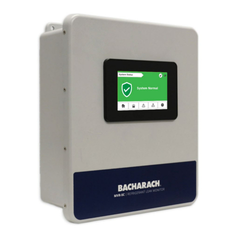
The MVR-SC Refrigerant Leak Monitor provides infomation and
audio-visual alerts on the status of a network of refrigerant
detectors in a centralized location outside of the monitored
space. The MVR-SC displays comprehensive information about
the status of all connected gas detectors and is compatible with
Bacharach’s MVR-300 VRF Refrigerant Leak Detector.
Additional resources (including the user manual &
oorplan spreadsheet) are available online. To download
these resources, scan here or visit http://bit.ly/2MdlvyP.
2. Safety Instructions
# COMPONENT DESCRIPTION
1PLC / Touch Screen
2USB Port
3Ethernet Port
(Requires Shielded Cat 6 Cable)
4Fault Relay
(250 VAC / 30 VDC, 2.0 AMP)
5Alarm Relay
(250 VAC / 30 VDC, 2.0 AMP)
6Modbus Terminal Block
(Requires Belden 3106 or Equivalent. Shielded 1.5 pair twisted)
7Power
(24 VDC IN)
8Cable Entries (×4)
Modbus Cable Description 1,000' (304.8 m) spool of industrial-grade Modbus cable.
P/N: 1100-2193
Ethernet Switch Description Connects the MVR-SC and individual gateways.
P/N: 1100-2172
Modbus Gateway Description Each gateway supports a network of up to 15 MVR-300 VRF
Refrigerant Leak Detectors.
P/N: 1100-2198
Modbus EZ-Wire Kit Description Precisely stripped, pre-bonded wire provides faster, more
consistent installation to the MVR-300 Modbus port.
P/N: 1100-2190
Product Description / Part Number
3
4
5
76
8
B.
C.
6. Installation
WARNING: NEVER connect the product’s 24V DC inputs directly
to AC power supply.
WARNING: DO NOT apply power until all wiring has been
completed.
2
1

PowerModbus
Alarm RelayFault Relay
Ethernet (on side)
Modbus
12345
Magnetic
Switch B
Magnetic
Switch A
Figure F. (Magnetic Switch Locations)
Additional resources for the MVR-300 VRF Refrigerant
Leak Detector are available online. To download these
resources, scan here or visit http://bit.ly/2wr9eMn.
7. Network Setup
STEP A | Upload the Floorplan into MemorySTEP A | Mounting the MVR-SC Refrigerant Leak Monitor STEP C | Connecting Gateways
STEP B | Connecting Relays (User Discretion)
STEP B | Commission MVR-300s (Continued)
4. After the Network Conguration Screen ( )appears, select
Upload CSV to load the oorplan spreadsheet into memory
and generate all oors / device groupings.
1. Conrm that the display turns on. After the First-time
Setup Screen appears, select the Settings icon ( ).
When prompted, enter the passcode (default is “6388”).
2. After the Settings Screen ( )appears, connect the USB
stick which contains the planning spreadsheet to the
controller.
3. Select Network Conguration.
Optionally, the MVR-300 may be taken out of this mode by
briey tapping Magnetic Switch B (··).
7. Select the Commission Button ( )next to the appropriate room.
8. Select Commission Device to push the correct Modbus ID
to the active MVR-300 and enable Modbus polling. (A green
checkmark will appear once the device has been paired.)
After activation, each room tile will display the following:
• Floor / Room Number
• Gateway IP Address
• Assigned Modbus ID
• Device Status (Normal, Alarm, Fault, Comm. Error)
6. Installation (Continued)
1. Mount the MVR-SC according to the product dimensions
and following considerations:
• Environment: place the MVR-SC in an indoor setting free
from the risk of exposure to water, high humidity or any
hazardous conditions.
• Accessibility: ensure that the MVR-SC’s touch screen is
readily accessible for viewing alerts and responding to
alarm conditions.
2. Connect the controller to a 24V DC, rated power supply.
Figure B. (Power & Modbus Connections)
3. If used, connect the relay output(s) to equipment that will
be triggered by the relay. (Take care to ensure proper wiring
for intended function: normally open and / or normally closed.)
Figure C. (Relay Connections)
4. Using Cat 6 cable, connect the Ethernet output from the
controller to the gateway(s).
If multiple gateways are in use, use an Ethernet switch to
connect all gateways and the MVR-SC onto the same local
subnetwork.
5. Connect the Modbus cable to the gateway output as
depicted below.
Figure D. (Modbus Connection to Ethernet Gateway)
Pins 1 and 2 are not used. The Modbus cable shield may be
left oating or tied to G (electrical ground) at the gateway only.
6. Each gateway can support a maximum of 15 MVR-300 leak
detectors connected in a daisy chain fashion using Modbus
network cable.
A+ (Modbus) Orange
B- (Modbus) White
G (Modbus) Blue
(Power) Green / Yellow
- (Power) White
+ (Power) Red
Common White
Normally Closed Blue
Normally Open Black
3A+ (Modbus) Orange
4 B- (Modbus) White
5 G (Modbus) Blue
7. Leaving no more than 12″ (30.5 cm) for the single wire tie-o
to each MVR-300, connect to the Modbus port as depicted
in the gure below.
For faster, more consistent installation, use the Modbus
EZ-wire kit (P/N: 1100-2190) to connect each MVR-300.
Figure E. (Modbus Connection to MVR-300)
STEP D | Connecting MVR-300 VRF Refrigerant Leak Detectors
9. Repeat these steps for each room on a oor and each oor
in the building until all MVR-300s have been commissioned.
The Home Screen will display “System Normal” once all
MVR-300s have been commissioned.
STEP B | Commission MVR-300s
5. Access the Floors Screen ( ) and select the desired oor.
Each room / device marked with the same oor name in
the planning spreadsheet will be grouped onto that oor
block.
6. Working in coordination with a colleague, place one
MVR-300 into “commissioning mode” by briey (less than
1 second) tapping Magnetic Switch A (·).
A+ (Modbus) Orange
B- (Modbus) White
G (Modbus) Blue

Other manuals for MVR-SC

2

Other Bacharach Controllers manuals

Bacharach MGS-408 User manual

Bacharach

Bacharach MGS-408 User manual

Bacharach MVR-SC User manual

Bacharach

Bacharach MVR-SC User manual

Bacharach MGS-408 User manual

Bacharach

Bacharach MGS-408 User manual

Bacharach MGS-402 User manual

Bacharach

Bacharach MGS-402 User manual

Bacharach MGS SERIES User manual

Bacharach

Bacharach MGS SERIES User manual

Bacharach MVR-SC User manual

Bacharach

Bacharach MVR-SC User manual

Bacharach MGS SERIES User manual

Bacharach

Bacharach MGS SERIES User manual

Bacharach MGS SERIES User manual

Bacharach

Bacharach MGS SERIES User manual

Popular Controllers manuals by other brands

Bachmann E-Z Command Setup and Programming Instructions

Bachmann

Bachmann E-Z Command Setup and Programming Instructions

Command access MLRK1-JAC12 instructions

Command access

Command access MLRK1-JAC12 instructions

Siemens ET 200pro operating instructions

Siemens

Siemens ET 200pro operating instructions

Pharos DESIGNER LPC X installation instructions

Pharos

Pharos DESIGNER LPC X installation instructions

Griven AL1419 instruction manual

Griven

Griven AL1419 instruction manual

NEC N8190-158 user guide

NEC

NEC N8190-158 user guide

Hastings VT manual

Hastings

Hastings VT manual

Olimpia splendid Bi2 B0828 Instructions for mounting and use

Olimpia splendid

Olimpia splendid Bi2 B0828 Instructions for mounting and use

Advantech UNO-127 user manual

Advantech

Advantech UNO-127 user manual

FlowCon FN.0.2 Installation and operation instruction

FlowCon

FlowCon FN.0.2 Installation and operation instruction

Evoqua WALLACE & TIERNAN MFC instruction manual

Evoqua

Evoqua WALLACE & TIERNAN MFC instruction manual

Wilo SK 602N Installation and operating instructions

Wilo

Wilo SK 602N Installation and operating instructions

BEIER-Electronic SFR-1 operating manual

BEIER-Electronic

BEIER-Electronic SFR-1 operating manual

cherry creek systems NIC CHEAT SHEET

cherry creek systems

cherry creek systems NIC CHEAT SHEET

KE2 AdaptiveControl quick start guide

KE2

KE2 AdaptiveControl quick start guide

Mitsubishi Q64TCRT user manual

Mitsubishi

Mitsubishi Q64TCRT user manual

Baldor DBSC105-AAA-1 Installation and operating manual

Baldor

Baldor DBSC105-AAA-1 Installation and operating manual

Fisher FIELDVUE DVC6200 quick start guide

Fisher

Fisher FIELDVUE DVC6200 quick start guide

manuals.online logo
manuals.online logoBrands
  • About & Mission
  • Contact us
  • Privacy Policy
  • Terms and Conditions

Copyright 2025 Manuals.Online. All Rights Reserved.