Bacharach MGS 550 User manual

1: OPERATING AREA AND CONDITIONS
The Bacharach MGS-550 is an instrument for the
connuous monitoring of toxic and combusble gases,
oxygen and refrigerants in ambient air. The instrument
is housed in a rugged ABS or aluminum enclosure for
indoor and outdoor applicaons. The instrument can
be connected to a Bacharach monitoring system or a
Programmable Logic Controller (PLC). With the inte-
grated alarm relay configuraon, the instrument can
be operated as a stand-alone unit (with addional
local alarm signaling). The instrument is designed to
be installed in non-classified, non-hazardous, perma-
nent locaons.
The instrument is powered by 19.5 to 28.5 VDC or
24 VAC (± 20%). The measured gas concentraon is
converted to a 4 to 20 mA, 0 to 5 V, 0 to 10 V, 1 to 5 V,
2 to 10 V analog and digital Modbus RTU output
signal. The instrument accepts wire sizes of 16 to
24 AWG (0.2 to 1.5 mm2).
P/N: 1100-0999
Revision 0
June 5, 2015
2: SAFETY INSTRUCTIONS
USER MANUAL: Before using this equipment, carefully read
and strictly follow the User Manual (part number 1100-
1000). The user must fully understand and strictly observe
the instrucons. Use the equipment only for the purposes
listed and under the condions specified in that document.
CODE COMPLIANCE: Comply with all local and naonal
laws, rules and regulaons associated with this equipment.
GENUINE PARTS: Use only genuine Bacharach spare parts
and accessories, otherwise proper funconing of the equip-
ment may be impaired.
FLAME PROOF AND EXPLOSION PROOF JOINTS: Joints of
the flame proof/explosion proof enclosure are not in accor-
dance with the relevant minimum or maximum values of
EN/IEC 60079-1. The joints are not intended to be re-worked
by the user.
EXPLOSIVE DIRECTIVES: As long as no EC-Type Examinaon
Cerficate per Annex II, clauses 1.5.5, 1.5.6 and 1.5.7 of
Direcve 94/9/EC exists: the measuring funcon of the gas
detecon transmier for explosion protecon, according to
Annex II, clauses 1.5.5, 1.5.6 and 1.5.7 of Direcve 94/9/EC
is not covered.
When using the product in areas subject to explosion
hazards, refer to the following:
● Instruments or components for use in explosion-
hazard areas which have been tested and
approved according to naonal, European or
internaonal Explosion Protecon Regulaons
may only be used under the condions specified
in the approval and with consideraon of the
relevant legal regulaons.
● The instruments or components may not be
modified in any manner. The use of faulty or
incomplete parts is forbidden. The appropriate
regulaons must be observed at all mes when
carrying out repairs on these instruments or
components.
WARNING: Strictly follow the
instrucons in the User Manual
(part number 1100-1000).
CAUTION: DO NOT USE the MGS-550
in oxygen-enriched environments of
>21% oxygen. High “off-scale” read-
ings may indicate an explosive con-
centraon.
3: MOUNTING
ENVIRONMENTAL CONSIDERATIONS: Carefully consider the
full range of environmental condions to which the instru-
ments will be exposed.
TARGET GAS CONSIDERATIONS: The physical data of the gas
or vapor to be detected must be observed.
APPLICATION CONSIDERATIONS: The specifics of the appli-
caon (for example, possible leaks, air movement/dra, etc.)
must be observed.
ACCESSIBILITY CONSIDERATIONS: The degree of accessibil-
ity required for maintenance purposes must be granted.
ACCESSORY CONSIDERATIONS: The types of oponal and
accessory equipment that will be used with the system must
be kept in mind.
SENSOR POSITIONING: When installing the instrument or
the remote sensor, the sensor opening should always be
poinng downward.
SUN SHIELD CONSIDERATIONS: If the instrument is exposed
to direct sunlight, the use of a sunshield is recommended.
4: WEIGHTS AND DIMENSIONS (APPROXIMATE)
FULL-SIZE
MOUNTING
TEMPLATES --
DO NOT
RESCALE
115.0 mm (4.53 in)
120.6 mm (4.75 in)
Mounng
Point (ABS)
Mounng
Point (ABS)
Mounng
Point
(Ex d)
Mounng
Point (Ex d)
144.1 mm (5.67 in)
IP66-Rated ABS Enclosure
with Local
Sensor
Flame
Proof/
Explosion
Proof Ex d
Enclosure
with Local
Sensor
Magnec
Wand
COMPONENT WIDTH HEIGHT DEPTH
mm in mm in mm in
General Purpose Enclosure
Explosion Proof Encosure
210
125
8.3
4.9
225
190
8.9
7.5
85
90
3.4
3.5
kg lbs
1
1.6
2
3.5
WEIGHT

World Headquarters
621 Hunt Valley Circle
New Kensington, PA 15068 USA
Phone: 724-334-5000 • Fax: 724-334-5001
Toll Free: 1-800-736-4666
Website: www.MyBacharach.com
E-mail: help@MyBacharach.com
5: WIRING
1: Strip 0.2 to 0.25 inches (5 to 7 mm) of wiring
insulaon.
2: Connect the wires as indicated.
RELAY 1 NC
RELAY 1 C
RELAY 1 NO
RELAY 2 NC
RELAY 2 C
RELAY 2 NO
RELAY 3 NC
RELAY 3 C
RELAY 3 NO
10
11
12
13
14
15
16
17
18
Relay 1 Output
Relay 2 Output
Relay 3 Output
FUNCTION PIN LABEL
SHIELD WIRE WARNING: Con-
nect the shield of the power
wires to the earth ground of the
central control system (e.g.,
chassis, ground bus bar, etc.). NOTE: For connecons to an external controller
such as a Bacharach MGS or GDA, refer to the
manual that was included with the controller.
NOTE: For 24 VDC installaons,
the input is protected. If the
polarity is reversed, the instru-
ment will not power-up.
POLARITY WARNING: For 24 VAC installaons
in a daisy-chain configuraon, the neutral polar-
ity must be maintained for all instruments.
WARNING: The MGS-550 must be
powered by either (a) a suitable UL
60950/CSA cerfied power supply
that is isolated from line voltage by
double insulaon, or (b) an appro-
priately rated UL listed/CSA Class 2
transformer. Failure to comply can
result in personal injury or death.
M20 OPENINGS: The ABS and the
flame proof/explosion proof enclosures
provide four M20 openings for cable
glands or plugs. These openings can be
used for field wiring, direct aachment
of a sensor or wiring of a remote sensor.
Unused openings must be closed with a
suitable plug and gasket, maintaining
the IP or Ex d rang.
114A Georges Street Lower
Dun Laoghaire • Co Dublin • Ireland
Phone: +353 1 284 6388 • Fax: +353 1 284 6389
PIN 10
PIN 18
PIN 9
PIN 1
Connector Style
May Vary Slightly
from Photo
NOTE: To make wiring connecons,
you must first open the MGS-550
housing. The enclosure lid of the
IP66 ABS housing has four capve
screws. The enclosure lid of the Ex d
(flame proof/explosion proof) hous-
ing unscrews.
Next, carefully discon-
nect the combinaon
Display Bezel and
Processor Board (which
remain connected)
from the lower Inter-
face Board by unscrew-
ing the 3 capve
screws. Access the
capve screws through
holes in the Display
Bezel.
Internal
Display Bezel
(Top Layer)
Processor
Board
(Middle Layer)
with Keyed
Ribbon Cable
Interface Board
(Boom Layer)
NOTE: Aer wiring is completed, carefully
re-assemble the enclosure and its components,
nong the keyed ribbon cable and sensor connec-
tors. Aer installaon is complete, be sure to
refer to the User Manual (part number 1100-1000)
for detailed instrucons on registering the sensors
and configuring the MGS-550 for proper operaon.
PWR
GND
24VAC
PWR GND
24VAC
AC
POWER
PWR
GND
24VAC
PWR
GND
24VAC
PWR
GND
24VAC
PWR
GND
24VAC
PWR GND
24VAC
SUPPLY
TRANSFORMER
4-Wire Power and Output to
Central Control System
3-Wire Power and Output to
Central Control System
mA
A OUT 1
A1 GND
PWR GND
+24VDC
-
+
mA
A OUT 1
PWR GND
+24VDC
-
+
Refer to the User Manual (part number 1100-1000)
for detailed instrucons on accessing the internal
components for wiring.
+24VDC/AC
PWR GND
ANALOG 1 GND
ANALOG OUT 1
ANALOG 2 GND
ANALOG OUT 2
RS-485 GND
A
B
1
2
3
4
5
6
7
8
9
Power
(+24VDC or 24VAC)
Analog Output 1
Analog Output 2
Modbus RTU
FUNCTION PIN LABEL

1: RANGO Y CONDICIONES OPERATIVAS
El Bacharach MGS-550 es un instrumento diseñado para la
supervisión ininterrumpida de gases tóxicos y combusbles,
oxígeno y refrigerantes en el ambiente. El instrumento
viene alojado en un ABS o en una caja de aluminio
altamente resistentes para su instalación en interior y
exterior. El instrumento puede ir conectado a un sistema de
control Bacharach o a un controlador lógico programable
(PLC, siglas del inglés Programmable Logic Controller).
Gracias a su configuración de relé de alarma integrado, el
instrumento se puede operar como unidad autónoma (con
señalización de alarma local adicional). El instrumento ha
sido diseñado para su instalación permanente en lugares no
peligrosos y sin clasificar.
La alimentación del instrumento es de 19,5 a 28,5 V CC o
24 V CA (± 20 %). La concentración de gas medido se
convierte en una señal de salida de URT de Modbus
analógica y digital de 4 a 20 mA, 0 a 5 V, 0 a 10 V, 1 a 5 V y
2 a 10 V. El instrumento admite cables con dimensiones de
16 a 24 AWG (0,2 a 1,5 mm2).
N/P: 1100-0999
Revisión 0
5 de junio de 2015
2: INSTRUCCIONES DE SEGURIDAD
MANUAL DE USUARIO: Antes de ulizar este equipo, lea
con atención y siga al pie de la letra el Manual de usuario
(referencia 1100-1000). El usuario deberá comprender
íntegramente y respetar obligatoriamente las instrucciones.
Ulice el equipo solo para los fines indicados y en las
condiciones que se especifican en el documento.
CUMPLIMIENTO DE LA NORMATIVA: Deberá respetar la
legislación, normava y reglamentación locales y
nacionales asociadas al presente equipo.
PIEZAS ORIGINALES: Ulice únicamente repuestos y
accesorios originales Bacharach, de lo contrario podría
verse afectado el funcionamiento correcto del equipo.
JUNTAS ANTIDEFLAGRANTES Y A PRUEBA DE
EXPLOSIONES: Las juntas de la caja andeflagrante/a
prueba de explosiones no respetan los valores mínimo o
máximo de EN/CEI 60079-1. Las juntas no deberán ser
modificadas por el usuario.
DIRECTIVA SOBRE EXPLOSIVOS: Mientras no exista un
Cerficado de examen de po CE según el Anexo II,
cláusulas 1.5.5, 1.5.6 y 1.5.7 de la Direcva 94/9/CE: no se
cubrirá la función de medición del transmisor de detección
de gas para la protección contra explosiones según el Anexo
II, cláusulas 1.5.5, 1.5.6 y 1.5.7 de la Direcva 94/9/CE.
Cuando se vaya a ulizar el producto en zonas somedas a
peligros de explosión, consulte los siguientes puntos:
● Solo se podrán ulizar en zonas con peligro de
explosión los instrumentos y componentes que hayan
sido probados y aprobados de conformidad con el
reglamento para la protección contra explosiones
nacional, europeo o internacional, en las condiciones
especificadas en la aprobación y considerando el
reglamento legal relevante.
● Los instrumentos o componentes no se pueden
modificar bajo ningún concepto. Está prohibido el uso
de piezas defectuosas o incompletas. Se deberá
respetar la normava correspondiente en todo
momento a la hora de llevar a cabo las reparaciones de
dichos instrumentos o componentes.
ADVERTENCIA: Siga rigurosamente las
instrucciones del Manual de usuario
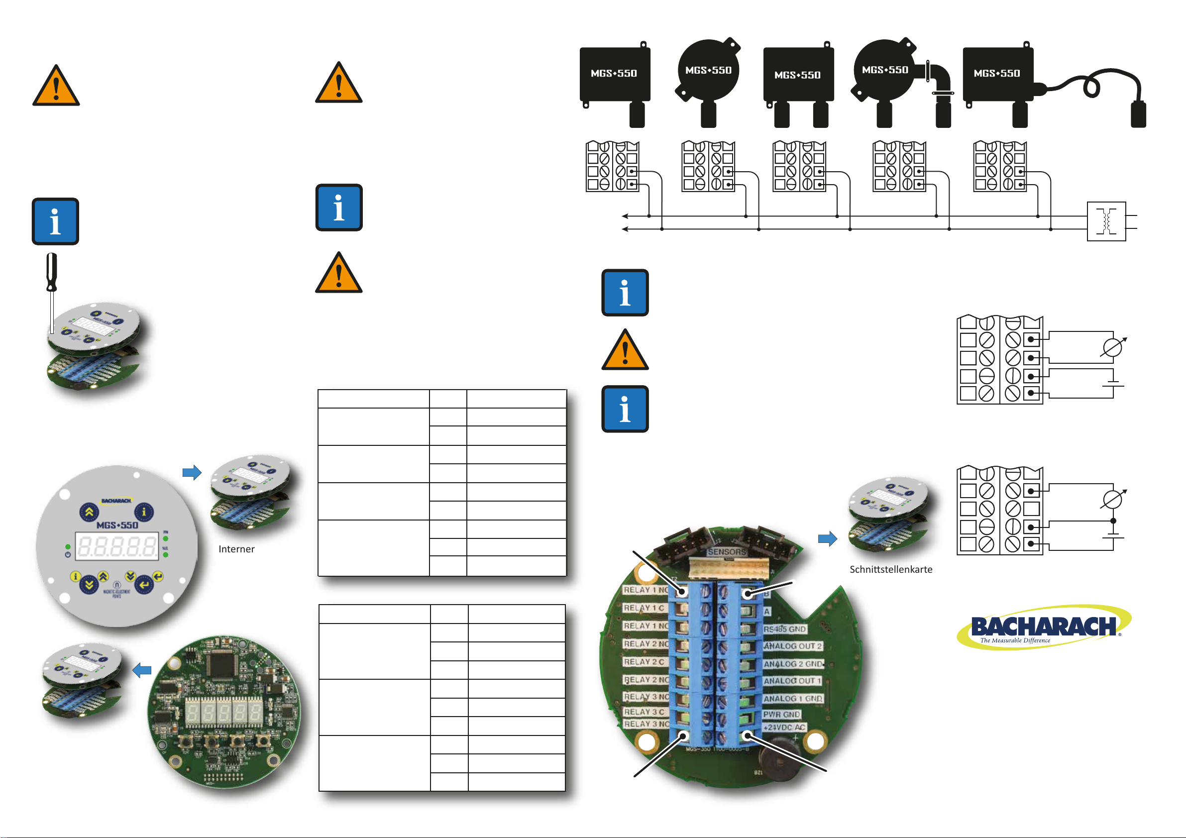
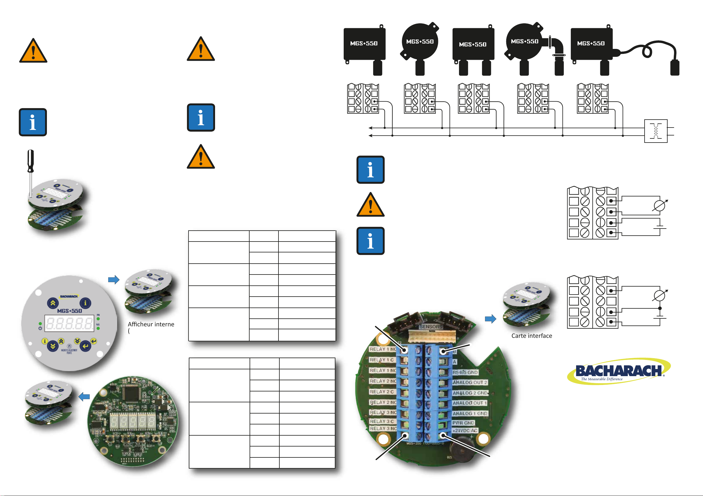
(referencia 1100-1000). 3: MONTAJE
PRECAUCIÓN: NO UTILICE el MGS-550 en
entornos enriquecidos con oxígeno con
más de un 21 % de oxígeno. Las lecturas
"fuera de escala" pueden ser indicavas
de una concentración explosiva.
CONSIDERACIONES MEDIOAMBIENTALES: Considere atentamente
el conjunto de condiciones medioambientales a las que se verán
expuestos los instrumentos.
CONSIDERACIONES SOBRE OBJETIVOS DE GAS: Se deben respetar
los datos sicos del gas o vapor que se va a detectar.
CONSIDERACIONES DE APLICACIÓN: Se deben observar los
puntos específicos de aplicación (por ejemplo, posibles fugas,
movimiento de aire/corriente, etc.).
CONSIDERACIONES DE ACCESIBILIDAD: Se debe garanzar el
grado de accesibilidad requerido para operaciones de
mantenimiento.
CONSIDERACIONES ADICIONALES: Se debe tener en cuenta el po
de equipamiento opcional y accesorio que se va a ulizar con el
sistema.
POSICIONAMIENTO DEL SENSOR: Al instalar el instrumento o el
sensor remoto, el orificio de apertura del sensor siempre deberá
apuntar hacia abajo.
CONSIDERACIONES DE PROTECCIÓN SOLAR: Si el instrumento
está expuesto a la radiación directa del sol, se recomienda ulizar
una pantalla solar.
4: PESOS Y DIMENSIONES (APROXIMADOS)
PLANTILLAS DE
INSTALACIÓN
A ESCALA
REAL -- NO
REDIMENSIONAR
115,0 mm (4,53 in)
120,6 mm (4,75 in)
Punto de
instalación
(ABS)
Punto de
instalación
(ABS)
Punto de
instalación
(Ex d)
Punto de
instalación
(Ex d)
144,1 mm (5,67 in)
Caja ABS de clase IP66
con sensor
local
Caja
Ex d
andeflagrante/
a prueba
de explosiones
con sensor
local
Vástago
magnéco
COMPONENTE ANCHO ALTO FONDO
mm in mm in mm in
Caja de uso general
Caja a prueba de explosiones
210
125
8,3
4,9
225
190
8,9
7,5
85
90
3,4
3,5
kg lb
1
1,6
2
3,5
PESO
TRANSMISOR DE GAS
Guía de instalación

Sede mundial
621 Hunt Valley Circle
New Kensington, PA 15068 EE. UU.
Teléfono: 724-334-5000 • Fax: 724-334-5001
Tel. gratuito: 1-800-736-4666
Web: www.MyBacharach.com
Correo electrónico: help@MyBacharach.com
5: CABLEADO
1: Pelar de 0,2 a 0,25 pulgadas (de 5 a 7 mm)
el aislamiento del cable.
2: Conectar los cables tal y como se indica.
RELAY 1 NC
RELAY 1 C
RELAY 1 NO
RELAY 2 NC
RELAY 2 C
RELAY 2 NO
RELAY 3 NC
RELAY 3 C
RELAY 3 NO
10
11
12
13
14
15
16
17
18
Salida relé 1
Salida relé 2
Salida relé 3
FUNCIÓN
CLAVIJA
ETIQUETA
ADVERTENCIA DE CABLE
BLINDADO: Conecte el blindaje de
los cables de alimentación a la toma
a erra del sistema de control
central (p. ej., chasis, barra de
contacto de erra, etc.).
NOTA: Para realizar conexiones a un controlador
externo como un Bacharach MGS o GDA, consulte el
manual que se adjunta al controlador.
NOTA: En instalaciones de 24 V CC la
entrada está protegida. Si se invierte
la polaridad, el instrumento no recibe
corriente.
ADVERTENCIA DE POLARIDAD: En instalaciones de
24 V CA con una configuración de cadena po
margarita, se debe mantener la polaridad neutra en
todos los instrumentos.
ADVERTENCIA: El MGS-550 debe
recibir alimentación de (a) una
fuente de alimentación UL 60950
adecuada/homologada por la CSA que
se aísle del voltaje de línea mediante
aislamiento doble, o de (b) un
transformador Clase 2 de régimen
adecuado cerficado por la UL/CSA. No
respetar esta información podría derivar
en lesiones personales o en la muerte.
ORIFICIOS M20: El ABS y las cajas
andeflagrantes/a prueba de explosiones
ofrecen cuatro orificios M20 para
empaquetaduras o clavijas de cable. Estos
orificios se pueden ulizar para el cableado
de campo, la instalación directa de un sensor
o el cableado de un servidor remoto. Los
orificios que no se hayan ulizado deberán
cerrarse con clavijas o empaquetaduras de
cable, manteniendo la clasificación IP o Ex d.
114A Georges Street Lower
Dun Laoghaire • Co Dublin • Irlanda
Teléfono: +353 1 284 6388 • Fax: +353 1 284 6389
CLAVIJA 10
CLAVIJA 18
CLAVIJA 9
CLAVIJA 1
Eslo de conector
Puede variar ligeramente
con respecto a la foto
NOTA: Para realizar las conexiones de
cableado, primero se debe abrir el
alojamiento MGS-550. La tapa de cierre
del alojamiento IP66 ABS ene cuatro
tornillos cauvos. Se desenrosca la tapa
de cierre del alojamiento Ex d
(andeflagrante/a prueba de explosiones).
A connuación,
desconecte con cuidado
el conjunto de la luneta
del visor y la placa del
procesador (que queda
conectado) de la placa
de interfaz inferior
desenroscando los
3 tornillos cauvos.
Acceda a los tornillos
cauvos a través de
los orificios de la luneta
del visor.
Luneta de
visor interno
(capa superior)
Placa del
procesador
(capa central)
con cable plano
con llave
Placa de interfaz
(capa inferior)
NOTA: Una vez finalizado el cableado, vuelva a instalar
la caja y sus componentes con mucho cuidado,
teniendo en cuenta el cable plano con llave
y los conectores de sensores. Una vez finalizada la
instalación, asegúrese de consultar en el Manual de
usuario (referencia 1100-1000) las instrucciones
detalladas sobre el registro de los sensores y la
configuración del MGS-550 para ver si funcionan
correctamente.
ALI.
TIE
24 V CA
ALI. TIE.
24 V CA
ALIMENTACIÓN
CA
ALI.
TIE.
24 V CA
ALI.
TIE.
24 V CA
ALI.
TIE
24 V CA
ALI.
TIE
24 V CA
ALI. TIE.
24 V CA
TRANSFORMADOR
DE ALIMENTACIÓN
Alimentación con 4 cables y salida
al sistema de control central
Alimentación con 3 cables y salida
al sistema de control central
mA
SAL. A 1
A1 TIE.
ALI. TIE.
+24 V CC
-
+
mA
SAL. A 1
ALI. TIE.
+24 V CC
-
+
Consulte en el Manual de usuario (referencia
1100-1000) las instrucciones detalladas para acceder
a los componentes internos para realizar su cableado.
+24VDC/AC
PWR GND
ANALOG 1 GND
ANALOG OUT 1
ANALOG 2 GND
ANALOG OUT 2
RS-485 GND
A
B
1
2
3
4
5
6
7
8
9
Alimentación eléctrica
(+24 V CC o 24 V CA)
Salida analógica 1
Salida analógica 2
URT Modbus
FUNCIÓN
CLAVIJA
ETIQUETA

1: OMGEVING EN OMSTANDIGHEDEN
GEBRUIK
De MGS-550 van Bacharach is een apparaat voor connue
controle op giige en brandbare gassen, zuurstof en
koelmiddelen in de omgevingslucht. Het apparaat zit in een
stevige behuizing van ABS of aluminium voor gebruik binnen
en buiten. Het apparaat kan worden aangesloten op een
controlesysteem van Bacharach of op een programmable
logic controller (PLC). Dankzij de geïntegreerde configurae
van het alarmrelais kan het apparaat worden gebruikt als
zelfstandige unit (met extra lokale alarmering). Het apparaat
is bestemd voor installae op niet-geclassificeerde,
niet-gevaarlijke, permanente locaes.
Voeding van het apparaat: 19,5–28,5 VDC of 24 VAC
(± 20%). De gemeten gasconcentrae wordt omgezet naar
een 4–20 mA, 0–5 V, 0–10 V, 1–5 V, 2–10 V analoog en
digitaal Modbus RTU outputsignaal. Het apparaat is
geschikt voor koperdoorsneden van 16–24 AWG
(0,2–1,5 mm2).
Arkelnr: 1100-0999
Versie 0
5 juni 2015
2: VEILIGHEIDSINSTRUCTIES
GEBRUIKERSHANDLEIDING: Lees voor gebruik van deze
apparatuur zorgvuldig de gebruikershandleiding
(onderdeelnummer 1100-1000) en volg de daarin
opgenomen instruces. De gebruiker dient volledig op de
hoogte te zijn van de instruces en deze strikt na te leven.
Gebruik de apparatuur alleen voor de vermelde doeleinden
en onder de in dit document beschreven omstandigheden.
NALEVING CODE: Neem alle lokale en naonale ween, regels
en voorschrien in acht die gelden voor deze apparatuur.
ORIGINELE ONDERDELEN: Gebruik uitsluitend de originele
onderdelen en hulpstukken van Bacharach, anders zal de
apparatuur misschien niet goed werken.
VLAMBESTENDIGE EN EXPLOSIEVEILIGE NADEN: De naden
van de vlambestendige/explosieveilige behuizing voldoen
niet aan de betreffende minimale of maximale waarden
volgens EN/IEC 60079-1. De naden zijn niet bestemd om te
worden bewerkt door de gebruiker.
RICHTLIJNEN MET BETREKKING TOT EXPLOSIEGEVAAR:
Indien er geen verklaring van het EG-typeonderzoek
conform bijlage II, bepaling 1.5.5, 1.5.6 en 1.5.7 van Richtlijn
94/9/EG beschikbaar is: dan valt de meeunce van de
gasdetece-zender, die is gericht op explosieveiligheid, in
overeenstemming met bijlage II, bepaling en 1.5.5, 1.5.6 en
1.5.7 van Richtlijn 94/9/EG, hier niet onder.
Zie voor gebruik van het product in een omgeving met
explosiegevaar de volgende informae:
● Apparaten en componenten die bestemd zijn voor gebruik
in een explosiegevaarlijke omgeving en die zijn getest en
goedgekeurd volgens de naonale, Europese of
internaonale voorschrien met betrekking tot
explosiebescherming, mogen uitsluitend worden gebruikt
onder de in de goedkeuring beschreven voorwaarden en
met inachtneming van de relevante weelijke bepalingen.
● De apparaten en componenten mogen op geen enkele
wijze worden aangepast. Het gebruik van defecte en
onvolledige onderdelen is verboden. De geldende
voorschrien voor het uitvoeren van reparaes aan
deze apparaten en componenten moeten te allen jde
worden nageleefd.
WAARSCHUWING: Volg nauwgezet de
instruces in de gebruikershandleiding
(onderdeelnummer 1100-1000).
LET OP: GEBRUIK de MGS-550 NIET in
zuurstofrijke omgevingen met > 21%
zuurstof. Hoge waarden buiten het
meetbereik kunnen duiden op een
explosieve concentrae.
3: MONTAGE
AANDACHTSPUNTEN OMGEVING: Houd rekening met alle
omgevingsomstandigheden waaraan de apparaten zullen
worden blootgesteld.
AANDACHTSPUNTEN TE DETECTEREN GAS: Het uitgangspunt
wordt gevormd door de fysieke kenmerken van het te detecteren
gas of de te detecteren damp.
AANDACHTSPUNTEN TOEPASSING: U dient te voldoen aan de
specifieke eisen die gelden voor de toepassing (bijvoorbeeld
mogelijke lekken, luchtverplaatsing/tocht enz.).
AANDACHTSPUNTEN TOEGANKELIJKHEID: Zorg dat de
toegankelijkheid die nodig is voor onderhoud gewaarborgd is.
AANDACHTSPUNTEN HULPSTUKKEN: Let op de typen van
oponele en aanvullende hulpstukken die voor de apparatuur
worden gebruikt in combinae met het systeem.
POSITIONERING VAN DE SENSOR: Bij het installeren van het
apparaat en de externe sensor moet de sensoropening aljd
omlaag gericht zijn.
AANDACHTSPUNTEN ZONNEKAP: Als het apparaat wordt
blootgesteld aan direct zonlicht, wordt gebruik van een zonnekap
aanbevolen.
4: GEWICHT EN AFMETINGEN (BIJ BENADERING)
PROFIELMAL
VAN VOLLEDIGE
GROOTTE --
SCHAAL NIET
WIJZIGEN
115,0 mm
(4,53 in)
120,6 mm (4,75 in)
Montagepunt
(ABS)
Montagepunt
(ABS)
Montagepunt
(Ex d)
144,1 mm
(5,67 in)
ABS behuizing met
cerficae IP66
en lokale sensor
Vlambestendige/
explosieveilige
Ex d behuizing
met lokale
sensor
Magnesche
stang
COMPONENT BREEDTE HOOGTE DIEPTE
mm inch mm inch mm inch
Behuizing voor algemeen gebruik
Explosieveilige behuizing
210
125
8,3
4,9
225
190
8,9
7,5
85
90
3,4
3,5
kg lb
1
1,6
2
3,5
GEWICHT
GAS-TRANSMITTER
Installatiegids
Montagepunt
(Ex d)

Wereldhoofdkantoor
621 Hunt Valley Circle
New Kensington, PA 15068 VS
Telefoon: 724-334-5000 • Fax: 724-334-5001
Gras nummer: 1-800-736-4666
Website: www.MyBacharach.com
E-mail: help@MyBacharach.com
5: BEDRADING
1: Strip 0,2–0,25 inch (5–7 mm) van de isolaemantel.
2: Sluit de draden aan zoals aangegeven.
RELAY 1 NC
RELAY 1 C
RELAY 1 NO
RELAY 2 NC
RELAY 2 C
RELAY 2 NO
RELAY 3 NC
RELAY 3 C
RELAY 3 NO
10
11
12
13
14
15
16
17
18
RELAIS 1 output
RELAIS 2 output
RELAIS 3 output
FUNCTIE PIN LABEL
WAARSCHUWING DRAAD MET
MANTEL: Sluit de mantel van de
voedingskabels aan op de aarde van
het centrale besturingssysteem (bv
frame, geaarde stroomrail etc.).
OPMERKING: Zie voor aansluing op een externe
controller, zoals een MGS of GDA van Bacharach, de
handleiding die is meegeleverd met de controller.
OPMERKING: Voor 24 VDC
installaes moet de invoer worden
beschermd. Als de polariteit wordt
omgekeerd, dan zal het apparaat
niet starten.
WAARSCHUWING MET BETREKKING TOT DE
POLARITEIT: Voor 24 VAC installaes in een
serieschakeling-configurae moet de neutrale
polariteit voor alle apparaten worden aangehouden.
WAARSCHUWING: Voor de voeding
van de MGS-550 is een (a) geschikte UL
60950/CSA gecerficeerde voeding
nodig die is geïsoleerd van de
netspanning via dubbele isolae, of
(b) een UL-gecerficeerde/CSA klasse
2 transformator met de juiste
nominale waarden. Negeren van deze
aanwijzingen kan ernsg of dodelijk
lichamelijk letsel veroorzaken.
M20 OPENINGEN: De behuizing van ABS en
de vlambestendige/explosieveilige behuizing
hebben vier M20 openingen voor
kabelwartels en stekkers. Deze openingen
kunnen worden gebruikt voor het
aanbrengen van bedrading op locae, directe
bevesging van een sensor en bedrading
voor sensoren op afstand. Ongebruikte
openingen moeten worden afgesloten met
een geschikte plug en een pakking om de
IP- of Ex d-cerficering te behouden.
114A Georges Street Lower
Dun Laoghaire • Co Dublin • Ierland
Telefoon: +353 1 284 6388 • Fax: +353 1 284 6389
PIN 10
PIN 18
PIN 9
PIN 1
Sjl connector kan
enigszins verschillen
van foto
OPMERKING: Om de bedrading aan te
sluiten, moet u eerst de behuizing van de
MGS-550 openen. Het deksel van de IP66
ABS behuizing hee vier schroeven. Het
deksel van de Ex d behuizing
(vlambestendig/explosieveilig)
wordt losgeschroefd.
Haal vervolgens
zorgvuldig het
beeldschermpaneel met
de processorkaart (deze
blijven aan elkaar
gekoppeld) van de
onderste interfacekaart
door de 3 geborgde
schroeven los te draaien.
U bereikt de geborgde
schroeven via de gaten in
het beeldschermpaneel.
Intern
beeldschermpaneel
(bovenste laag)
Processorkaart
(middelste laag)
met gemarkeerde
lintkabel
Interfacekaart
(onderste laag)
OPMERKING: Nadat de bedrading is voltooid, monteert
u zorgvuldig opnieuw de behuizing en de
componenten, en let daarbij op de speciale lintkabel en
sensorconnectoren. Raadpleeg nadat de installae is
voltooid de gebruikershandleiding (onderdeelnummer
1100-1000) voor gedetailleerde instruces over het
registreren van de sensoren en het configureren van de
MGS-550 voor een goede werking.
PWR
GND
24VAC
PWR GND
24VAC
NETSPANNING
PWR
GND
24VAC
PWR
GND
24VAC
PWR
GND
24VAC
PWR
GND
24VAC
PWR GND
24VAC
STROOMTRANSFORMATOR
4-aderige voeding en output naar
centraal besturingssysteem
3-aderige voeding en output naar
centraal besturingssysteem
mA
A OUT 1
A1 GND
PWR GND
+24VDC
–
+
mA
A OUT 1
PWR GND
+24VDC
–
+
Zie de gebruikershandleiding (onderdeelnummer
1100-1000) voor gedetailleerde instruces voor de
toegang tot de interne componenten voor de bedrading.
+24VDC/AC
PWR GND
ANALOG 1 GND
ANALOG OUT 1
ANALOG 2 GND
ANALOG OUT 2
RS-485 GND
A
B
1
2
3
4
5
6
7
8
9
Voeding
(+24 VDC of 24 VAC)
Analoge output 1
Analoge output 2
Modbus RTU
FUNCTIE PIN LABEL

1: BETRIEBSBEREICH UND -BEDINGUNGEN
Der Bacharach MGS-550 ist ein Instrument für die
konnuierliche Überwachung von toxischen und
brennbaren Gasen, Sauerstoff und Kühlmieln in der
Umgebungslu. Das Instrument ist in einem robusten
Gehäuse aus ABS oder Aluminium für Anwendungen im
Innen- und Außenbereich untergebracht. Das Instrument
kann an ein Bacharach Überwachungssystem oder an eine
SPS angeschlossen werden. Mit der integrierten
Alarm-Relais-Konfiguraon kann das Instrument
alleinstehend verwendet werden (mit zusätzlicher lokaler
Alarmgebung). Das Instrument wurde für den Einbau in
nicht klassifizierten, nicht explosionsgefährdeten,
dauerhaen Standorten konzipiert.
Das Instrument wird mit 19,5 bis 28,5 Volt Gleichstrom oder
24 V Wechselstrom (± 20 %) betrieben. Die gemessene
Gaskonzentraon wird in ein 4 bis 20 mA, 0 bis 5 V, 0 bis
10 V, 1 bis 5 V, 2 bis 10 V analoges und digitales Modbus
RTU-Ausgangssignal umgewandelt Das Instrument ist für
Drahtgrößen von 16 bis 24 AWG (0,2 bis 1,5 mm
2
) ausgelegt.
Teilenr.: 1100-0999
Revision 0
5. Juni 2015
2: SICHERHEITSANWEISUNGEN
BEDIENERHANDBUCH: Lesen Sie dieses Bedienerhandbuch
(Teilenr. 1100-1000) vor der Verwendung des Geräts
sorgfälg und befolgen Sie die darin enthaltenen
Anweisungen strikt. Der Benutzer muss die Anweisungen
vollständig verstanden haben und strikt befolgen.
Verwenden Sie das Gerät nur für den angeführten Zweck
und unter den im Dokument definierten Bedingungen.
CODE-COMPLIANCE: Befolgen Sie alle lokalen und
naonalen Gesetze, Vorschrien und Regulierungen für
diese Art von Instrument.
ORIGINALTEILE: Verwenden Sie ausschließlich Bacharach
Ersatz- und Zubehörteile, da ansonsten die korrekte
Funkon des Instrumentes beeinträchgt werden kann.
FLAMMSICHERE UND EXPLOSIONSGESCHÜTZTE
VERBINDUNGEN: Die Verbindungen des
flammsicheren/explosionsgeschützten Gehäuses erfüllen
nicht die entsprechenden Mindest- oder Höchstwerte von
EN/IEC 60079-1. Die Verbindungen sind nicht zur
Nacharbeit durch den Benutzer vorgesehen.
EXPLOSIONSSCHUTZRICHTLINIEN: Sofern keine
EG-Baumusterprüescheinigung gemäß Anhang II,
Paragrafen 1.5.5, 1.5.6 und 1.5.7 der Direkve 94/9/EG
exisert: die Messfunkon des Gasdetekerungssystems
für Explosionsschutz gemäß Anhang II. Paragrafen 1.5.5,
1.5.6 und 1.5.7 der Direkve 94/9/EG ist nicht abgedeckt.
Bei Verwendung des Produkts in explosionsgefährdeten
Bereichen beachten Sie Folgendes:
●
Instrumente oder Komponenten für die Verwendung in
explosionsgefährdeten Bereichen, die nach naonalen,
europäischen oder internaonalen Ex-Schutz-Richtlinien
getestet und genehmigt wurden, können nur unter den
Bedingungen verwendet werden, die in der
Genehmigung definiert wurden und unter
Berücksichgung der relevanten rechtlichen Vorschrien.
● Die Instrumente oder Komponenten dürfen auf keine
Weise verändert werden. Die Verwendung von
schadhaen oder unvollständigen Teilen ist unzulässig.
Die entsprechenden Vorschrien sind bei der
Ausführung von Reparaturen an diesen Instrumenten
oder Komponenten jederzeit einzuhalten.
WARNUNG: Befolgen Sie strikt die
Anweisungen des Bedienerhandbuchs
(Teilenr. 1100-1000).
VORSICHT: Das MGS-550 NICHT in
sauerstoffangereicherten Umgebungen mit
über 21 % Sauerstoffgehalt verwenden.
Hohe Überschreitungswerte können auf
eine explosive Konzentraon hinweisen.
3: MONTAGE
UMWELTASPEKTE: Prüfen Sie sorgfälg den Gesamtumfang der
Umweltaspekte, denen die Instrumente ausgesetzt sein werden.
ZIELGASASPEKTE: Die physischen Daten von zu detekerendem
Gas oder Dampf müssen überwacht werden.
ANWENDUNGSASPEKTE: Die Besonderheiten der Anwendung
(z. B. mögliche Leckagen, Lubewegung/Zuglu etc.) müssen
berücksichgt werden.
ZUGÄNGLICHKEITSASPEKTE: Der Umfang der erforderlichen
Zugänglichkeit für Wartungszwecke muss gewährleistet sein.
ZUBEHÖRASPEKTE: Die Arten des oponalen Equipments und
Zubehörs, die mit dem System verwendet werden, müssen
berücksichgt werden.
SENSORPOSITIONIERUNG: Bei der Installaon des Instruments
oder des Remote-Sensors sollte die Sensoröffnung stets nach
unten zeigen.
SONNENSCHUTZASPEKTE: Wenn das Instrument direktem
Sonnenlicht ausgesetzt ist, empfiehlt sich die Verwendung eines
Sonnenschutzes.
4: GEWICHT UND ABMESSUNGEN (CIRCA)
MONTAGESCHABLONEN
IN ORIGINALGRÖSSE --
NICHT DEN MASSSTAB
VERÄNDERN
115,0 mm (4,53 Zoll)
120,6 mm (4,75 Zoll)
Montagepunkt
(ABS)
Montagepunkt
(ABS)
Montagepunkt
(Ex d)
Montagepunkt
(Ex-d)
144,1 mm (5,67 Zoll)
ABS-Gehäuse mit
Schutzart IP66 mit
lokalem Sensor
Magnetstab
KOMPONENTE BREITE HÖHE TIEFE
mm Zoll mm Zoll mm Zoll
Universalgehäuse
Ex-Gehäuse
210
125
8,3
4,9
225
190
8,9
7,5
85
90
3,4
3,5
kg lbs
1
1,6
2
3,5
GEWICHT
GASTRANSMITTER
Installationsanweisung
Flammsicheres/
explosionsge-
schütztes
Ex d-Gehäuse
mit lokalem
Sensor

Hauptgeschässtelle
621 Hunt Valley Circle
New Kensington, PA 15068 USA
Telefon: +1 724-334-5000 • Fax: +1 724-334-5001
Gebührenfrei: +1 -800-736-4666
Website: www.MyBacharach.com
E-Mail: help@MyBacharach.com
5: VERDRAHTUNG
1: Isolieren Sie die Drahsolierung auf einer Länge von
5 bis 7 cm (0,2 bis 0,25 Zoll) ab.
2: Die Drähte wie angegeben anschließen.
RELAY 1 NC
RELAY 1 C
RELAY 1 NO
RELAY 2 NC
RELAY 2 C
RELAY 2 NO
RELAY 3 NC
RELAY 3 C
RELAY 3 NO
10
11
12
13
14
15
16
17
18
Relais 1 Ausgang
Relais 2 Ausgang
Relais 3 Ausgang
FUNKTION PIN KENNZEICHNUNG
WARNUNG DRAHTSCHIRM:
Schließen Sie die Schirmung der
Stromdrähte an die Erdung der
zentralen Steuerung an (z. B. Gehäuse,
Erdungsschiene etc.).
HINWEIS: Für Anschlüsse an eine externe
Steuerung, wie beispielsweise eine Bacharach MGS
oder GDAA lesen Sie das Handbuch, das mit der
Steuerung geliefert wurde.
HINWEIS: Bei 24 Volt
Gleichstrominstallaon ist der Eingang
geschützt. Bei umgekehrter Polarität
lässt sich das Instrument nicht
einschalten.
WARNUNG POLARITÄT: Bei 24 V
Gleichstrominstallaonen in einer
Daisy-Chain-Konfiguraon muss der Nullleiter für alle
Instrumente bewahrt werden.
WARNUNG: Das MGS-550 muss
wahlweise mit einer (a) geeigneten UL
60950/CSA-zerfizierten Stromquelle
versorgt werden, die durch doppelte
Isolierung von der Netzspannung isoliert
ist, oder (b) durch einen entsprechend
ausgelegten UL-geführten Umwandler
der CSA Klasse 2. Die Nichtbefolgung
kann zu Personenverletzungen bis hin
zum Tod führen.
M20-BOHRUNGEN: Die ABS- und
flammsicheren/explosionsgeschützten
Gehäuse enthalten vier M20-Bohrungen für
Kabeldurchführungen oder Stopfen. Diese
Öffnungen können für die Verdrahtung am
Einsatzort, die direkte Befesgung eines
Sensors oder für die Verdrahtung eines
Remote-Sensors verwendet werden. Nicht
verwendete Öffnungen müssen mit einem
geeigneten Stopfen mit Dichtung
verschlossen werden, um die IP- oder Ex
d-Schutzart aufrecht zu erhalten.
114A Georges Street Lower
Dun Laoghaire • Co Dublin • Irland
Telefon: +353 1 284 6388 • Fax: +353 1 284 6389
PIN 10
PIN 18
PIN 9
PIN 1
Die Anschlussart
kann geringfügig
vom Foto abweichen
HINWEIS: Für Verdrahtungsarbeiten
müssen Sie zunächst das Gehäuse des
MGS-550 öffnen. Der Gehäusedeckel des
ABS-Gehäuses mit Schutzart IP66 verfügt
über vier unverlierbare Schrauben. Der
Gehäusedeckel des Ex d-Gehäuses
(flammsicher/explosionsgeschützt) lässt
sich ganz abschrauben.
Trennen Sie nun vorsichg
die Kombinaon aus
Displayrahmen und Prozes-
sorplane (diese bleiben
miteinander verbunden)
von der unteren Schnistel-
lenkarte, indem Sie die 3
unverlierbaren Schrauben
lösen. Sie erreichen die
unverlierbaren Schrauben
über die Öffnungen des
Displayrahmens.
Interner
Displayrahmen
(obere Schicht)
Prozessorplane
(milere Schicht)
mit kodiertem Bandkabel
Schnistellenkarte
(untere Schicht)
HINWEIS: Nach Abschluss der Verdrahtungsarbeiten
bauen Sie das Gehäuse und seine Komponenten
sorgfälg wieder zusammen und noeren das
kodierte Flachbandkabel und die Sensoranschlüsse.
Nach Abschluss der Installaon lesen Sie im
Bedienerhandbuch (Teilenr. 1100-1000) die
detaillierten Anweisungen zur Registrierung
der Sensoren und Konfiguraon des
MGS-550 für korrekte Funkon nach.
PWR
GND
24VAC
PWR GND
24VAC
AC
POWER
PWR
GND
24VAC
PWR
GND
24VAC
PWR
GND
24VAC
PWR
GND
24VAC
PWR GND
24VAC
STROM
TRANSFORMATOR
4-adrige Stromversorgung und Ausgang
zur zentralen Steuerung
3-adrige Stromversorgung und Ausgang
zur zentralen Steuerung
mA
A OUT 1
A1 GND
PWR GND
+24VDC
-
+
mA
A OUT 1
PWR GND
+24VDC
-
+
Detaillierte Informaonen für den Zugang zu den internen
Komponenten für die Verdrahtung finden Sie im
Bedienerhandbuch (Teilenr. 1100-1000).
+24VDC/AC
PWR GND
ANALOG 1 GND
ANALOG OUT 1
ANALOG 2 GND
ANALOG OUT 2
RS-485 GND
A
B
1
2
3
4
5
6
7
8
9
Strom
(+24VDC oder 24VAC)
Analogausgang 1
Analogausgang 2
Modbus RTU
FUNKTION PIN KENNZEICHNUNG

1 : ZONE ET CONDITIONS D'UTILISATION
Le Bacharach MGS-550 est un appareil desné à la
surveillance connue des gaz toxiques et combusbles, de
l'oxygène et des réfrigérants dans l'air ambiant. L'appareil
est protégé par un boîer robuste en ABS ou en aluminium
pour des applicaons à l'intérieur ou à l'extérieur. Il est
possible de connecter l'appareil à un système de
surveillance Bacharach ou à un automate programmable
(PLC). Avec la configuraon de relais d'alarme intégré,
l'appareil peut fonconner de façon autonome (avec
signalement d'alarme locale supplémentaire). L'appareil est
conçu pour être installé dans des emplacements
permanents non classés et non dangereux.
L'appareil est alimenté par du courant de 19,5 à 28,5 VCC
ou de 24 VCA (± 20 %). La concentraon mesurée de gaz est
convere en un signal de sore Modbus RTU analogue et
numérique de 4 à 20 mA, de 0 à 5 V, de 0 à 10 V, de 1 à 5 V,
de 2 à 10 V. L'appareil peut fonconner avec des fils de 16 à
24 AWG (secon de 0,2 à 1,5 mm2).
N° de réf. : 1100-0999
Révision 0
5 juin 2015
2 : CONSIGNES DE SÉCURITÉ
MANUEL DE L'UTILISATEUR : Avant d'uliser ce matériel,
lisez aenvement et respectez scrupuleusement le
Manuel de l'ulisateur (no de référence 1100-1000).
L'ulisateur doit comprendre parfaitement et appliquer
scrupuleusement les instrucons. Ulisez le matériel
uniquement aux fins décrites et dans les condions
précisées dans ce document.
RESPECT DU CODE : Conformez-vous à toutes les lois,
règles et réglementaons locales et naonales relaves à
ce matériel.
PIÈCES D'ORIGINE : Ulisez uniquement des pièces de
rechange et des accessoires d'origine Bacharach, faute de
quoi le bon fonconnement du matériel pourrait être altéré.
JOINTS IGNIFUGÉS ET ANTIDÉFLAGRANTS : Les joints du
boîer ininflammable et andéflagrant ne sont pas
conformes avec les valeurs minimales et maximales
applicables de la norme EN/IEC 60079-1. Les joints ne sont
pas prévus pour être réusinés par l'ulisateur.
DIRECTIVE CONCERNANT LES ATMOSPHÈRES
EXPLOSIBLES : En l'absence d'aestaon d'examen CE de
type selon les clauses 1.5.5, 1.5.6 et 1.5.7 de l'Annexe II de
la Direcve 94/9/CE : la foncon de mesurage du
transmeeur de détecon de gaz pour la protecon
andéflagrante (selon les clauses 1.5.5, 1.5.6 et 1.5.7 de
l'Annexe II de la Direcve 94/9/CE) n'est pas couverte.
En cas d'ulisaon du produit dans des zones soumises à
des risques d'explosion, respectez ce qui suit :
● Les appareils ou les composants prévus pour une
ulisaon dans les zones à risque d'explosion qui ont été
testés et approuvés selon les réglementaons de
protecon contre les explosions naonales, européennes
ou internaonales peuvent être uniquement ulisés dans
les condions précisées dans l'approbaon et en vertu
des réglementaons juridiques applicables.
● Les appareils ou les composants ne peuvent être
modifiés d'aucune façon. Il est interdit d'uliser des
pièces défectueuses ou incomplètes. Il convient
d'observer à tout moment les réglementaons en
vigueur pendant les réparaons effectuées sur ces
appareils ou ces composants.
AVERTISSEMENT : Respectez
scrupuleusement les instrucons
du Manuel de l'ulisateur
(no de référence 1100-1000).
ATTENTION : N'UTILISEZ PAS le MGS-550
dans un environnement enrichi en
oxygène (oxygène > 21 %). Une mesure
élevée « hors norme » peut indiquer une
concentraon explosive.
3 : MONTAGE
FACTEURS ENVIRONNEMENTAUX : Examinez soigneusement
toute la gamme des condions environnementales auxquelles
seront exposés les appareils.
GAZ CIBLE : Il convient de prendre en considéraon les données
physiques du gaz ou de la vapeur à détecter.
APPLICATION : Il est nécessaire d'évaluer les détails spécifiques à
l'applicaon (p. ex. les fuites possibles, les courants ou le rant
d'air...).
ACCESSIBILITÉ : Il convient de prévoir le niveau d'accessibilité
nécessaire pour l'entreen.
ACCESSOIRES : Il faut penser au type de matériel en opon et
d'accessoires qui seront ulisés avec le système.
POSITION DES CAPTEURS : Lors de l'installaon de l'appareil ou
d'un capteur à distance, l'ouverture du capteur doit toujours être
dirigée vers le bas.
PARE-SOLEIL : Si l'appareil est directement exposé aux rayons
solaires, il est recommandé d'uliser un pare-soleil.
4 : POIDS ET DIMENSIONS (APPROXIMATIONS)
MODÈLES DE
MONTAGE
TAILLE RÉELLE —
NE PAS MODIFIER
L'ÉCHELLE
115,0 mm (4,53 po)
120,6 mm (4,75 po)
Point de
montage
(ABS)
Point de
montage
(ABS)
Point de
montage
(Ex d)
Point de
montage
(Ex d)
144,1 mm
(5,67 po)
Boîer ABS classe
IP66 avec capteur
local
Boîer Ex d
ininflammable/
andéflagrant
avec capteur
local
Barre
magnéque
COMPOSANT LARGEUR HAUTEUR
PROFONDEUR
mm po mm po mm po
Boîer usage général
Boîer andéflagrant
210
125
8,3
4,9
225
190
8,9
7,5
85
90
3,4
3,5
kg lb
1
1,6
2
3,5
POIDS
TRANSMETTEUR DE GAZ
Guide d'installation

World Headquarters (Siège social mondial)
621 Hunt Valley Circle
New Kensington, PA 15068, États-Unis
Téléphone : +1-724-334-5000 • Télécopie : +1-724-334-5001
Numéro gratuit (depuis les États-Unis d'Amérique) : 1-800-736-4666
Site Web : www.MyBacharach.com
Email : help@MyBacharach.com
5 : CÂBLAGE
1 : Dénudez sur 5 à 7 mm (0,2 à 0,25 po) le fil.
2 : Connectez les fils comme indiqué.
RELAY 1 NC
RELAY 1 C
RELAY 1 NO
RELAY 2 NC
RELAY 2 C
RELAY 2 NO
RELAY 3 NC
RELAY 3 C
RELAY 3 NO
10
11
12
13
14
15
16
17
18
Sore relais 1
Sore relais 2
Sore relais 3
FONCTION BROCHE ÉTIQUETTE
AVERTISSEMENT CONCERNANT
LES FILS BLINDÉS : Connectez le
blindage des fils électriques à la
terre du système de commande
central (p. ex. le châssis, la barre-bus
de terre...).
REMARQUE : Pour la connexion à un contrôleur
externe comme un MGS ou un GDA Bacharach,
référez-vous au manuel fourni avec le contrôleur.
REMARQUE : Pour les installaons
en 24 VCC, l'entrée est protégée. Si
la polarité est inversée, l'appareil ne
se met pas sous tension.
AVERTISSEMENT CONCERNANT LA POLARITÉ : Pour
les installaons sous 24 VCA configurées en
chaînage, il est nécessaire de maintenir la polarité
neutre pour tous les appareils.
AVERTISSEMENT : Le MGS-550 doit
être alimenté soit par (a) une
alimentaon cerfiée UL 60950/CSA
adaptée isolée de la tension de ligne
par isolaon double ou par (b) un
transformateur adapté de classe
2 UL/CSA. Le non-respect de cee
consigne peut entraîner des blessures
corporelles graves, voire mortelles.
OUVERTURES M20 : Les boîers ABS et
ininflammable/andéflagrant présentent
quatre ouvertures M20 pour des goupilles
de câble ou des bouchons. Ces ouvertures
peuvent servir au câblage in-situ, à la
fixaon directe d'un capteur ou au câblage
vers un capteur à distance. Il convient de
fermer les ouvertures non ulisées avec un
bouchon et un joint adaptés, de classe IP ou
Ex d correspondante à celle de l'appareil.
114A Georges Street Lower
Dun Laoghaire • Co Dublin • Irlande
Téléphone : +353 1 284 6388 • Télécopie : +353 1 284 6389
BROCHE 10
BROCHE 18
BROCHE 9
BROCHE 1
Le style de connecteur
peut être légèrement
différent de celui illustré
sur la photo.
REMARQUE : Pour effectuer la
connexion du câblage, vous devez
commencer par ouvrir le boîer du
MGS-550. Le couvercle du boîer ABS
IP66 est fixé par quatre vis imperdables.
Le couvercle du boîer Ex d
(ininflammable/andéflagrant)
se dévisse.
Ensuite, déconnectez
minueusement
l'ensemble
afficheur-carte
processeur (qui reste
connecté) de la carte
interface inférieure en
dévissant les trois vis
imperdables. Ces vis se
trouvent au fond des
trous de l'afficheur.
Afficheur interne
(couche supérieure)
Carte processeur
(couche intermédiaire)
avec câble nappe codé
Carte interface
(couche inférieure)
REMARQUE : Une fois le câblage effectué, remontez
méculeusement le boîer et ses composants, en
prenant note du câble nappe codé et des connecteurs
de capteur. Une fois l'installaon terminée, veuillez
consulter le Manuel de l'ulisateur (no de référence
1100-1000) pour obtenir des instrucons détaillées
sur l'enregistrement des capteurs et la configuraon
du MGS-550 pour son bon fonconnement.
PWR
GND
24VAC
PWR GND
24VAC
AC
POWER
PWR
GND
24VAC
PWR
GND
24VAC
PWR
GND
24VAC
PWR
GND
24VAC
PWR GND
24VAC
TRANSFORMATEUR
D'ALIMENTATION
Alimentaon et sore 4 fils vers le
système de commande central
Alimentaon et sore 3 fils vers le
système de commande central
mA
A OUT 1
A1 GND
PWR GND
+24VDC
-
+
mA
A OUT 1
PWR GND
+24VDC
-
+
Veuillez consulter le Manuel de l'ulisateur (no de référence
1100-1000) pour obtenir des instrucons détaillées sur
l'accès aux composants internes pour le câblage.
+24VDC/AC
PWR GND
ANALOG 1 GND
ANALOG OUT 1
ANALOG 2 GND
ANALOG OUT 2
RS-485 GND
A
B
1
2
3
4
5
6
7
8
9
Alimentaon
(+24VCC ou 24VCA)
Sore analogique 1
Sore analogique 2
Modbus RTU
FONCTION BROCHE ÉTIQUETTE

1: AREA E CONDIZIONI OPERATIVE
Il Bacharach MGS-550 è uno strumento per il monitoraggio
connuo di gas tossici e combusbili, ossigeno e refrigeran
presen nell'aria ambiente. Il disposivo è alloggiato in una
custodia in ABS o alluminio adaa all'uso in ambien sia
interni che esterni. Lo strumento può essere collegato a un
sistema di monitoraggio Bacharach o a un controllore logico
programmabile (PLC). Grazie alla configurazione con relè
d'allarme integrato, lo strumento può essere ulizzato
come unità autonoma (con segnalazione di allarme locale
aggiunva). Lo strumento è progeato per l'installazione
permanente in luoghi non classifica, non pericolosi.
L'alimentazione dello strumento è compresa tra 19,5 e
28,5 VCC o 24 VCA (± 20%). La concentrazione di gas
rilevata viene converta in un segnale di uscita RTU
Modbus analogico e digitale 4-20 mA, 0-5 V, 0-10 V, 1-5 V,
2-10 V. Lo strumento è compabile con cavi aven una
sezione da 16 a 24 AWG (da 0,2 a 1,5 mm2).
P/N: 1100-0999
Revisione 0
5 giugno 2015
2: ISTRUZIONI DI SICUREZZA
MANUALE PER L'UTENTE: Prima di ulizzare l'arezzatura,
leggere aentamente e seguire fedelmente il Manuale per
l'utente (codice arcolo 1100-1000). L'utente è tenuto a
comprendere e ad aenersi alle istruzioni. Ulizzare
l'apparecchiatura solo per gli scopi previs e nelle
condizioni specificate nel Manuale per l'utente.
CONFORMITÀ ALLE NORME: Assicurare la conformità a
tue le leggi locali e nazionali, alle regole e alle normave
associate a questo apparecchio.
RICAMBI ORIGINALI: Ulizzare solo ricambi e accessori
originali Bacharach per non ostacolare il correo
funzionamento dell'apparecchio.
GIUNTI ININFIAMMABILI E ANTIDEFLAGRANTI: I giun
presen nella custodia ininfiammabile e andeflagrante
non sono conformi ai valori minimi o massimi previs dalla
norma EN/IEC 60079-1. Tali giun non devono essere
riadaa dall'utente.
DIRETTIVE PER GLI APPARECCHI DESTINATI ALL'USO IN
AMBIENTI A RISCHIO DI ESPLOSIONE: Se non è presente
un Cerficato di esame di po CE come previsto
dall'Annesso II, clausole 1.5.5, 1.5.6 e 1.5.7 della Direva
94/9/CE: la funzione di misurazione del trasmetore per
rilevamento di gas per la protezione da esplosioni, secondo
l'Annesso II, clausole 1.5.5, 1.5.6 e 1.5.7 della Direva
94/9/CE non è contemplata.
Quando si ulizza il prodoo in aree soggee a pericolo
d'esplosione, fare riferimento a quanto segue:
● Gli strumen o i componen da usare in aree a rischio di
esplosione testa e approva in conformità alle
Normave nazionali, europee o internazionali sulla
protezione dalle esplosioni non possono essere ulizza
nelle condizioni specificate dalla cerficazione e in
considerazione delle regolamentazioni legali pernen.
● Gli strumen o i componen non devono essere
modifica in alcun modo. È vietato l'uso di componen
guas o incomple. Aenersi alle normave pernen
quando si eseguono riparazioni di tali strumen o
componen.
AVVERTENZA: seguire fedelmente le
istruzioni contenute nel Manuale per
l'utente (codice arcolo 1100-1000).
ATTENZIONE: NON UTILIZZARE il
MGS-550 in ambien con atmosfere
arricchite di ossigeno in percentuali
>21%. Le leure con "fuori scala" elevato
possono indicare una concentrazione
esplosiva.
3: MONTAGGIO
VALUTAZIONI AMBIENTALI: Valutare aentamente l'intera gamma
di condizioni ambientali a cui sarà esposto lo strumento.
VALUTAZIONI SUL GAS DA RILEVARE: È necessario valutare i da
fisici del gas o del vapore da rilevare.
VALUTAZIONI APPLICATIVE: Valutare le specifiche
dell'applicazione (ad esempio possibili fuoriuscite,
spostamen/corren d'aria ecc.).
VALUTAZIONI SULL'ACCESSIBILITÀ: Deve essere garanto il grado
di accessibilità richiesto a scopo di manutenzione.
VALUTAZIONI SUGLI ACCESSORI: È necessario tenere in
considerazione le pologie di arezzature accessorie e opzionali
da ulizzare con il sistema.
POSIZIONAMENTO DEL SENSORE: Quando si installa lo strumento
o il sensore remoto, l'apertura del sensore deve essere sempre
rivolta verso il basso.
VALUTAZIONI SULLA PROTEZIONE DA IRRAGGIAMENTO SOLARE:
Se lo strumento è esposto a irraggiamento solare direo, si
raccomanda l'uso di uno schermo dalla luce solare.
4: PESI E DIMENSIONI (APPROSSIMATIVI)
MODELLO DI
MONTAGGIO
A DIMENSIONE
REALE NON
RIDIMENSIONARE
115,0 mm
(4,53 in)
120,6 mm (4,75 in)
Punto di
montaggio
(ABS)
Punto di
montaggio
(ABS)
Montaggio
Punto
(Ex d)
Punto di
montaggio
(Ex d)
144,1 mm
(5,67 in)
Custodia in ABS con grado
di protezione IP66 e
sensore locale
Custodia Ex d
ininfiammabile/
andeflagrante
con sensore
locale
Asta
magneca
COMPONENTE LARGHEZZA ALTEZZA PROFONDITÀ
mm in mm in mm in
Custodia a uso generico
Custodia andeflagrante
210
125
8,3
4,9
225
190
8,9
7,5
85
90
3,4
3,5
kg lb
1
1,6
2
3,5
PESO
TRASMETTITORE PER GAS
Guida all'installazione

Sede principale
621 Hunt Valley Circle
New Kensington, PA 15068 USA
Telefono: 724-334-5000 • Fax: 724-334-5001
Numero verde: 1-800-736-4666
Sito Web: www.MyBacharach.com
E-mail: help@MyBacharach.com
5: CABLAGGIO
1: Spelare la guaina del cavo da 0,2 a 0, 25 pollici
(da 5 a 7 mm)
2: Collegare i cavi come indicato.
RELAY 1 NC
RELAY 1 C
RELAY 1 NO
RELAY 2 NC
RELAY 2 C
RELAY 2 NO
RELAY 3 NC
RELAY 3 C
RELAY 3 NO
10
11
12
13
14
15
16
17
18
Uscita Relè 1
Uscita Relè 2
Uscita Relè 3
FUNZIONE PIN ETICHETTA
AVVERTENZA CAVO SCHERMATO:
Collegare la schermatura dei cavi di
alimentazione alla massa del sistema
di controllo centrale (ad. es.: telaio,
cavo di messa a terra ecc.).
NOTA: per il collegamento a un controller esterno,
come un MGS o GDA Bacharach, consultare il
manuale in dotazione con il controller.
NOTA: Per impian che ulizzano la
tensione 24 VCC, l'ingresso è
proteo. Se la polarità è inverta, lo
strumento non si accende.
AVVERTENZA SULLA POLARITÀ: per impian che
ulizzano la tensione a 24 VCA in configurazione
seriale (daisy-chain), è necessario mantenere la
polarità neutra in tu gli strumen.
AVVERTENZA: il MGS-550 deve
essere alimentato (a) da una fonte
di energia cerficata UL 60950/CSA
con doppio isolamento dalla tensione
di linea oppure (b) da un trasformatore
di Classe 2 dell'elenco UL/CSA con
potenza nominale adeguata.
La mancata osservanza di tali
indicazioni può provocare lesioni
personali o decesso.
ACCESSI M20: Le custodie ininfiammabili
/andeflagran in ABS prevedono quaro
accessi M20 per pressacavi o terminali. Tali
accessi sono ulizzabili per cablaggio di
massa, collegamento direo di un sensore o
cablaggio di un sensore remoto. Gli accessi
non ulizza devono essere chiusi con tappo
e guarnizione adegua, tali da rispeare il
grado di protezine IP o la classificazione Ex d.
114A Georges Street Lower
Dun Laoghaire • Co Dublin • Ireland
Telefono: +353 1 284 6388 • Fax: +353 1 284 6389
PIN 10
PIN 18
PIN 9
PIN 1
L'aspeo del conneore
può leggermente variare
rispeo alla foto
NOTA: prima di eseguire i cablaggi,
aprire la custodia del MGS-550. Il
coperchio della custodia in ABS IP66 è
dotato di quaro vi prigioniere.
Il coperchio della custodia Ex d
(ininfiammabile/andeflagrante)
è svitabile.
Procedere scollegando
aentamente il gruppo
cornice del display e
scheda del processore
(che resta collegata)
dalla scheda
d'interfaccia inferiore
svitando le 3 vi
prigioniere. Accedere
alle vi prigioniere
araverso i fori nella
cornice del display.
Cornice interna
del display
(piano superiore)
Scheda del
processore
(strato intermedio)
con cavo a nastro
Scheda d'interfaccia
(strato inferiore)
NOTA: a cablaggio ulmato, rimontare aentamente
la custodia e i suoi componen, rimontando il cavo a
nastro e i conneori del sensore. Al termine
dell'installazione, consultare il Manuale per l'utente
(codice arcolo 1100-1000) per istruzioni deagliate
sulla registrazione dei sensori e sulla correa
configurazione del MGS-550.
PWR
GND
24 VCA
PWR GND
24 VCA
POWER
CA
PWR
GND
24 VCA
PWR
GND
24 VCA
PWR
GND
24 VCA
PWR
GND
24 VCA
PWR GND
24 VCA
TRASFORMATORE
DI ALIMENTAZIONE
4 cavi di alimentazione e uscita al sistema
di controllo centrale
3 cavi di alimentazione e uscita al sistema
di controllo centrale
mA
A OUT 1
A1 GND
PWR GND
+24 VCC
-
+
mA
A OUT 1
PWR GND
+24 VCC
-
+
Consultare il Manuale per l'utente (codice arcolo
1100-1000) per istruzioni deagliate sull'accesso ai
componen interni di cablaggio.
+24VDC/AC
PWR GND
ANALOG 1 GND
ANALOG OUT 1
ANALOG 2 GND
ANALOG OUT 2
RS-485 GND
A
B
1
2
3
4
5
6
7
8
9
Alimentazione
(+24 VCC o 24 VCA)
Uscita analogica 1
Uscita analogica 2
RTU modbus
FUNZIONE PIN ETICHETTA
Other manuals for MGS 550
5
Table of contents
Languages:
Other Bacharach Transmitter manuals
Popular Transmitter manuals by other brands

YOKOGAWA
YOKOGAWA Dpharp EJ 510 Series user manual

Beyerdynamic
Beyerdynamic Synexis TP8 Product information

Velleman
Velleman VM121 manual

Teledyne Analytical Instruments
Teledyne Analytical Instruments INSTA TRANS-XD operating instructions

Air Monitor
Air Monitor ELECTRA-flo G5 Installation and operation manual

Burkert
Burkert SE58 M operating instructions