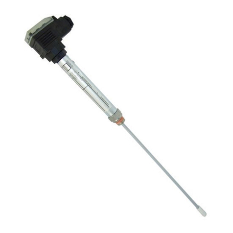
2LRGT 16-3n, 16-4n, 17-3n - Installation & Operating Manual - 850878-01
Contents
Content of this Manual................................................................................................................................... 4
Scope of delivery/Product package............................................................................................................... 4
How to use this Manual.................................................................................................................................. 5
Illustrations and symbols used...................................................................................................................... 5
Hazard symbols in this Manual...................................................................................................................... 5
Types of warning ............................................................................................................................................ 6
Specialist terms / Abbreviations.................................................................................................................... 7
Usage for the intended purpose..................................................................................................................... 7
Improper use .................................................................................................................................................. 8
Basic safety information ................................................................................................................................ 9
Required personnel qualifications............................................................................................................... 10
Notes on product liability............................................................................................................................. 10
Function ........................................................................................................................................................ 11
Technical data .............................................................................................................................................. 13
Example name plate/identification.............................................................................................................. 16
Factory settings............................................................................................................................................ 19
Measuring ranges of the LRGT 1x-3n based on the setting of the “Sout” parameter................................. 19
Overall view .................................................................................................................................................. 20
LRGT 16-3n............................................................................................................................................. 20
LRGT 16-4n............................................................................................................................................. 20
LRGT 17-3n............................................................................................................................................. 20
Dimensions of the LRGT 16-3n .................................................................................................................... 22
Dimensions of the LRGT 16-4n .................................................................................................................... 23
Dimensions of the LRGT 17-3n .................................................................................................................... 24
Installation.................................................................................................................................................... 25
Additional notes for installation ................................................................................................................ 26
Example LRGT 16-3n............................................................................................................................... 27
Installation examples with dimensions....................................................................................................... 29
Conductivity measurement ...................................................................................................................... 29
Conductivity monitoring and continuous blowdown control ...................................................................... 30
Conductivity monitoring and continuous blowdown control via a separate level pot.................................. 31
Key Fig. 11 to Fig. 13 ............................................................................................................................... 32
Aligning the terminal box............................................................................................................................. 32
Functional elements............................................................................................................................. 33

