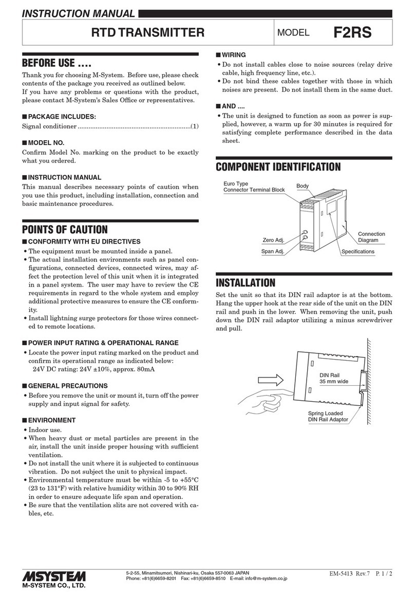
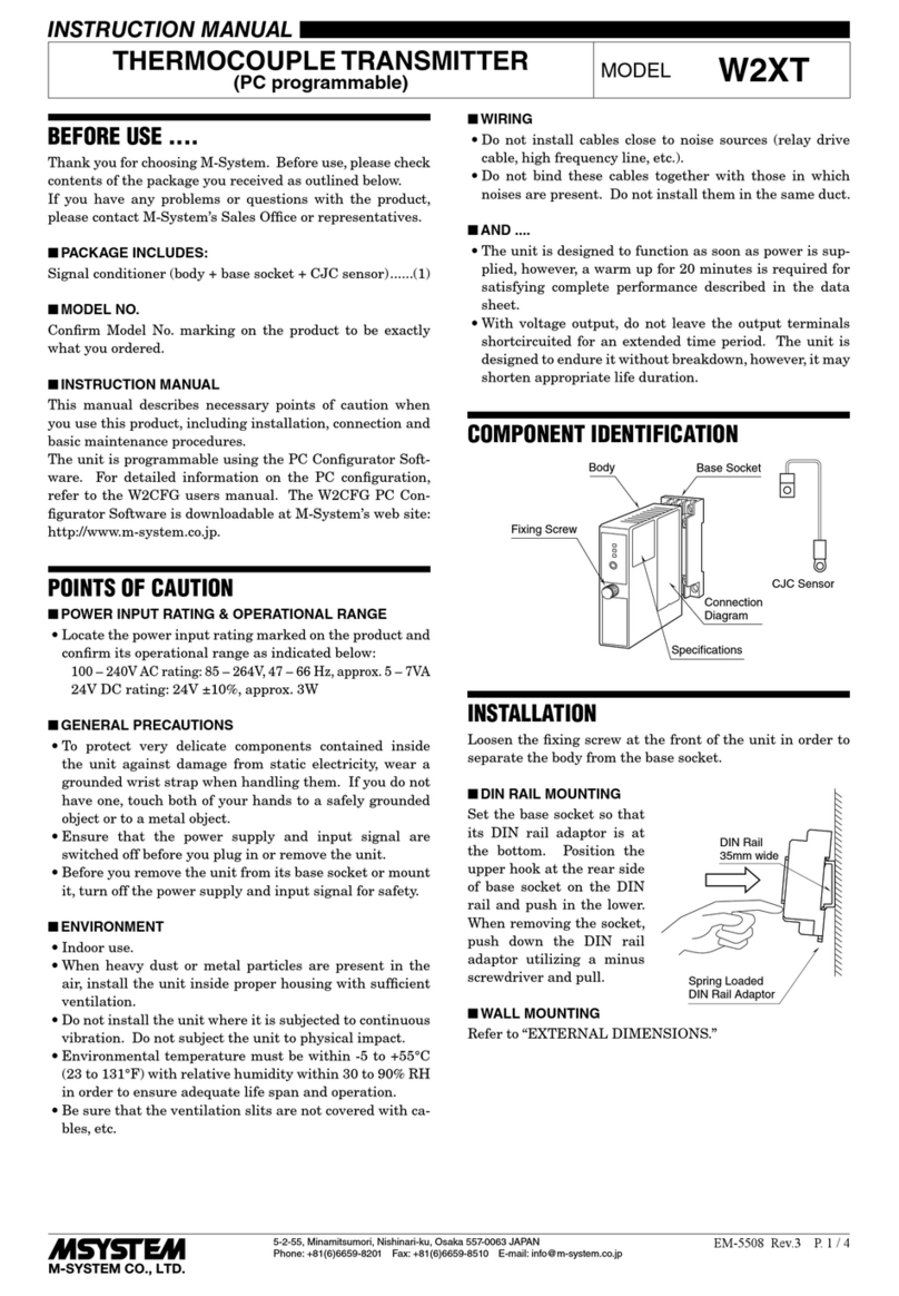
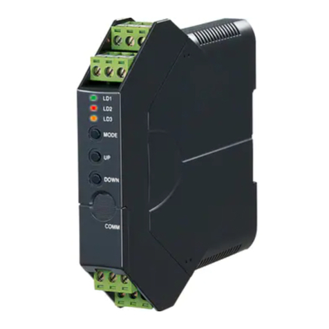
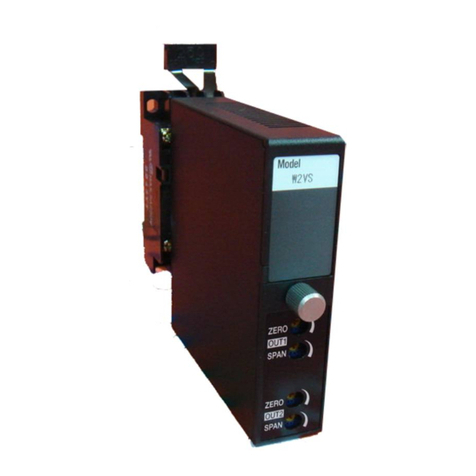
manuals.online logo
Brands
  1. Home
  2. •
  3. Brands
  4. •
  5. M-system
  6. •
  7. Transmitter
  8. •
  9. M-system B3HU2 User manual

M-system B3HU2 User manual

5-2-55, Minamitsumori, Nishinari-ku, Osaka 557-0063 JAPAN
Phone: +81(6)6659-8201 Fax: +81(6)6659-8510 E-mail: info@m-system.co.jp
EM-7501-A Rev.2 P. 1 / 3
INSTRUCTION MANUAL
2-WIRE UNIVERSAL TEMPERATURE TRANSMITTER
(HART communication, low temp. drift) MODEL B3HU2
BEFORE USE ....
Thank you for choosing M-System. Before use, please check
contents of the package you received as outlined below.
If you have any problems or questions with the product,
please contact M-System’s Sales Office or representatives.
■PACKAGE INCLUDES:
Signal conditioner ...............................................................(1)
I/O range and tag name label sheet ...................................(1)
■MODEL NO.
Confirm Model No. marking on the product to be exactly
what you ordered.
■INSTRUCTION MANUAL
This manual describes necessary points of caution when
you use this product, including installation, connection and
basic maintenance procedures.
POINTS OF CAUTION
■CONFORMITY WITH EU DIRECTIVES
•Functional insulation is maintained between the input
and output.
•The equipment must be mounted inside a panel.
•The actual installation environments such as panel con-
figurations, connected devices, connected wires, may af-
fect the protection level of this unit when it is integrated
in a panel system. The user may have to review the CE
requirements in regard to the whole system and employ
additional protective measures to ensure the CE conform-
ity.
•Install lightning surge protectors for those wires connect-
ed to remote locations.
■GENERAL PRECAUTION
•Before you remove the unit or mount it, turn off the power
supply and input signal for safety.
■ENVIRONMENT
•Indoor use.
•When heavy dust or metal particles are present in the
air, install the unit inside proper housing with sufficient
ventilation.
•Do not install the unit where it is subjected to continuous
vibration. Do not subject the unit to physical impact.
•Environmental temperature must be within -40 to +85°C
(-40 to +185°F) with relative humidity within 0 to 95%
RH in order to ensure adequate life span and operation.
•Be sure that the ventilation slits are not covered with ca-
bles, etc.
■WIRING
•Do not install cables close to noise sources (relay drive
cable, high frequency line, etc.).
•Do not bind these cables together with those in which
noises are present. Do not install them in the same duct.
■AND ....
•The unit is designed to function as soon as power is sup-
plied, however, a warm up for 10 minutes is required for
satisfying complete performance described in the data
sheet.
COMPONENT IDENTIFICATION
Body
Specifications
(side)
■HOW TO SEPARATE THE EURO TYPE CONNECTOR
TERMINAL BLOCKS
When you need to separate the euro type connector termi-
nal blocks from the transmitter body for wiring, insert a mi-
nus driver between the euro type connector terminal block
and the housing body, pull up the driver and pull out the
euro type connector terminal block.
INSTALLATION
■DIN RAIL MOUNTING
Set the unit so that its DIN rail adaptor is at the bottom.
Position the upper hook at the rear side of the unit on the
DIN rail and push in the lower. When removing the unit,
push down the DIN rail adaptor utilizing a minus screw-
driver and pull.
DIN Rail
35mm wide
Spring Loaded
DIN Rail Adaptor

B3HU2
5-2-55, Minamitsumori, Nishinari-ku, Osaka 557-0063 JAPAN
Phone: +81(6)6659-8201 Fax: +81(6)6659-8510 E-mail: info@m-system.co.jp
EM-7501-A Rev.2 P. 2 / 3
TERMINAL CONNECTIONS
Connect the unit as in the diagram below or refer to the connection diagram on the side of the unit.
■EXTERNAL DIMENSIONS unit: mm (inch)
10 11 12
456
123
789
106 (4.17)
18 (.71) 110.5 (4.35)
62 (2.44)
[5 (.20)]
DIN RAIL
35mm wide
• When mounting, no extra space is needed between units.
■CONNECTION DIAGRAM
1
4
2
3
T/C dual input
7
8
+
–
LOAD
OUTPUT
24 V DC
4 – 20 mA DC
+
–
+
–
* Limited to 250 – 1100 Ω for HART communication.
*
Voltage
A
A
B
B
RTD & Resistance
4-wire T/C3-wire2-wire
A
B
B
A
B
+
+
–
+
–
■WIRING INSTRUCTIONS
•Applicable wire size
Solid: 0.2 to 2.5 mm2(0.55 to 1.75 dia.)
Stranded: 0.2 to 2.5 mm2(Tinning wire ends may cause
contact failure and therefore is not recom-
mended.)
Ferruled: 0.2 to 1.5 mm2(0.55 to 1.35 dia.)
The following Phoenix Contact terminals are
recommended:
AI 0,25-8YE 0.2 to 0.25 mm2
AI 0,34-8TQ 0.25 to 0.34 mm2
AI 0,5-8WH 0.34 to 0.5 mm2
AI 0,75-8GY 0.5 to 0.75 mm2
AI 1,0-8RD 0.75 to 1.0 mm2
AI 1,5-8BK 1.0 to 1.5 mm2
•Expose wire conductors by 8 mm (0.31”).
8 mm 8 mm
4 mm dia.
max.
4 mm dia.
max.
Wire exposure Recommended
ferruled wire
B3HU2
5-2-55, Minamitsumori, Nishinari-ku, Osaka 557-0063 JAPAN
Phone: +81(6)6659-8201 Fax: +81(6)6659-8510 E-mail: info@m-system.co.jp
EM-7501-A Rev.2 P. 3 / 3
CHECKING
1) Terminal wiring: Check that all cables are correctly con-
nected according to the connection diagram.
2) Input: Check that the input voltage is within 0 – 100% of
full-scale.
If the thermocouple/RTD or its extension wires are bro-
ken, the output goes over 100% (below 0% with down-
scale) due to the burnout function. Check leadwires in
such a case.
3) Output: Check that the load is within the permissible
limit including wiring resistance.
Load Resistance (Ω) = Supply Voltage (V) – 9 (V)
0.023 (A)
(including leadwire resistance)
ADJUSTMENT PROCEDURE
■INPUT RANGE LABEL
Blank I/O range labels are included in the product package.
Write in the configured ranges and put the label on the side
as shown below.
INPUT
OUTPUT
I/O Range Label (included in the product package)
■PC CONFIGURATOR SOFTWARE
To calibrate the signal to match with a receiving instrument
or to change the factory-set configurations, use the PC Con-
figurator software installed on a Windows PC via a HART
modem connected to the PC.
The PC Configurator software is downloadable at M-Sys-
tem’s web site: http://www.m-system.co.jp
■USING THE HART COMMUNICATION
Refer to the HART Setup Manual (EM-7501-B) for setting
up the unit using the HHC. For operating an HHC (Hand-
Held Communicator), refer to its instruction manual.
LIGHTNING SURGE PROTECTION
M-System offers a series of lightning surge protector for
protection against induced lightning surges. Please contact
M-System to choose appropriate models.

Other M-system Transmitter manuals

M-system B3VS/2 User manual

M-system

M-system B3VS/2 User manual

M-system 10JR User manual

M-system

M-system 10JR User manual

M-system M5CT-5AM User manual

M-system

M-system M5CT-5AM User manual

M-system M3SXR User manual

M-system

M-system M3SXR User manual

M-system FSP User manual

M-system

M-system FSP User manual

M-system KCNA User manual

M-system

M-system KCNA User manual

M-system M2LR User manual

M-system

M-system M2LR User manual

M-system M6DVF User manual

M-system

M-system M6DVF User manual

M-system Mini-M M2RT User manual

M-system

M-system Mini-M M2RT User manual

M-system Mini-M M2CEC User manual

M-system

M-system Mini-M M2CEC User manual

M-system W2XM User manual

M-system

M-system W2XM User manual

M-system F2RS User manual

M-system

M-system F2RS User manual

M-system 10VF2 User manual

M-system

M-system 10VF2 User manual

M-system M5XU-1-R User manual

M-system

M-system M5XU-1-R User manual

M-system W2RS1 User manual

M-system

M-system W2RS1 User manual

M-system M3LV User manual

M-system

M-system M3LV User manual

M-system M3LM User manual

M-system

M-system M3LM User manual

M-system MXLC User manual

M-system

M-system MXLC User manual

M-system W2VS User manual

M-system

M-system W2VS User manual

M-system W2CFG User manual

M-system

M-system W2CFG User manual

M-system Mini-M M2WVS User manual

M-system

M-system Mini-M M2WVS User manual

M-system 18KJV User manual

M-system

M-system 18KJV User manual

M-system M5VF User manual

M-system

M-system M5VF User manual

M-system B3FV User manual

M-system

M-system B3FV User manual

Popular Transmitter manuals by other brands

halstrup-walcher PS17 instruction manual

halstrup-walcher

halstrup-walcher PS17 instruction manual

Monacor AV-5820TX Mounting instructions

Monacor

Monacor AV-5820TX Mounting instructions

BWI Eagle AIR-EAGLE SR Product information bulletin

BWI Eagle

BWI Eagle AIR-EAGLE SR Product information bulletin

AMX TX-MLCD Dimensional drawing

AMX

AMX TX-MLCD Dimensional drawing

Viatran 510 Installation data manual

Viatran

Viatran 510 Installation data manual

Televes 237301 Product description

Televes

Televes 237301 Product description

YOKOGAWA EJX Series user manual

YOKOGAWA

YOKOGAWA EJX Series user manual

Atlona AT-HDTX user manual

Atlona

Atlona AT-HDTX user manual

Absolute Process Instruments DuoPak APD 2015 instructions

Absolute Process Instruments

Absolute Process Instruments DuoPak APD 2015 instructions

Cypress CA-COMPAT Operation manual

Cypress

Cypress CA-COMPAT Operation manual

Ameri-King AK-451 Series Installation and operation manual

Ameri-King

Ameri-King AK-451 Series Installation and operation manual

BWI Eagle AIR-EAGLE SR PLUS Product information bulletin

BWI Eagle

BWI Eagle AIR-EAGLE SR PLUS Product information bulletin

Baker Hughes Panametrics DigitalFlow XGM868i Startup guide

Baker Hughes

Baker Hughes Panametrics DigitalFlow XGM868i Startup guide

Invisible QC0144 installation manual

Invisible

Invisible QC0144 installation manual

Honeywell 5834 Installation and setup guide

Honeywell

Honeywell 5834 Installation and setup guide

Honeywell 5834-4 Series Installation and setup guide

Honeywell

Honeywell 5834-4 Series Installation and setup guide

R.V.R. Electronica AUD2MP1 user manual

R.V.R. Electronica

R.V.R. Electronica AUD2MP1 user manual

MuxLab 500777-TX Quick installation guide

MuxLab

MuxLab 500777-TX Quick installation guide

manuals.online logo
manuals.online logoBrands
  • About & Mission
  • Contact us
  • Privacy Policy
  • Terms and Conditions

Copyright 2025 Manuals.Online. All Rights Reserved.