BackStopper CA-5030 User manual

INSTALLATIONINSTRUCTIONS:
The CA-5030 isanultrasonicparking assistsystemdesignedforuseonthe rearbumperof
mostcarsandtrucks.Thissystemdetectsanypeopleorobjectsbehindthevehicleusing (4)
ultrasonicsensorsthataremounted intherearbumperaswell asgiving you afull viewbehind
thevehiclewitha170°CMOScolorcamera.Thedistancedisplayandtheimagearedisplayed
ona3.5”LCD colormonitor
FEATURES:
•(4)Ultrasonicsensorswithquickdisconnectwaterproofconnectors
•(1)170°CMOScolorcamera
•(1)3.5”ultra-thincolorLCD monitor
•Separateaudiblebuzzerwithmultipletonestowarndriverofobstruction
•Cameraautomaticallyswitchesonwhenvehicleisshifted intoreverse
•Audibleandvisualalerts
•4-Stagesimulationbarsfordistanceread-outonthemonitor
•Shallowverticalsensing are(Sensorscan bemounted onvehiclesthathavelower
bumpersorbodykits)
•Sensorscanbepainted tomatchthecolorofthevehicle
•Specialmetalbumpersensors(MBS)availablefortrucksthathavemetalbumpers
•Includesholesawbitsand3Mtapeforinstallation

INSTALLATION
INSTALLING THESENSORS
TheCA-5030canbe installed with(2)sensorsor(4)sensorson therearbumperofthe
vehicle.(4)Sensorsarerecommended forthe bestcoveragebehindthevehicle.
1. Measureoutthedistanceacross thebumperandtrytospacethesensorsequallyapart.
Spacethesensorsatleast1-1.5feetapartfromeachotherifyouareinstalling (4)
sensorsand2-2.5feetapartfromeachotherifyouareinstalling (2)sensors.Theheight
ofthesensorsshouldbeatleast1.5–2.5feetfromthegroundtothesensorbutnoless
than1.5feet. (SeeFIGURE1) Ifyourmeasurementscomeinalittleoverthe specified
heightorwidththanthat’sfinejustaslong asthesensorsarenotspacetooclose
togetherortoo closetotheground.
2. Fortruckswithunevenbumperspacesuchaspick-up truckswithacentersteporand
licenseplateinthe middle,youcanspacethesensorsevenlyonbothsideofthecenter
stepinthebumper. (See FIGURE2) Sometruckbumpersmaybealittlehigherthan2.5
feet. Thisisnotaproblemandwill notinhibitthesystemfromworking.Thekitcomes
included withplasticmounting shimswhichwill anglethesensorsdownalittlebitifyou
havetomountthemhigherup onthebumper.Fortruckswithmetalbumpers,we
recommendusing akitcalled theCA-5030.MBS.Thissystemistheexactsamebut
comeswithsensorsspecificallydesignedforusewithmetalbumpers.
NOTE: Usemasking tapeorelectricaltapetomarkyourmeasurementsonthebumperfor
thesensors.Makesurethatyourmeasurementsarestraightall thewayacross thebumper
andthatthesensorshavebeen spacedevenlybeforeyoubegindrilling.
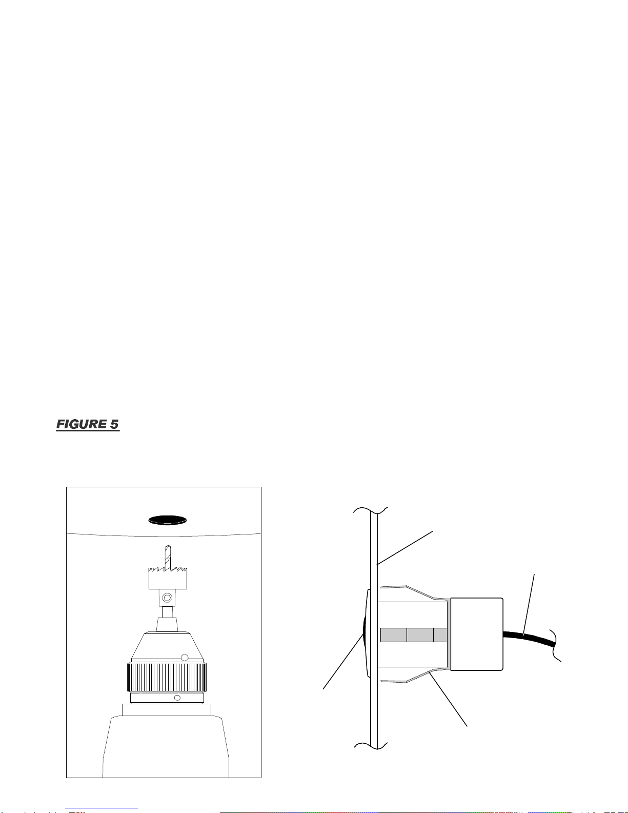
3. Usethe provided holesawbittodrill the holesinthebumper.Thisholesawbitshould
giveyou anadequatesized holetofitthesensorperfectly.Onceyouhavetheholes
drilled,routethesensorcablesthrough theholesandsnapthesensorsintoplace. (See
FIGURE3)
NOTE: Ifthesensorfitstoo tightlyintotheholethentrytodrill theholejustalittlebitwider
butnotwide enough towherethesensorisveryloose.Ifthesensoristoo tight, thesystem
maynotfunctionproperly.If the sensorisloose,DONOTapplyanykind ofadhesiveor
silicontoholditinplace.See ourtroubleshooting sectionformoredetails.
4. Whenplacing thesensorsintothebumper,itisimportanttonotehowtheyshouldfitinto
place.Alwaystrytoputthe sensorsonthe flattestpartofthe bumpersurfaceaiming
straightoutbehindthevehicle.Ifthesensorsareangleslightlydownwardonthebumper
thanthatisokayjustaslong astheyarenotangled extremelyup ordownindirection.If
thesensorsareangledtoofardownward,then theywill pickup theground the systemis
onandcausefalsewarnings.Ifthesensorsareangled too farupward,thentheywill not
pickup anything becausetheyareaiming atthesky andthiswill causethesystemtofail.
NOTE: Ifyourun intoan issueduring theinstall whereyouneedthesensorstobeangled
backup ordownorthebumpersurfaceisslightlycurved oruneven,thenyoucanusethe
providedplasticshimstoanglethe sensorsthe wayyouneedthemortocompensateforthe
unevenbumpersurface. (See FIGURE4)

CARBUMPERS
TRUCK BUMPERS
(2)SensorInstall (4)SensorInstall
2-2.5feet 1-1.5feet
1-1.5feet1 -1.5feet
Usetheprovidedholesawbittodrillsensorholes
Bumper
Sensor
Sensor Shim
SENSOR DIRECTION
Installthe sensorsontoaflatbumpersurface.Makesurethatthe angleisnottooextremeupordown.Ifthe angleistoo
extreme,thesensorsmaynotworkcorrectly.Ifyouneedtoanglethe senosorsback upordownoryouhaveacurved
bumpersurface,pleaseusetheprovidedplasticshimstoadjusttheangle
Flat
Bumper Curved
Bumper
Curved
Bumper
Routethesensorcablesthroughtheholeandsnap
thesensorintoplaceonthebumper
GOOD NOT
GOOD NOT
GOOD GOOD
1.5-2.5feet
(Height)
(Width)(Width)
1.5-2.5feet
(Height)
(Width)(Width)

INSTALLATION
INSTALLINGTHECAMERA
1. TherearviewCMOScamerausesa170°wide-anglelensforbestall around
performance.The Camerawill displaythefull widthofmostparking spacesup to7feet
orevenwider.
2. Thecameraisdesignedtobeflushmounted onvehicle’ssurface.Itcanbemounted
anywhereonthevehiclethathasaflatsurface.Doublecheckbehind the surfaceof
whereyouwill bemounting thecameratomakesurethatthereisadequatespaceforthe
cameratobeplaced inthedecided location.
3. Usetheprovided HoleSawbittodrill theholeinthelocationyouhavechosenfor
mounting thecamera. (See FIGURE5)
WARNING:Whendrilling the hole,becarefulnottouseexcessiveforcewhenpushing
onthe drill asthebitmaybreakthrough the surfacequicklyand puncture
anything behinditresulting indamagetoanymodulesorOEMpartsbehind
themounting location.
4. Oncetheholehasbeen drilled,routetheRCAandPowercablesthrough theholeand
snapthe cameraintoplace.Thesteellocktabswill holdthecameratighttothemounting
surface. (See FIGURE5)
Mounting Clip
UsetheProvidedHoleSaw
BittoDrill theHolefortheCamera
Camera
Lens
Cable
Mounting
Surface

INSTALLATION
INSTALLINGTHESENSORCABLES
1. Routethecablesintothe trunkpanelsofthe vehicleeitherbydrilling and holeorusing a
pre-existing rubbergrommet. Ifyouhavethedrill ahole,makesuretosealtheholeonce
theinstallationiscompletetopreventleaksandkeepoutanyotherweatherelements. If
installing onatruck,routethecablesunderneaththebed ofthetruck.Pleasemakesure
toavoidanymoving partslikethesuspensionoraxels.Youmaybeabletolocatea
factorywireharnessthatyoucanzip-tiethecablestoandroutethemthewholelengthof
thetruckfollowing the factorywireharness.
2. Zip-tiethesensorcablestogetheralong withthecameravideocableand run themdown
thelengthofthe vehicle. (See FIGURE6)
NOTE: Trytoavoidrunning thesensorcablesnexttoanyhigh-currentpowerwiresor
electricaldevicesinthevehicleasthismaycausefalsesensorwarningsduring operation of
thesystem.
INSTALLINGTHECONTROLMODULE
1. Mountthecontrolmoduleunderthevehicledashboardorbehindthetrunkpanelsinthe
rearofthe carsomewhereoutofthe way.Usethesupplied 3Mdoublesidetape and
stickthemoduledowntothesurface. (See FIGURE7) Makesuretoclean anydustor
dirtfromthemounting surfacebeforeapplying thetape.
NOTE: Someinstallersprefertomountthecontrolmoduleinthetrunkpanelsinsteadof
underneaththedashboard.Thisisokaytodo,butpleasemakesurethatthemoduleisclear
ofanymoistureorexcessivevibrationinthetrunk.Ifinstalling themoduleunderthedash,
pleasemakesuretokeepitclearof anymoving partssuchasthesteering columnorpedals.
Thiswayyoucanavoidgetting the sensor,buzzer,cameraandmonitorcablescaughtor
pinched aftertheinstallationiscomplete.
2. Connectthesensorcablesintothecontrolmodule.Thesensorportsonthemoduleare
labeled A,B,CandDwhichcorrespondstothesensorswhicharealsomarked A,B,C
andD.Pleasemakesuretoplug inthecorrectsensortothecorresponding sensorport.
INSTALLINGTHEMONITOR&BUZZER
1. Usetheprovided 3Mdoublesided tapetomounttheMonitorandBuzzerinthevehicle.
(See FIGURE8&9) Youcanmountthe monitoralmostanywhereonthe vehicledash
board,centerconsoleorevenonthewindshield.Thebuzzercanbemounted ontheA-
Pillaroronthe backsideoftherearviewmirror.Oncethelocationsareset,routethe
cablesfromthebuzzerandmonitortothe controlmodule.
2. Thereisavolumeadjustmentonthe side ofthebuzzerthatallowsyoutoturnthesound
toahigherorlowertoneoryoucan alsoturnitcompletelyoff. (See FIGURE10) The
OFF setting isnormallyused ifyouhaveatrailerhooked up tothe vehicleanddon’twant
thebuzzertosoundconstantlywhenthevehicleisinreverse.
Table of contents