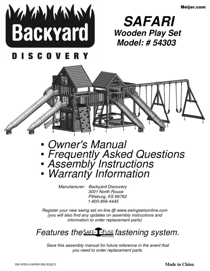
Backyard Brookdale 2006522B User manual

12
x
10
BROOKDALE
MANUFACTURED
BY:
Backyard
GAZEBO
WITH
ELECTRIC
Backyard
Discovery
3305
Airport
Drive
Pittsburg,
KS
66762
DISCOVERY
Model
#
2006522
Owner's
Manual
&
Assembly
Instructions
800-856-4445
•
,
•
•
.
q
.•
•
—.wok
Wer
•
•
\
•
r
I
0
average
2
person
assembly
time
Before
you
begin
))
GOCONFIGURE
F
UIC
INSTALLATION1
. 4 4
itM
D,
EASY
ASSEMBLY
SERVICES
1.
FIND
3D
INSTRUCTIONS
AVAILABLE!*
FOR
THIS
PRODUCT
IN
Need
a
helping
hand?
BILL
Let
our
team
of
professionals
handle
the
installation
for
you!
a9
Ouck
s
G0C0NFIGURE
DOWNLOAD
THE
FREE
APP
888-888-5424
assembly
time
may
vary
based
on
skill
level
NO'
(
GOo
'
gle
Play
'Installation
services
are
only
available
to
U.S.
customers.
4 "
);VOZ
For
the
most
up
to date
assembly
manual,
to
register
your
set,
or
to
order
replacement
parts
please
visit
www.backyarddiscovery.com
SAVE
THIS
ASSEMBLY
MANUAL
FOR
FUTURE
REFERENCE
IN
THE
EVENT
THAT
YOU
NEED
TO
ORDER
REPLACEMENT
PARTS.
Para
obtener
instrucciones
en
espariol,
visite
www.backyarddiscovery.com
Made
in
China
INS-2006522-A-BROOKDALE-ENG
12/03/2019
Made in China
INS-2006522B-A-12x10 BROOKDALE GAZEBO ENG 11-5-2021
Manufactured by:
Backyard Discovery
3305 Airport Drive, Pittsburg, KS 66762
800-856-4445
EASY STEP-BY-STEP
3D INTERACTIVE INSTRUCTIONS
DOWNLOAD THE FREE APP
Basepoint Business Centre: Rivermead Drive,Westlea, Swindon SN5 7EX Phone: 0800-118-2476
J.P. Coenstraat 7, The Bridge, The Hague, 2595 WP, Netherlands Phone: 08005678990
12x10 Brookdale
Gazebo
MODEL # : 2006522B
Please visit www.backyarddiscovery.com
For the most up to date assembly manual, to re gister your product, or to order
replacement parts
Para obtener instrucciones en español, visite
www.backyarddiscovery.com
INSTALLATION
SERVICES
AVAILABLE!*
See inside
See inside
for
for det
details
ails

.......
Owner's
Manual
=
-
-=---
--
-
=
7,7=
= ;
-
-
7---
-
7-
2-
=-
It
is
critically
important
that
you
start
with
square
and
level
footings,
concrete
pad
or
deck
to
attach
your
structure
•
Pay
close
attention
to
the
items
needed
for
each
step.
Make
sure
you
are
using
the
correct
hardware
for
each
step.
Using
incorrect
hardware
may
result
in
improper
assembly
•
Remember
to
double
check
for
underground
utilities
and
overhead
electrical
lines
Post
mounts
are
provided
with
your
structure
which
allows
you
to
permanently
install
your
structure
to
a
pre-existing
or
new
wood
or
concrete
surface.
•
The
hardware
to
attach
the
post
mounts
to
the
structure
is
included.
•
The
hardware
to
mount
the
structure
permanently
to
a
concrete
surface
is
included.
•
The
hardware
to
mount
the
structure
permanently
to
a
wood
deck
is
NOT
included
and
will
need
to
be
purchased
separately.
You
must
ensure
there
is
ample
structural
support
under
the
deck
before
permanently
attaching.
Metal
Roof
Assembly
Remove
plastic
covering
from
metal
roof
panels
before
installing
each
piece.
Place
roofi
ng
materials
on
a
nonabrasive,
flat
surface
before
and
after
assembly
as
it
could
bend,
dent
or
scratch
,,
--
-
--
---
--
-..
12'-1"
...-
-
_--
[3683
mm]
///// /////,
/
/
4
0
-....„,,,,,
N
IIIIIIIIII
.
4i
.__
7
__-___
I,
.=_
-
___- '=•-•
,
.
-.
„
.
1
fi
fi
1
/4/;//,';,9,-
11'-2
3/16"
15'-8
3/16"
10-0"
0
[3408
mm]
[4781
mm]
[3048
mm]
W
V ,
I
N
-
I
____4.
, I
I
fi
fi
9'
...
12'-1"
...-
[3683
mm]
I
.
- I
10'-4
1/8"
....
8'-9
3/16"
-...
9'-9
3/16"
[3153
mm]
...-
[2672
mm]
[2976
mm]
7'-4
3/8"
[2245
mm]
a'
9'-9
3/16"
-..
10'-9
1/8"
..-
[2976
mm]
.
I
[3280
mm]
I
TI
10
Owner's Manual Basic Setup Dimensions & Assembly Notes
•Pay close attention to the items needed for each step. Make sure you are using the correct hardware for each step.
Using incorrect hardware may result in improper assembly
•Remember to double check for underground utilities and overhead electrical lines
Post mounts are provided with your structure which allows you to permanently install your structure to a
pre-existing or new wood or concrete surface. See Anchor Instructions for further details and recommendations.
•The hardware to attach the post mounts to the structure is included.
•The hardware to mount the structure permanently to a concrete surface is included.
•The hardware to mount the structure permanently to a wood deck is NOT included and will need to be purchased
separately. You must ensure there is ample structural support under the deck before permanently attaching.
It is critically important that you start with square and level footings, concrete pad or deck to
attach your structure
2

Owner's Manual Anchoring Layout
10'-3 1/8"
[3.1 m]
10'-9 3/8"
[3.3 m]
9'-8 7/8"
[3 m]
9'-9 3/8"
[3 m]
9'-3 1/8"
[2.8 m]
8'-9"
[2.7 m]
13'-97/8"
[4.2m]
FOOTCENTERTOFOOTCENTER
13'-11/2"
[4m]
FOOTCORNERTOFOOTCORNER
3 3/8 in
[86 mm]
3 3/8 in
[86 mm]
1 3/4 in
[43 mm]
1 3/4 in
[43 mm]
(4) ANCHORS PER POST
3

Owner's Manual Parts Identification
Wood Components (Not to Scale)
ANGLE BRACE - W2A02967
1 5/16"x6 7/16"x35 3/4" (34x163x908)
AB1
(8)
BEAM - W4L13079
1 3/8"x5 1/4"x111 1/8" (36x134x2824)
D1
(2)
BEAM - W4L13080
1 3/8"x5 1/4"x64 5/8" (36x134x1640)
D2
(8)
BEAM - W4L13072
1 3/8"x5 1/4"x11 1/2" (36x134x292)
D3
(4)
BEAM - W4L13075
1 3/8"x5 1/4"x102 3/8" (36x134x2600)
D4
(2)
ANGLE BRACE - W4L13071
1 3/8"x5 1/4"x30 1/4" (36x134x769)
D6
(4)
ANGLE BRACE - W4L13082
1 3/8"x5 1/4"x32 3/8" (36x134x823)
D7
(4)
OUTSIDE RAFTER - W4L13076
1 3/8"x3 3/8"x77 3/8" (36x86x1965)
E1
(4)
RAFTER - W4L13073
1 3/8"x3 3/8"x77 3/8" (36x86x1965)
E2
(6)
ANGLE BRACE - W2A02968
1 5/16"x6 7/16"x35 3/4" (34x163x908)
AB2
(7)
ANGLE BRACE - W2A03470
1 5/16"x6 7/16"x35 3/4" (34x163x908)
AB3
(1)
4

Owner's Manual Parts Identification
Wood Components (Not to Scale)
SHEATHING BOARD - W4L13074
1 3/8"x3 3/8"x91 3/4" (36x86x2330)
E3
(8)
SHEATHING BOARD - W4L13081
1 3/8"x3 3/8"x27 1/4" (36x86x692)
E4
(8)
RAFTER - W4L13077
1"x3 3/8"x105 1/8" (24x86x2670)
H1
(2)
FASCIA - W4L13078
1"x3 3/8"x59 3/8" (24x86x1507)
H2
(4)
END RAFTER - W2A02962
2 13/16"x5 1/4"x80 5/8" (72x134x2048)
RP1
(2)
POST - W2A02963
6"x6"x92 1/16" (152x152x2338)
P1
(2)
POST - W2A02965
7"x7"x32 1/2" (152x152x845)
P3
(2)
END RAFTER - W2A02966
2 13/16"x5"x80 5/8" (72x134x2048)
RP2
(2)
POST - W2A02964
6"x6"x92 1/16" (152x152x2338)
P2
(2)
RIDGE CAP STIFFENER - W4L13590
1"x2 3/8"x47 5/8" (24x60x1210)
J9
(2)
RIDGE CAP STIFFENER - W4L13591
1"x2 3/8"x69 1/4" (24x60x1760)
J10
(2)
5

........
6-6e6-
Owner
'
s
Manual
........,.
__
,,,
:_7,.-_
_.
=:=T__
........,-:„-,.
• • •
,..
„
r
r
Hardware
Components
H
1008291
5
B
/
O
16
L
x
T
9
W
1/
H
2
BLK
ill ir
.4
(x4)
l '
.1
H1007651
BOLT
WH
5/16x8
BLK
(26)
78741
BOLT
WH
5/16x6
1/2
BLK
11
\T1T \1"
°
H100194
I
BOLT
WH
BLK
(x18)
5/16x2
1/2
H100193
NUT
BARREL
WH
BLK
(x42)
I5/16x1-1/2
H100205
I
BOLT
WH
BLK
(x42)
I
5/16x2-1/4
H100192
I
NUT
BARREL
WH
BLK
(x70)
I
5/16x7/8
H100407
I
BOLT
WH
BLK
H100379
IT
-NUT
BLK
(x13)
5/16x11/2
(x26)
I
5/16
H100459
BOLT
WH
BLK
H100206
1
LAG
SCREW
WH
5/16x3
BLK
I
(x
18
)
5/16x1
1/4
(22)
H100468
I
BOLT
WH
BLK
H100471
LAG
SCREW
WH
BLK
I
(x9)
I
5/
1
6x
1
(x54)
5/16x1
1/2
13
Owner's Manual Parts Identification
6

Owner's Manual Parts Identification
Hardware Components
SCREW PFH BLK
8x2-1/2
(x4)
H100201
SCREW PFH BLK
8x2
(x78)
H100391
SCREW PFH BLK
8x1 1/2
(x30)
H100200
SCREW PWH BLK
8x1 1/4
(x33)
H100536
WASHER LOCK EXT BLK
12x19
(x88)
H100199
WASHER LOCK EXT BLK
8x19
(x92)
H100198
WASHER FLAT BLK
8x19
(x17)
H100630
SCREW PWH BLK
8x3/4
(x17)
H100392
NUT LOCK BLK
5/16
(x4)
H100479
WASHER FLAT BLK
5/16
(x4)
H100770
SCREW WOODGRIP
10x3/4
(x17)
H100833
TORX BIT
T-40
(x1)
A100042
TORX WRENCH
T-40
(x1)
A100041
SCREW SETTER
(x1)
H100764
SCREW TAPPING
1/4x3/4
(x17)
H100759
SCREW WOODGRIP
10x1 1/4
(x132)
H100760
SCREW CONCRETE ANCHOR
1/4x2
(x18)
H100120
TORX BIT
T-30
(x1)
H100147
TORX WRENCH
T-30
(x1)
H100114
MAGNETIC DRIVER
(x1)
H101100
7

Owner's Manual
Accessory Components (Not to Scale)
Parts Identification
BYD ID TAG (SMALL) WITHOUT AGES
(x1)
A100241
ROOF BRACKET
(x6)
A4M00961
L BRACKET 66x66x127 - BLK
(x4)
A4M00619
BRACKET
(x4)
A4M00972 BRACKET
(x2)
A4M00973
BRACKET
(x4)
A4M00979
BRACKET
(x4)
A4M00974
8

• • 0
Ili
kk.
e
a
e
s
e
=
=
Owner's
Manual
_______
- -
a,
e
0• • •
,ic
,
Accessory
Components
(Not
to
Scale)
EE,
ED
.
POST
PLATE
A4M
(
x
0
8
0
)
978
I
A4M00977
(x8)
I
POST
ANCHORING
PLATE
1
11
lf
t
I
/ i
ill
°
i
_____,.
t.:-.
qp)
p).•
0
0"
'•-4.
!
,
,,
11e
A6P00308
I
6x6
POST
FOOT
(x4)
6.---
-111
0
0
'
6
11.0. li
e
A6P00265
I
ELECTRICAL
OUTLET
KIT
-
PATENT
PENDING
(
1
)
A6P00171
(x/)
I
STAIN
MARKER
16
Owner's Manual Parts Identification
9

Owner's
Manual
• • •
Accessory
Components
(Not
to
Scale)
A4M
0
)
1241
29
GA
STEEL
SHEETING
(x8
1
A4M
011161
RIDGE
CAP
29
GA
(x2)
A4M
0,
01
)
127
RIDGE
CAP
SPLICE
A6P00398
I
RIDGE
CAP
PROTECTOR
(x2)
A4IV(I
)?4
0)982
I
ROOF
EDGE
TRIM
00
)
983I
ROOF
EDGE
TRIM
SPLICE
A4M
(x
17
Owner's Manual Parts Identification
10

BOLT WH
5/16 x 2-1/2
H100194
(x2)
PRE-ASSEMBLY
It is critical for ease of assembly that you take the time to sort and organize the wood and
hardware.
WOOD PARTS:
•Organize wood parts by the three-digit, alpha-numeric number stamped on each board (ex. P01).
•If there are multiple boards with the same stamped number, stack those pieces together.
•Stamps can be found on the flat surface of the boards or on the end of the boards.
•Allow yourself plenty of room - the wood pieces can take up a significant amount of space.
HARDWARE PARTS:
•We recommend that you have a separate table to organize the hardware.
•Hardware bags are printed with a seven-digit, alpha-numeric part number.
•You can organize your hardware by part number or group by hardware type (i.e. bolts, nuts, etc.).
•During assembly you only need to reference the last four digits of the number.
NOTE: CARTONS ARE NOT ORGANIZED BY BOARD NUMBER.
STEP 1 - Sorting Parts
11

Square
Level 24"
Phillips Screw Driver
Open End
Wrenches 1/2" &
7/16"
Drill Attachments:
Phillips Head
Rubber Mallet -
Optional
Tape Measure Claw Hammer
1/8", 3/16", 3/8" &
7/16" Drill Bits
3/8" Drive Ratchet, 1/2" &
7/16" STD Sockets, 1/2" &
7/16" Deep Sockets
Cordless Drill or
Electric Drill
3/8 & 5/16" Nut Drivers
QUICK RELEASE
BAR CLAMP
A6P00460
(
2)
PRE-ASSEMBLY
STEP 2 - Tools Required
12

There are several types of assembly instructions available to you.
1.
Printed Assembly Manual included with your set
2.
BILT APP - 3D interactive instructions
3.
Combination of the Printed Manual and BILT APP (Note: Step numbers can differ between the two
methods)
PRE-ASSEMBLY
STEP 3 - Choose Your Assembly Method
13

•
•,„•„
•
•
.
•
Phase
STEP
1
••
•
•
•
•
.
000411
P1I
POST
-
W2A02963
(2)
6"x6"x92
1/16"
(152x152x2338)
rc
A6P00308
I
6x6
POST
FOOT
(X
4
)
H100200ISCREW
PFH
BLK
P2I
POST
-
W2A020610
(x16)
8x1
1/2
(2)
6"x6"x92
1/16"
(152x152x2338)
COMPLETE
THIS
STEP
TWICE
\v /
TIP:
FOR
EASE
OF
ASSEMBLY
WE
RECOMMEND
USING
SAW
HORSES
FOR
STEPS
1
THROUGH
3.
•
PI
(xv
POST
•
(
,\
308
(x2)
6x6
POST
FOOT
•.•..
200(x8)
SCREW
-
1
1/2"
P2
(xv
POST
18
Phase 1 STEP 1
14

•
•,.,••.,
•
.
•
•
•
•
Phase
1
STEP
2
•
•
•
•
.
•
2'-1"[636
mm]
--■
I
'l
00
6
PILOT
HOLE
:J? mei
UL
I
BEAM
-
W4L13080
A4M00619
I
L
BRACKET
66x66x127
-
BLK
,4'
'
DOWN
(x4)
(8)
1
3/8"x5
1/4"x64
5/8"
(36x134x1640)
°
"
0 0 0
0 0 0
A4M00972
I
BRACKET
P3
I
POST
-
W2A02965
(x
4
)
(2)
7"x7
.
5(32
1/2"
(152x152x845)
A4M00974
I
BRACKET
(x4)
I
--
H100765
BOLT
WH
BLK
(x24)
I
5/16x8
4
.
1111
0
H012040
)
I
1
93
5
7
1
6
T
x1-1
BARREL
/2
WH
BLK
H100471
x8)
1
5
L
/
A
1
G
6x1
C
1
7
2
EW
WH
BLK
H1
(
0
8
0
)
198W
8
WASHER
LOCK
EXT
BLK
(
NOTE:
-,
)
COMPLETE
THIS
STEP
TWICE
READ
ALL
THE
NOTES
BEFORE
(
YOU
BEGIN
EACH STEP.
)
.c.--
<
4
')-Z`
52-
FACE
HOLES
INWARD
.
P3
(xl)
ON
EACH
POST
.
D2
(xi)
POST
0
BEAM
•
.
.
(P1)
J.
D2
(x/)
.
BEAM
.
-
972
(x2)
BRACKET
D2
(xt)
o
471(x)
BEAM
LAG
SCREW
-
1
1/2"
- -
------
NOTE:
D2
(x7)
/
\
PILOT
HOLES
FACE
DOWN
BEAM
\
o
----
T
-
----„
,
193
0
a2
)
/
/
.
®°
NUT
BARREL
-
1
1/2"
,
(P2)
.
\
974(x2)
,
°
\
°
,
BRACKET
I
, /
.
.
-
I
.:
•%
.
/
198
(x4)
N
\F-__ ,„,
/
WASHER
-
8x19
,,
619
(x2)
---
-_
_
765
(x12)
L
BRACKET
BOLT
-
8"
19
Phase 1 STEP 2
FACE HOLES INWARD
ON EACH POST
PILOT HOLES
FACE DOWN
2'-1"
[636 mm]
BOTH
SIDES
15

COMPLETE THIS STEP TWICE
(USE (4) AB2 ANGLE BRACES FOR OTHER SIDE)
Phase 1 Ǣǻrƻˢ
ˡ˟ˤ
ʹɮ˧ʺ
Dŷĵǻ˚ˡˠˀˣ˃
ˠ˨˧
ʹɮ˧ʺ
ɟǢËrNJ˚˧ɮˠ˨
ˠ˨˨
ʹɮ˧ʺ
ɟǢËrNJ˚ˠˡɮˠ˨
ˠ˨ˡ
ʹɮ˧ʺ
ŗȕǻDNJNJrĵ˚˦ˀ˧˃
ANGLE BRACE - W2A02968
1 5/16"x6 7/16"x35 3/4" (34x163x908)
AB2
(7)
LAG SCREW WH BLK
5/16x3
(8)
H100206 BOLT WH BLK
5/16x2-1/4
(16)
H100205 NUT BARREL WH BLK
5/16x7/8
(16)
H100192
WASHER LOCK EXT BLK
12x19
(16)
H100199 WASHER LOCK EXT BLK
8x19
(24)
H100198
Dˢ
ʹɮˠʺ
ŗµĵrDNJNr
(ON ONE SIDE ONLY)
Dˡ
ʹɮˢʺ
ŗµĵrDNJNr
ˠ˨˧
ʹɮˣʺ
ɟǢËrNJ˚˧ɮˠ˨
ˡ˟˥
ʹɮˣʺ
ĵµǢNNJrɟ˚ˢ˃
ANGLE BRACE - W2A03470
1 5/16"x6 7/16"x35 3/4" (34x163x908)
AB3
(1)
16

• •
•
•
.
•
•
••
Phase
1
STEP
4
•
•
•
••
•
H100468
I
BOLT
WH
BLK
(x8)
5/16x1
D4
I
BEAM
-
W4L13075
(2)
1
3/8"x5
1/4"x102
3/8"
(36x134x2600)
H100192
NUT
BARREL
WH
BLK
H100199
WASHER
LOCK
EXT
BLK
I
(x8)
5/16
x
7/8
(x8)
I
12x19
•
199
(x8)
WASHER
-
12x19
192
(xs)
NUT
BARREL
-
7/8"
/
468(x8)
BOLT
WH
-
1"
•
.
•
D4
(xv
•
.
BEAM
•
•
;:
•
D4
(xi)
BEAM
• •
. .
•
00 00
•
.
21
Phase 1 Ǣǻrƻ4
TIPS:
• THREE PEOPLE ARE HELPFUL FOR THIS STEP.
• MOVE THE 10FT POST ASSEMBLIES TO THEIR FINAL LOCATION
WITH SOMEONE HOLDING EACH ASSEMBLY UPRIGHT.
• USING A THIRD PERSON, CONNECT THE BEAM TO THE POSTS
TO MAKE THE GAZEBO FRAME.
17

O
.
II
. •
a
gl
a.
a a a
•
-
.7=
=
_
e
5.
Phase
1
e
•
•
•
D1
I
BEAM
-
W4L13079
H100354
I
BOLT
WH
BLK
I
(x2)
1
3/8"x5
1/4"x111
1/8"
(36x134x2824)
(x16)
5/16x6
1/2
0 0
o
a
D3
BEAM
-
W4L13072
A4M00979
I
BRACKET
H100193
I
NUT
BARREL
WH
BLK
H100199
I
WASHER
LOCK
EXT
BLK
(x4)
1
3/8'X5
1/4'X11
1/2
(36x134x292)
(x4)
(x16)
5/16x1-1/2
(x16)
12x19
NOTE:
ALIGN
HOLES
IN
PLATE
WITH
HOLES
IN
D
1
&
D3
199(x16)
BOARDS
AND
MOUNT.
)
WASHER
-
12x19
-
N
N
193(x16)
NUT
BARREL
-
1
1/2"
0 0
®
'
D3
(xv
D3
(x/)
D1
(x7)-
°
BEAM
BEAM
BEAM
354(x16)
•
z
/
BOLT
-
6
1/2"
D1
(xo
9
79
(x4)
•
BEAM
BRACKET
•
•
•
•
•
•
;;
•
•
. .
D3
(xI)
Ol
BEAM
•
D3
(xi)
BEAM
.
.
.
.
22
Phase 1
Ǣǻrƻ5
ALIGN HOLES IN PLATE
WITH HOLES IN D1 AND
D3 BOARDS AND MOUNT.
18

• • •
•
.
•
•
•
•
Phase
1
STEP
6
•
•
••.•
••
H100205
BOLT
WH
BLK
4.1
`•
(x16)
I
5/16x2-1/4
H1001921
NUT
BARREL
WH
BLK
H1002061
LAG
SCREW
WH
BLK
(8)
I
5/16x3
AB1
I
ANGLE
BRACE
-
W2A02967
(x16)
I
5/16x7/8
(8)
1
5/16"x6
7/16'x35
3/4
(34x163x908)
H100198
WASHER
LOCK
EXT
BLK
H100199
I
WASHER
LOCK
EXT
BLK
I
(x24)
8x19
(x16)
I
12x19
199
(x
76)
192(x16)
WASHER
-
12x19
NUT
BARREL
-
7/8"
198(x16)
WASHER
-
8x19
205
(x76)
BOLT
-
2
1/4"
A
B
1
(x8)
ANGLE
BRACE
198(x8)
WASHER
-
8x19
206(x8)
LAG
SCREW
-
3"
I
-
•
°
•
.
•
.
•
23
Phase 1
Ǣǻrƻ6
CRITICAL: SQUARE UNIT BEFORE
PROCEEDING TO NEXT STEPS.
ONCE SQUARE, TIGHTEN ALL HARDWARE.
19

O. O. O.
g
liMlb.
•T•
r•
•T•
...
...
'
•
•
• —
e
g
e
Phase
1
_____
__-=
I , i
.d
P•
..
.,
———
S
•
i p,
L_P------.
• • •
•
Z
•
/
°
V
\_
:
°
----
'%_L\
\
. .
•
. .
•
RP1
I
END
RAFTER
-
W2A02962
RP2
I
END
RAFTER
-
W2A02966
D6
I
ANGLE
BRACE
-
W4L13071
(2)
12
13/16"x5
1/4"x80
5/8"
(72x134x2048)
(2)
I
2
13/16"x5"x80
5/8"
(72x134x2048)
(4)
1
3/8"x5
1/4"x30
1/4"
(36x134x769)
A4M
(x
0
2
0
)
973
I
BRACKET
I
MI IMI
H100206
LAG
SCREW
WH
BLK
H100194
BOLT
WH
BLK
H100407
BOLT
WH
BLK
(4)
I
5/16x3
(
8
)
I
5/16x2
1/2
(8)
I5/16x1
1/2
II
MII
IIIIII'
H100471
LAG
SCREW
WH
BLK
H100192
NUT
BARREL
WH
BLK
IIII
II.-
H100201
I
SCREW
2
PFH
BLK
I
(12)
5/16x1
1/2
(8)
I
5/16x7/8
(
4
)
I
0 0
H100199I
WASHER
LOCK
EXT
BLK
H100198I
WASHER
LOCK
EXT
BLK
M
100379
IT
-NUT
BLK
(
8
)
12x19
(4)
8
x
19
(
8
)
5/16
COMPLETE
THIS
STEP
ON
BOTH
SIDES
7
NOTE:
ALIGN
PILOT
HOLES
WITH
POST
HOLES
BY
1
TEMPORARILY
INSTALLING
THE
LONG
9-1/2"
\\,
BOLTS
H100829
BEFORE
INSTALLING
SCREWS.
/)
.--
o
cs17/
o
RP1(x)
END
RAFTER
. .
•
.
.
-
.
.
.
.
,
-
RP2(x1)
201
(x2)
\
.
.
•.,
•
.
END
RAFTER
---_
SCREW
-
2
1/2"
--,
-____
_
-----
- -
---„,,,
RP2(x1)
• •
END
RAFTER
D6
(x2)
•
:
.
ANGLE
BRACE
.•
'.(
,
o
192
(x4)
'
ANGLE
BRACE
.
•
•
,
NUT
BARREL
-
7/8
.
®
o
"
RP1(x))
.
,
o
\
199(x4)
END
RAFTER
__--
WASHER
-
12x19
,__
__--
194
(x4)
BOLT
-
2
1/2"
I
.
.•
,-----"
----_,
.--
z
/
198(x2)
,
WASHER
-
8x19
.
.
/
.
471(x4)
.
N
y
206(x2)
BRACKET
ASSEMBLY
LAG
SCREW
-
1
1/2"
LAG
SCREW
-
3"
973
(xi)
407(x4)
BRACKET
BOLT
-
1
1/2"
379(x4)
471(x2)
T
-NUT
-
5/16"
LAG
SCREW
-
1
1/2"
24
Phase 1
Ǣǻrƻ7
ALIGN PILOT HOLES WITH POST HOLES BY
TEMPORARILY INSTALLING THE LONG 9-1/2"
BOLTS H100829 BEFORE INSTALLING SCREWS
20
Table of contents
Other Backyard Outdoor Furnishing manuals
Popular Outdoor Furnishing manuals by other brands

Belson Outdoors
Belson Outdoors BST-01 instruction sheet

Outdoor Life Products
Outdoor Life Products Outdoor Living 6030-20F Assembly instructions

Diphano
Diphano Pure bench 280x40 instruction manual

CAZEBOO
CAZEBOO BAHIA 300S300 Assembly instructions

Allen + Roth
Allen + Roth LG-2156-LC-F Assembly instructions

Peg-Perego
Peg-Perego IGED1086 Use and care