2
TABLE OF CONTENTS
Introduction . . . . . . . . . . . . . . . . . . . . . . . . . . . . . . . . . . . . . 2
Installation . . . . . . . . . . . . . . . . . . . . . . . . . . . . . . . . . . . . . 2
Theory of Operation . . . . . . . . . . . . . . . . . . . . . . . . . . . . . . 5
Programming Software Installation . . . . . . . . . . . . . . . . . . . . 5
Wireless Receiver Programming . . . . . . . . . . . . . . . . . . . . 5
Wireless Sensor Programming . . . . . . . . . . . . . . . . . . . . . 7
Specifications . . . . . . . . . . . . . . . . . . . . . . . . . . . . . . . . . . . 8
INTRODUCTION
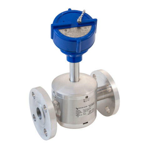
The Series 228PV wireless flow sensor system includes the
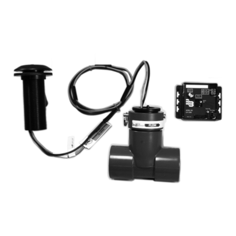
flow sensor mounted in a tee, radio frequency (RF) transmitter
complete with mounting kit, and RF receiver / pulse transmitter.
This system eliminates the need for expensive signal wires
from the sensor output. The battery powered flow sensor
performs flow measurement and scaling and then transmits a
total flow value to the RF transmitter. The transmitter sends an
RF signal approximately every four seconds that the RF re-
ceiver detects. The RF receiver compares the previous flow
total with the most recent flow total to generate a pulse output.
Using PC software, which is part of the software installation kit,
the pulse output can be scaled to represent the desired volume
unit and number of output pulses per unit volume that best fits
the application. Pulse width can also be adjusted to meet the
requirements of an interfacing control system or monitor.
Optional equipment offered with the 228PV wireless system
include two types of antenna kits and a software installation kit
complete with software and programming cables. Addition-
ally, DIN rail mounting clips are available. These accessories
can be ordered by specifying the appropriate model number
from the Sensor System Matrix.
Series 228PV Wireless Flow Sensor
The four-bladed impeller design is rugged, non-fouling and
does not require custom calibration. Coupled with the
proprietary patented digital detection circuit, the sensor
measures flow rate from 1 foot per second (fps) to over 20 fps
regardless of conductivity or turbidity of the liquid. The flow
sensor generates a frequency which is proportional to flow
rate. An integral micro controller measures the impeller
frequency and uses the appropriate K factor and offset values
to compute the flow rate. By means of integration, the volume
total is calculated. The output signal to the RF transmitter is a
scaled output pulse. An internal lithium battery provides power
for the flow sensor and is encapsulated to ensure moisture
resistance.
Wireless Badger®ORION RF Transmitter
The Badger ORION®transmitter operates in the 902-928 MHz
frequency band at a power level which requires no F.C.C.
licensing. The transmitter is powered using an internal lithium
battery and is encapsulated to ensure moisture resistance. It
is factory programmed and requires no configuration.
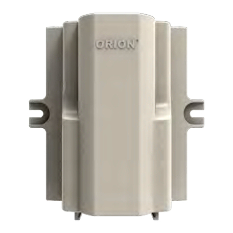
Wireless Badger ORION RF Receiver
The Badger ORION receiver is powered using an external
alternating current (AC) or direct current (DC) power supply.
The wireless receiver receives the scaled total from the
transmitter. Further scaling and unit conversion can be
programmed into the receiver. The optically coupled scaled
pulse output emulates a dry contact closure to ensure
interfacing into various types of controller inputs.
Exam
le: 2 28 PV 0 W - 1 2 3 1
Tee Mounted 28
PVC PV
1.5" 15
2" 20
3" 30
4" 40
0
ELECTRONICS
Wireless Transmitter and Receiver W
O-RING
EPDM 1
SHAFT
Tun
sten Carbide 2
IMPELLER
420 Stainless Steel 3
BEARING
UHMWPE
ultra-hi
h molecular wei
ht
ol
eth
lene
1
ELECTRONICS HOUSING
SIZE
MATERIAL
STYLE
Acetal Housing w/ Fortron Polyphenylene Tip
xx
ANTENNA
No Option
Low Profile Type A355LP Antenna
Whip Type A355 Antenna
MOUNTING
No Option
DIN Rail Mounting Clips
SOFTWARE INSTALLATION KIT
No Option
A301W-20 Cable, IR Cable, Software
0
1
2
XXX
0
1
0
1
Wireless Series 228PV Flow Sensor System Matrix
(1½" to 4")
INSTALLATION
General
As with all flow measuring devices accuracy is highly dependent
on proper location of the sensor in the piping system. Irregular
flow velocity profiles caused by valves, fittings, pipe bends, etc.
can lead to inaccurate overall flow rate indications even though
local flow velocity measurement may be accurate. A sensor
located in the pipe where it can be affected by air bubbles,
floating debris, or sediment may not achieve full accuracy and
could be damaged. Badger Meter flow sensors are designed
to operate reliably under adverse conditions, but the following
recommendations should be followed to ensure maximum
system accuracy:
1) Choose a location along the pipe with a length equivalent to
10 pipe diameters upstream and 5 pipe diameters
downstream of the sensor which are free of flow disturbances.
Pipe bends, valves, other fittings, pipe enlargements, and
reductions should not be present in this length of pipe.
2) When the sensor is installed in horizontal piping, the
preferred sensor orientation is vertical, on top of the pipe. If
trapped air or debris could potentially interfere with sensor
operation the sensor can be installed as much as 45
degrees from the vertical. Please note that when the sensor
is installed “off the vertical”, impeller friction increases which
may affect performance at low flow rates and increase wear.
The sensor should never be located at the bottom of the
pipe, as sediment may collect there. When the sensor is
installed in vertical piping, it can be installed at any
circumferential position. Rising flow is preferred to reduce
the effects of trapped air.

