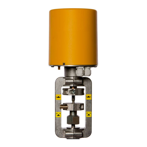
Baelz Automatic 373-E66 Series User manual

Page 1/37
Operating Instructions BA 373-E66
Technical specifications subject to change
W. Bälz & Sohn GmbH & Co. Koepffstrasse 5 74076 Heilbronn Germany
Observe copyright protection DIN 34
Baelz-electrodyn
Actuator for modulating duty
Motorized linear actuator baelz 373-E66
TA-MG 3515

Page 2/37
Operating Instructions BA 373-E66
Technical specifications subject to change
W. Bälz & Sohn GmbH & Co. Koepffstrasse 5 74076 Heilbronn Germany
Observe copyright protection DIN 34
Table of contents
1. SAFETY 4
1.1 Intended use ............................................................................................................................... 4
1.2 For the operator .......................................................................................................................... 4
1.3 Personnel .................................................................................................................................... 5
1.4 Before starting work .................................................................................................................... 5
1.5 During operation ......................................................................................................................... 5
1.5.1 Transport, installation and mounting ........................................................................................... 5
1.5.2 Service and maintenance ........................................................................................................... 5
1.6 Work environment ....................................................................................................................... 5
2. PRODUCT DESCRIPTION 6
2.1 Identication ................................................................................................................................ 6
2.2 Specications .............................................................................................................................. 6
2.3 Accessories and options ............................................................................................................. 7
2.4 Type name .................................................................................................................................. 7
2.5 Operating conditions ................................................................................................................... 8
3. TRANSPORT AND STORAGE 9
4. MOUNTING 9
4.1 Mounting position ........................................................................................................................ 9
4.2 Assembly with valve ................................................................................................................... 10
4.3 Operating principle ...................................................................................................................... 11
4.3.1 Manual adjustment ..................................................................................................................... 11
4.4 Removing the cover .................................................................................................................... 11
4.5 Electrical connection ................................................................................................................... 12
4.6 Making the electrical connection ................................................................................................. 12
5. COMMISSIONING 13
Attention ................................................................................................................................................ 13
5.1 Setting for switching off in end positions ..................................................................................... 13
5.2 Test run ....................................................................................................................................... 13
5.2.1 Checking the direction of rotation ............................................................................................... 13
5.2.2 Switching off in end positions ..................................................................................................... 13
6. ACCESSORIES 14
6.1 Switching and signalling unit ....................................................................................................... 14
6.2 Mounting and setting the switching and signalling unit ............................................................... 15
6.3 Setting a different travel .............................................................................................................. 16

Page 3/37
Operating Instructions BA 373-E66
Technical specifications subject to change
W. Bälz & Sohn GmbH & Co. Koepffstrasse 5 74076 Heilbronn Germany
Observe copyright protection DIN 34
6.4 Setting the potentiometer ............................................................................................................ 16
6.5 Setting the limit switches S3 and S4 ........................................................................................... 17
7. POSITIONING ELECTRONICS 18
7.1 Operating principle of the positioning electronics ....................................................................... 18
7.2 Mounting the positioning electronics ........................................................................................... 19
7.3 Electrical connection ................................................................................................................... 19
7.3.1 Terminal assignment ................................................................................................................... 20
7.3.2 Determining input and output signals ......................................................................................... 21
7.4 Commissioning and settings ....................................................................................................... 21
7.5 Calibrating the positioning electronics to the travel .................................................................... 23
7.5.1 Setting the zero ........................................................................................................................... 23
7.5.2 Setting the end position .............................................................................................................. 23
7.6 Setting the dead band ................................................................................................................. 23
7.7 Reversing the actuator action ..................................................................................................... 23
7.8 Detecting wire breaks ................................................................................................................. 24
7.9 Split range control ....................................................................................................................... 24
7.10 Changing the preset signal range for the set point ..................................................................... 25
7.11 Specications .............................................................................................................................. 26
8. ELECTRONIC POSITION TRANSMITTER "ESR" 27
8.1 Functional principle of the electronic position transmitter ........................................................... 27
8.2 Electronic position transmitter specications .............................................................................. 27
8.3 Electrical connection of the electronic position transmitter ......................................................... 28
8.4 Setting the electronic position transmitter ................................................................................... 29
8.4.1 Setting to Normal mode "N" ........................................................................................................ 29
8.4.2 Setting to Reverse mode "R" ...................................................................................................... 29
8.4.3 Adjusting the output current to 0 or 4 mA ................................................................................... 30
8.4.4 Adjusting the output current to 20 mA ......................................................................................... 30
9. HEATER 31
10. CONNECTION EXAMPLES 32
11. SPARE PARTS 33
12. DECOMMISSIONING AND DISPOSAL 34
13. TROUBLESHOOTING 34
13.1 Check list for operational malfunctions ....................................................................................... 35
14. DIMENSION SPECIFICATIONS 36

Page 4/37
Operating Instructions BA 373-E66
Technical specifications subject to change
W. Bälz & Sohn GmbH & Co. Koepffstrasse 5 74076 Heilbronn Germany
Observe copyright protection DIN 34
1. SAFETY
Carefully read the present Operating Instructions, especially the following safety precautions prior to installation
and operation.
Caution
Potentially hazardous situation which could result in minor injury.
Also indicates a risk which may cause material damage.
Attention
Potentially harmful situation which can result in damage to the product or an object in its
environment.
Danger
Imminently hazardous situation which will result in death or serious injury.
Warning
Potentially hazardous situation which may result in death or serious injury.
Tip: Instructions for use or other useful information.
1.1 Intended use
baelz 373-E66-150-22 motorized linear actuators are controlled by three-point control or constant control in combi-
nation with the PEL positioning electronics. The linear actuators of the series described in this manual are intended
for the adjustment of the valve stroke.
To ensure their intended use, make sure that the above type identication complies with the identication label of
the linear actuators before starting any activities. The actual technical data of the linear actuators and the power
supply requirements are the specications indicated on the identication label.
Any use other than the intended use mentioned above, different tasks, and operation with other power sources
than those permitted, is considered to be improper use. In case of improper use, the operator shall be solely liable
for the risk presented to persons and the device as well as other property!
The intended use also comprises compliance with the accident prevention regulations and the DIN VDE standards
of the German Institute for Standardization and the Association for Electrical, Electronic & Information Technolo-
gies. It also implies working in accordance with the safety requirements when performing all activities described in
the present Operating Instructions, under consideration of general technical rules and regulations.
1.2 For the operator
Make sure the Operating Instructions are kept permanently available and easily accessible at the site of operation
of the linear actuators!
During set-up, operation and when performing maintenance procedures on the device, observe the applicable oc-
cupational safety regulations, accident prevention regulations and the DIN VDE standards of the German Institute
for Standardization and the Association for Electrical, Electronic & Information Technologies. Observe compliance
with any possibly applicable additional regional, local or in-house safety regulations.
Make sure that any person assigned by you to perform the activities described in the present Operating Instruc-
tions, has read and understood these instructions.
Caution
Attention
Danger
Warning

Page 5/37
Operating Instructions BA 373-E66
Technical specifications subject to change
W. Bälz & Sohn GmbH & Co. Koepffstrasse 5 74076 Heilbronn Germany
Observe copyright protection DIN 34
1.3 Personnel
Only qualied personnel may operate these linear actuators or work in their vicinity. Qualied persons are persons
who are familiar with the set-up, installation, commissioning, operation and maintenance of the linear actuators
and possess the required qualication for their activity. The required or prescribed qualications include amongst
others:
● Training / instruction and the authorization to switch electric circuits and devices / systems on and off in
accordance with EN 60204 (DIN VDE 0100 / 0113) and the technical safety standards.
● Training or instruction in accordance with the technical safety standards for the maintenance and use of
appropriate safety equipment and personal protective equipment.
● First aid training.
Always work safely and never perform any work which might present a hazard to persons
or damage the linear actuator or other property in any way.
1.4 Before starting work
Prior to starting any kind of work, check if the types specied here are identical with the specications on
the identication label on the linear actuator:
baelz 373-E66-080-25 (8kN)
baelz 373-E66-150-22 (15kN)
1.5 During operation
Safe operation can only be ensured if transport, storage, assembly, operation and maintenance procedures are
performed in compliance with the safety requirements, and are performed properly and competently.
1.5.1 Transport, installation and mounting
Observe the general installation and safety regulations for heating, ventilating, air conditioning and piping. Use
tools properly and competently. Wear the required personal and other protective equipment.
1.5.2 Service and maintenance
Prior to maintenance or repair, make sure that the linear actuator is disconnected from power by qualied person-
nel in accordance with DIN VDE standards.
1.6 Work environment
Please observe the information regarding the work environment in the Specications.

Page 6/37
Operating Instructions BA 373-E66
Technical specifications subject to change
W. Bälz & Sohn GmbH & Co. Koepffstrasse 5 74076 Heilbronn Germany
Observe copyright protection DIN 34
2. PRODUCT DESCRIPTION
2.1 Identication
Each actuator has an identication label. This label includes specications regarding the maximum operating con-
ditions of the device and a unique, order-related serial number (F no.).
Figure 1: Baelz identication label for motorized actuators
2.2 Specications
Type Baelz 373-E66
Actuating force kN 8,0 15,0
Positioning speed 1) mm/min 25 22
Power consumption (230 V) VA 34
Nominal current (230 V) A 0.15
Type of motor 3) syn
Motor protection 4) B
Max. stroke mm 80
Supply voltages 2) 5) 24 V / 115 V / 230 V 50/60 Hz +-10%
Type of duty acc. to IEC 34-1 S4 – 30% ED 600 c/h
Cable gland 2 x M16x1.5 and 1 dummy plug
Electrical connection Inside terminal board, terminal assignment acc. to electrical connection diagram
Switch-off in end position 2 load-dependent switches, max. 250 V AC,
rating for resistive load, max. 10 A, for inductive load, max 5 A
Mounting position as desired, but not in downward position
Ambient temperature –20 °C to +60 °C
Lubricant for gearing Klüber Microlube GL 261 grease
Position indicator by anti-rotation xture
Manual adjustment with side-mounted handwheel
Enclosure protection acc. to EN 60529 IP 65
Trapezoidal thread Tr 20 x 4
Connection type DIN 3210 G0 (also refer to options)
Weight kg 13.0
1) at 60 Hz, the positioning speeds and input power increase by 20%
2) other supply voltages on request
3) syn synchronous motor
4) B stall proof motor
5) see price list for possible combina-
tions
Figure 2: Specications table

Page 7/37
Operating Instructions BA 373-E66
Technical specifications subject to change
W. Bälz & Sohn GmbH & Co. Koepffstrasse 5 74076 Heilbronn Germany
Observe copyright protection DIN 34
2.3 Accessories and options
2.4 Type name
Figure 4: Table - Options package 2
Options package 1 (continuous control)
2 WE 2 additional limit switches (S3 and S4) for signalling end positions or intermediate positions, freely
adjustable, max. 250 V AC, rating for resistive load max. 5 A, for inductive load max. 3 A
FG Potentiometer 1000 ohms, linearity error ≤ 0.5%, max. 1.5 W,
contact current 30 mA
PEL Positioning electronics for actuator control, input 0…10 V, 0 (4)…20 mA,
output 0…10 V, 0 (4)…20 mA, supply voltage 24, 115, 230 V 50/60 Hz,
requires 1000 ohm potentiometer.
HZG Heating resistor with thermoswitch against moisture with automatic temperature regulation,
max. 15 Watts
supply voltage 24, 115, 230 V 50/60 Hz
Options package 2 (3-point control)
2 WE 2 additional limit switches (S3 and S4) for signalling end positions or intermediate positions, freely
adjustable, max. 250 V AC, rating for resistive load max. 5 A, for inductive load max. 3 A
FG Potentiometer 5000 ohms, linearity error ≤ 0.5%, max. 1.5 W,
contact current 30 mA
ESR Electronic position transmitter, 2 wire technique,
output 4...20 mA, connection 24 V DC,
requires 5000 ohm potentiometer.
HZG Heating resistor with thermoswitch against moisture
with automatic temperature regulation, max. 15 Watts
supply voltage 24, 115, 230 V 50/60 Hz
Figure 3: Table - Options package 1
baelz 373 – E66 - 150 - 22 – S41
Motorized linear actuator Thrust Yoke type
Actuator type Positioning speed

Page 8/37
Operating Instructions BA 373-E66
Technical specifications subject to change
W. Bälz & Sohn GmbH & Co. Koepffstrasse 5 74076 Heilbronn Germany
Observe copyright protection DIN 34
2.5 Operating conditions
In case of extreme variations in ambient temperature and high humidity levels, installation of a heating resistor is
recommended to minimise condensation in the actuator.
Actuator covers with suppression of thermal bridges (dual covers) are recommended.
● Connect the heater HZG as shown in the connection diagram.
● After installation, put the device immediately into operation.
The actuators are suitable for installation in industrial plants, in waterworks and power plants with a low pollutant
concentration.
For use outdoors or in an environment with a high pollutant concentration, such as heavy trafc areas, industrial
areas (chemical plants, sewage plants, etc.), coastal areas and the open sea, the actuators must have external
parts made of non-corrosive material and must be provided with a special coating.
When used outdoors, the actuator must be protected with an additional cover against
● rain
● direct sunlight
● strong draught
● dust
Attention

Page 9/37
Operating Instructions BA 373-E66
Technical specifications subject to change
W. Bälz & Sohn GmbH & Co. Koepffstrasse 5 74076 Heilbronn Germany
Observe copyright protection DIN 34
3. TRANSPORT AND STORAGE
Risk of injury caused by failure to observe the safety regulations!
● Wear the required personal and other protective equipment.
● Protect the linear actuator from impacts, shock, vibration and similar inuences.
● Store the linear actuator (and, if necessary, the complete actuator/valve assembly) in a dry place.
● Observe the transport and storage temperature of -20 to +60°C.
4. MOUNTING
4.1 Mounting position
When mounted with the connecting rod in horizontal position, mount the linear actuator such that
the two rods of the yoke are positioned on top of each other in the vertical plane.
Damage caused by missing valve!
● If the linear actuator is operated without a valve, the missing stop may cause damage to the actuator.
The actuator must therefore never be operated without a valve.
● Allow for about 200 mm space above the cover at the site of installation.
● Check the work environment before mounting the actuator and before putting it into operation:
● Make sure that the valve is correctly installed. For detailed information, refer to
the valve's installation instructions.
● Determine the mounting position of the linear actuator. Do not mount linear actuators in downward
position.
Figure 5: Mounting position
Caution
Caution
correct wrong

Page 10/37
Operating Instructions BA 373-E66
Technical specifications subject to change
W. Bälz & Sohn GmbH & Co. Koepffstrasse 5 74076 Heilbronn Germany
Observe copyright protection DIN 34
4.2 Assembly with valve
Prior to assembly check that
● the specications of the linear actuator comply with the operating conditions.
● the valve is complete (yoke on actuator or on valve).
● the connections on valve and actuator match.
Figure 6: Assembly with valve
It must be ensured that the connecting rod of the actuator and the valve spindle are correctly aligned. A misalign-
ment will lead to power loss or premature wear.
When supplied with integrated switching and signalling unit, the stroke may have to be adjusted.

Page 11/37
Operating Instructions BA 373-E66
Technical specifications subject to change
W. Bälz & Sohn GmbH & Co. Koepffstrasse 5 74076 Heilbronn Germany
Observe copyright protection DIN 34
4.3 Operating principle
Motorized linear actuators for modulating and open-close duty of control and process technology to operate control
valves. The self-locking stem/stem nut is driven by an electric motor via a gearing. This converts the rotary motion
into a linear motion. Load-dependent and travel-dependent switches dene the stops for the end positions.
4.3.1 Manual adjustment
Figure 7: Manual adjustment
Do not disengage or engage the handwheel / disengaging lever while the motor is in motion.
Manual adjustment may only be done when the motor is not in motion. For the adjustment,
● push down the disengaging lever with your left hand in the direction of the extending connecting rod
● At the same time, turn the handwheel with your right hand until it has noticeably engaged
● To operate the linear actuator, turn the handwheel keeping the disengaging lever in engaged position
Turn the handwheel clockwise
➔ The actuator connecting rod extends
Turn the handwheel counter-clockwise
➔ The actuator connecting rod retracts
The linear actuator will automatically return to motor operation as soon as the disengaging lever is released.
4.4 Removing the cover
Disconnect the supply line before any maintenance procedures or adjustment of the actuator
● Unscrew the cap nut
● Remove the sealing washer
● Hold the cover on the jacket and slightly turn the cover while pulling it off
Danger

Page 12/37
Operating Instructions BA 373-E66
Technical specifications subject to change
W. Bälz & Sohn GmbH & Co. Koepffstrasse 5 74076 Heilbronn Germany
Observe copyright protection DIN 34
4.5 Electrical connection
Risk of electric shock!
Make sure to use an appropriate power supply to ensure that no dangerous voltage will enter the device
during normal operation or in the event of a system failure or failure of system components.
Failure to heed this warning may result in death, serious injury or substantial material damage.
For short-circuit protection and disconnection of the actuator from the power supply, fuses and switch disconnec-
tors must be provided on site. The current values for the rating depend on the operating current of the motor (refer
to the identication label).
The electrical connection may only be made by trained, qualied personnel.
● Prior to connection, observe the basic information provided in this chapter.
● After connection, but before applying voltage, observe the information in Chapter Commissioning and Test
run.
● When making the electrical connection, be sure that the power supply is turned OFF! Ensure protection
against unintentional reconnection to power!
● For wiring and connection, observe the regulations for the erection of electric power installations and the
regulations of the local energy supplier!
● Check compliance of the line voltage and the line frequency with the specications on the identication
label of the actuator and on the identication label of the actuator motor.
● Always select the line cross section so as to match the actuator's power consumption and the required line
length. Minimum cross section of the line for this type of linear actuator: 1 mm².
Under fault conditions: Dangerous voltage if protective earth conductor is NOT connected! Risk of electric shock.
→ Do not put the device into operation if the protective earth conductor is not connected.
Short-circuit due to jammed lines! Risk of electric shock and malfunction.
4.6 Making the electrical connection
Risk of electric shock!
Dangerous voltage! Risk of electric shock.
→ Disconnect the device from power before removing the cover.
Always use the circuit diagram which is attached or adhered to the inside of the cover.
Replace the dummy plugs with cable glands
1. Remove the sheath from the cables.
2. Strip the wires.
3. For exible wires: Use wire end ferrules as specied in DIN 46228.
4. Connect the wires as specied in the customized circuit diagram.
The protection level IP ... shown on the identication label is only ensured if suitable cable glands are used.
Danger
Danger

Page 13/37
Operating Instructions BA 373-E66
Technical specifications subject to change
W. Bälz & Sohn GmbH & Co. Koepffstrasse 5 74076 Heilbronn Germany
Observe copyright protection DIN 34
5. COMMISSIONING
Compare the thrust of the actuator and the set travel with the valve data. Overload can result in severe damage to
the valve.
Pay attention to moving parts during mounting and adjustment. Risk of injury and or substantial material damage.
Attention, the linear actuator is factory-set to a stroke of 44 mm.
In case of a stroke >44 mm, make sure not to damage the adjusting lever [260] when manu-
ally extending the spindle!
Should it be necessary to adjust the stroke or if adjustment to a valve is required,
set the stroke as describe in chapter 6.
5.1 Setting for switching off in end positions
By default, the actuator is switched off in the end positions by force using DE switches. These are factory-set to
the force indicated on the identication label.
5.2 Test run
5.2.1 Checking the direction of rotation
● Move the actuator manually to its intermediate position or to a sufcient distance to the end position.
● In direction of travel CLOSE, switch the actuator on and watch the direction of rotation.
● If the direction of rotation is wrong, switch off immediately.
● Check wiring (jumpers). With 3-phase power supply, correct the phase sequence.
● Repeat the test run.
With wrong direction of rotation, damage to actuator and valve will occur, as switching off in end positions fails in
case of wrong direction of rotation.
5.2.2 Switching off in end positions
Risk of electric shock!
If the switches in the actuator are not factory-wired, check for proper switching off in end positions:
With the cover removed, the linear actuator may only be operated briey for test runs or when perform-
ing absolutely essential adjustments on electrical components, such as potentiometer, limit switches or
positioning electronics.
While performing this activity, there is unobstructed access to hazardous, live, exposed, moving and
rotating parts. Adjustments performed incorrectly or without applying the necessary caution may result in
death, serious injury or substantial material damage.
Any operation of the linear actuator with the cover removed for a purpose other than that described above
is prohibited.
Attention
Danger

Page 14/37
Operating Instructions BA 373-E66
Technical specifications subject to change
W. Bälz & Sohn GmbH & Co. Koepffstrasse 5 74076 Heilbronn Germany
Observe copyright protection DIN 34
Use an insulated screwdriver to actuate the switching rolls of the DE switches and WE switches as shown in the
connection diagram and check that the respective switches actually switch off the motor.
If necessary, change the motor supply jumpers installed.
Risk of electric shock!
6. ACCESSORIES
When mounting, always make sure that the connecting rod is extended.
Disconnect the actuator from power before starting any work!
Attention: limit switches can only be installed when mounted "with a potentiometer"
(main board)!
6.1 Switching and signalling unit
This actuator can be equipped with a switching and signalling unit [114].
This unit includes:
● 2 travel-dependent switches "WE"– S3 and S4 [282] which can be used as limit switches or signal switches
(as special version also available with 4 WE)
● 1 potentiometer [283] as signalling module
Figure 8: Switching/signalling unit Figure 9: Switching/signalling unit, side view
Attention
Danger
Danger
Attention

Page 15/37
Operating Instructions BA 373-E66
Technical specifications subject to change
W. Bälz & Sohn GmbH & Co. Koepffstrasse 5 74076 Heilbronn Germany
Observe copyright protection DIN 34
It is operated by the axial motion of the connecting rod via the adjusting lever [260] with continuously adjustable
slider [261] which is tted to the threaded bolt of the connecting rod. The slider engages in the slot of the driv-
ing lever [259]. The axial motion is converted into a rotary motion which is transferred to a gear wheel which then
operates the potentiometer and the cam shaft for WE switches S3 and S4.
Figure 10: Position of the switching and signalling unit in the actuator
If the linear actuator (actuator with yoke mounted on the valve) is supplied with integrated switching and signalling
unit with WE switches S3 and S4 [282] and/or potentiometer, the slider [261] in the adjusting lever [260] is
adjusted to the travel specied in the order.
To avoid any risk of damage, actuators with yoke not mounted to the valve, do not have the adjusting lever [260]
mounted to the threaded bolt of the connecting rod. The adjusting lever [260] with slider [261], the Baelz anti-rota-
tion xture, self-locking nuts [287] and Teon washers [290] are supplied separately with the actuator.
6.2 Mounting and setting the switching and signalling unit
After the linear actuator has been assembled on the valve as described in chapter 4.2, install the separately sup-
plied or previously removed adjusting lever (see gures 8, 9 and 10):
● Use the handwheel to move the actuator to the end position "connecting rod extended" until DE switch S1
switches (check with a measuring instrument, if necessary)
● Screw a self-locking nut [287] onto the threaded bolt of the connecting rod
● Place a Teon washer [290] onto the nut
● Rotate the camshaft so that the driving lever [259] points up
● Hang the adjusting lever [260] with slider [261] into the slot of the driving lever
● Position the adjusting lever [260] so as to be above the threaded bolt of the connecting rod
● Rotate the camshaft back to its original position and place the adjusting lever onto the threaded bolt
● Fit the Baelz anti-rotation xture
● Place the second Teon washer [290] onto the threaded bolt
● Screw the second self-locking nut [287] onto the threaded bolt
● Turn the two hex nuts [287] to adjust the adjusting lever [260] on the threaded bolt of the connecting rod
such that adjusting lever [260] and driving lever [259] are exactly in parallel in their tilted position
● Tighten adjusting lever [260] with nuts [287] and ensure parallel alignment of the two levers when viewed
from the top
When tightening the upper nut [287] with an open-end wrench with width across ats 10, hold the lower nut [287]
to prevent deformation of the threaded bolt.

Page 16/37
Operating Instructions BA 373-E66
Technical specifications subject to change
W. Bälz & Sohn GmbH & Co. Koepffstrasse 5 74076 Heilbronn Germany
Observe copyright protection DIN 34
Figure 11: Adjusting lever position detection Figure 12: Adjusting lever with anti-rotation
xture
6.3 Setting a different travel
Please make sure not to damage the adjusting lever [260] when manually extending the spindle!
If the travel has to be adjusted, the adjustment must be made in the end position "connecting rod extended".
Adjusting lever [260] and driving lever [259] must be exactly in parallel in their tilted position.
● Use an open-end wrench with width across ats 10 to loosen the at nut [278] on the slider [261]
● Move the slider [261] and use the marks on the adjusting lever to set the desired travel; retighten the at
nut [278]
The travel of the actuator type E66 is continuously adjustable from 16–80 mm. It is therefore possible to set any
desired intermediate position (travel marks at 16 – 20 – 25 – 30 – 35 – 40 – 50 – 60 – 70 – 75 – 80 mm).
6.4 Setting the potentiometer
● Use the handwheel to move the actuator to the end position "connecting rod extended" until DE switch S1
is switched. Make sure the adjusting lever [260] (see gure 8) and driving lever [259] are parallel in their
tilted position
● Use a screwdriver to move the potentiometers' slider to its end position by turning the potentiometer shaft
on the rear of the potentiometer counter-clockwise until a stop is felt
● Move the actuator through the adjusted travel range to the end position "connecting rod retracted". The
potentiometers will rotate to the other end position
● Use a measuring instrument (ohmmeter) to monitor the potentiometer movement and check whether the
potentiometer is moved through its entire rotation angle
When reaching the end position, the potentiometers must not reach their stops as this would activate the sliding
clutch between the potentiometer pinion and the potentiometer shaft. A reproducibility of the results is then no
longer ensured.
• In this case, adjust a larger travel using the slider [261] in the adjusting lever [260] (refer to chapter 6.3)
Self-locking nut
Teon washer
Baelz anti-rotation xture
Adjusting lever
Teon washer
Self-locking nut

Page 17/37
Operating Instructions BA 373-E66
Technical specifications subject to change
W. Bälz & Sohn GmbH & Co. Koepffstrasse 5 74076 Heilbronn Germany
Observe copyright protection DIN 34
6.5 Setting the limit switches S3 and S4
● Retract the actuator connecting rod by the set travel
● Unscrew the knurled nut [273] up to the self-locking nut [281]
● Insert a screwdriver into one of the cam slots (of the cam set next to the mounting angle) for switch S3
[282]
● Rotate the cam until the switching roll of switch S3 is lifted by the cam and the switch switches; if necessary
use a measuring instrument to check the switching point
● Set the switching cam for switch S4 [282] for "extending connecting rod" or intermediate positions as re-
quired
● After completing the setting, retighten the knurled nut [273]
Do not change the position of the self-locking nut [281]. The switching cams cannot be turned easily. The use of
driving lever [259] to hold the gear wheel when turning the switching cams is recommended. It must generally be
ensured that WE switches S3 and S4 [282] can only be operated from the direction of the switching cams [252].
If necessary, the switching lever position can be changed after loosening the screw connection of the switches and
by opening the switches.
Figure 13: Cam setting Figure 14: Switching and signalling unit
Cam and
switch S3
and S4
Cam and
switch S5
open
closed

Page 18/37
Operating Instructions BA 373-E66
Technical specifications subject to change
W. Bälz & Sohn GmbH & Co. Koepffstrasse 5 74076 Heilbronn Germany
Observe copyright protection DIN 34
7. POSITIONING ELECTRONICS
7.1 Operating principle of the positioning electronics
The positioning electronics is designed for the control and positioning of actuators. By applying a continuous input
signal, the positioner moves the actuator to the dened position. To do so, the positioner compares the controlled
variable (actual value) and the reference variable (set point). If these two values deviate, the positioner issues a
voltage signal (manipulated variable) to control the valve until the set point and the actual value are within a toler-
ance band. To determine the set point, a potentiometer to record the actuator's travel movement is required in the
actuator. The LEDs on the positioner board indicate the status of the positioning electronics.
Figure 15: Positioning electronics
Use potentiometers P1, P2 and P4 as well as selector switches S2 and S3 to adjust settings, e.g. stroke calibra-
tion, split-range operation, reversed actuator action and dead band. The DIP switch settings of switch S1 allow
additional functions to be adjusted (e.g. preset zero, spreading of the potentiometer signal and behaviour upon
signal failure). The positioner comes with a minimum dead band of 200 ms to prevent sudden changes of the
actuator action or rapid activation and deactivation of the actuator. By default, the positioner has a feedback signal
that returns the current position of the valve. The signal range corresponds to the input signal range. The feedback
signal is not isolated from the input. The type of the control signal (voltage or current) is determined by the termi-
nal assignment.
LED Meaning Indicator
V17 Supply voltage ok green
V18 Actuator spindle retracts green
V19 Actuator spindle extends green
V21 Dead band active red
V22 E1 < 4 mA red

Page 19/37
Operating Instructions BA 373-E66
Technical specifications subject to change
W. Bälz & Sohn GmbH & Co. Koepffstrasse 5 74076 Heilbronn Germany
Observe copyright protection DIN 34
7.2 Mounting the positioning electronics
Mechanical assembly is done at the factory. After the actuator has been mounted on the valve and the switching
and signalling unit have been adjusted, set the potentiometer zero point. as described in chapter 6.4.
7.3 Electrical connection
Risk of electric shock!
Power connection and commissioning of the actuator require specialized technical knowledge regarding
the erection of electric power installations (according to DIN VDE 0100), of the accident prevention regula-
tions and of the special requirements for commissioning the linear actuator. These procedures must be
performed by qualied personnel only. Failure to heed this warning may result in death, serious injury or
substantial material damage!
● When making the electrical connection, be sure that the power supply is turned OFF! Ensure protection
against unintentional reconnection to power!
● For wiring and connection of the electrical lines, observe the DIN/VDE regulations for the erection of electric
power installations and the regulations of the local energy supplier!
● Check compliance of the line voltage and the line frequency with the specications on the identication
label of the actuator and on the identication label of the actuator motor.
● Always select the line cross section so as to match the actuator's power consumption and the required line
length. The permissible wire cross section is 0.8...2.5 mm2 (AWG 28...12).
● Disconnection from power supply, system side: to disconnect the power supply to the actuator and de-ener-
gize the actuator for maintenance and calibration/adjustment, install a suitable main breaker in the system,
which guarantees that all poles (except the grounding conductor) are disconnected when turning off. This
main breaker must be lockable when switched off and must be protected against unintentional reconnection
to power.
● Mains protection, system side: max. 6 A.
Danger

Page 20/37
Operating Instructions BA 373-E66
Technical specifications subject to change
W. Bälz & Sohn GmbH & Co. Koepffstrasse 5 74076 Heilbronn Germany
Observe copyright protection DIN 34
7.3.1 Terminal assignment
Terminal X4:
To avoid interference, route the signal lines separately from the voltage supply lines. Particularly when using volt-
age signals, we recommend to use a shielded cable and to connect the shield to the protective earth (PE) connec-
tion on the actuator housing.
The impedance of the current input is 50 Ω. When using the voltage input, the impedance is 20 kΩ.
Terminal X2:
Terminal X3:
Connector X4:
The potentiometer is plugged onto the positioner's printed circuit board using a connector.
Figure 16: Pin assignment table
Terminal Function
54 L Power input Phase 50/60 Hz
55 N Power input Neutral
Terminal Function
60 Output mA 0 (4)...20 mA
61 Output Volt 0 (2)...10 V
58 GND Ground
57 GND Ground
56 Input Volt 0 (2)...10 V
59 Intput mA 0 (4)...20 mA
Terminal Function
51 L↑ Phase, spindle retracts 50/60 Hz
52 N Neutral, power input
53 L↑ Phase, spindle extends 50/60 Hz
Pin Function
1 Maximum value blue
2 Sensing at the slider green
3 Zero red
This manual suits for next models
2
Table of contents
Other Baelz Automatic Controllers manuals
Popular Controllers manuals by other brands

Leviton
Leviton miniZ mZb00-102 user guide

Mitsubishi Electric
Mitsubishi Electric FX3U-128ASL-M user manual

Precision Digital Corporation
Precision Digital Corporation ProtEX-MAX PD8-6210 instruction manual

Grozone Control
Grozone Control Dual Zone CO2 Controller manual

DriSteem
DriSteem Vapor-logic 4 Installation and operation manual

Aeotec
Aeotec GEN5 instructions