Baelz Automatic BA 375-E42 User manual

1 | 32W. Baelz & Sohn GmbH & Co. · Koepffstrasse 5 · 74076 Heilbronn · Germany · www.baelz.de Seite | Page
BA_375-E42_01_DEF_MJ_4419
Operating Instructions BA 375-E42
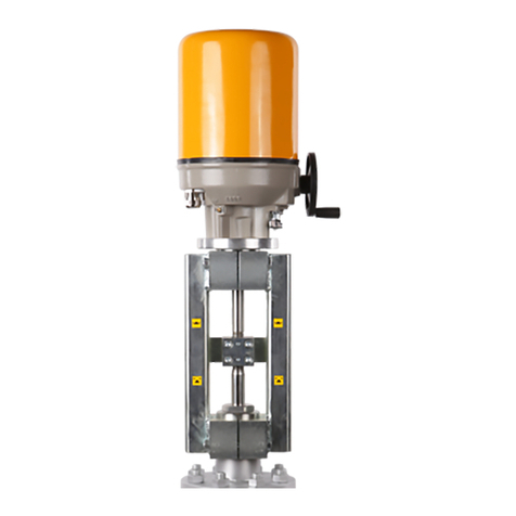
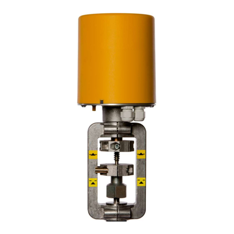
Motorized Rotary Actuator baelz 375-E42
Technical specications subject to change without notice Copyright according to ISO 16016

2 | 32W. Baelz & Sohn GmbH & Co. · Koepffstrasse 5 · 74076 Heilbronn · Germany · www.baelz.de Seite | Page
Motorized Rotary Actuator baelz 375-E42
Table of Contents
1. SAFETY 4
1.1 Intended use 4
1.2 Instructions for the operator 4
1.3 Personnel 5
1.4 Before starting work 5
1.5 During operation 5
1.5.1 Transport, installation and assembly 5
1.5.2 Maintenance and repair 5
1.6 Working environment 5
2. PRODUCT DESCRIPTION 6
2.1 Identication 6
1.7 Motorized rotary actuator 6
2.2 TechnicalSpecications 6
3.2 Accessories and options 7
3.1 Type name 7
2.3 Operating conditions 7
3. TRANSPORT AND STORAGE 7
4. ASSEMBLY 8
4.1 Fitting position 8
4.2 Assembly with the valve 8
4.3 Principle of operation 9
4.3.1 Manual adjustment 9
4.3.2 Removing the cover 9
4.4 Electrical connection 10
4.5 Carrying out the electrical connection 10
5. COMMISSIONING 11
5.1 Setting the mechanical end stops 11
5.2 Setting the limit switches 11
5.3 Test run 11
5.3.1 Checking the direction of rotation 11
5.3.2 Switching off in end positions 12
6. RETROFITTING OF ADDITIONAL COMPONENTS 13
6.1 Retrottingofpotentiometer 13
6.2 Retrottingoftwoadditionaltravelswitches(2EZ) 14
6.3 Fitting the 7020A digital postioner 15

BA_375-E42_01_DEF_MJ_4419
3 | 32W. Baelz & Sohn GmbH & Co. · Koepffstrasse 5 · 74076 Heilbronn · Germany · www.baelz.de Seite | Page
Motorized Rotary Actuator baelz 375-E42
7. DIGITAL POSITIONER 7020A 18
7.1 Intended use 18
7.2 Operational modes and operating options 18
7.2.1 Standard operation using DIP switches 18
7.2.2 Standard operation using Modbus VT100 or direct addressing 18
7.2.3 Modbus mode 18
7.2.4 Normal and safety modes 19
7.2.5 Safety mode: freeze protection and excessive temperature 19
7.2.6 3-point control with a continuous output signal 19
7.3 Wiring diagrams and allocation of connection terminals 19
7.3.1 Wiring diagram 19
7.3.2 Allocation of connection terminals 20
7.4 CongurationoftheDIPswitches 21
7.4.1 Details on DIP switches 22
7.5 Commissioning 24
7.5.1 Quick start guide 24
7.5.2 Initialization run 24
7.5.3 Meaning of LED signals 25
7.6 Errors 26
7.6.1 Errors after an initialization run 26
7.6.2 Errors during normal positioner operation 27
7.7 TechnicalSpecications 28
7.8 Accessories and options 28
8. SPARE PARTS 29
9. DECOMMISIONING AND DISPOSAL 30
10. TROUBLESHOOTING 30
10.1 Checklist for operational malfunctions 31
11. DIMENSIONAL DRAWINGS 32

4 | 32W. Baelz & Sohn GmbH & Co. · Koepffstrasse 5 · 74076 Heilbronn · Germany · www.baelz.de Seite | Page
Motorized Rotary Actuator baelz 375-E42
1. SAFETY
Read these operating instructions, in particular the following safety instructions, carefully
before installation and operation.
Beware
Potentially hazardous situation that could result in minor injury.
Also indicates a hazard that may result in property damage.
Beware
Caution
Potentially harmful situation in which the product or an object in its
vicinity may be damaged.
Caution
Danger
Imminent danger of death or serious injury.
Danger
Warning
Potentially hazardous situation that may result in death or serious injury.
Warning
Application instructions and other useful information.
1.1 Intended use
Baelz 375-E42 motorized rotary actuators are controlled by three-point control or constant
control in combination the digital positioner baelz 7020A. The rotary actuators of the series
described in this document are intended for the rotary adjustment of valves.
Toensuretheirintendeduse,makesurethattheabovetypeidenticationcomplieswiththe
identicationlabeloftherotaryactuatorsbeforestartinganyactivities.Theactualtechnical
dataoftherotaryactuatorsandthepowersupplyrequirementsarethespecicationsindicated
ontheidenticationlabel.
Any use other than the intended use mentioned above, different tasks, and operation with other
power sources than those permitted, is considered to be improper use. In case of improper
use, the operator shall be solely liable for the risk presented to persons and the device as well
as other property!
Intended use also includes compliance with accident prevention and DIN VDE regulations as
well as safe working practices for all measures described in these operating instructions, taking
into account the usual technical regulations.
1.2 Instructions for the operator
Always keep the operating instructions available at the place where the actuator is used!
During installation, operation and maintenance, observe the applicable occupational safety,
accident prevention and DIN VDE regulations. If necessary, observe additional regional, local
or internal safety regulations.
Make sure that every person entrusted with one of the measures described in these operating
instructions has read and understood these instructions.
Tip:

BA_375-E42_01_DEF_MJ_4419
5 | 32W. Baelz & Sohn GmbH & Co. · Koepffstrasse 5 · 74076 Heilbronn · Germany · www.baelz.de Seite | Page
Motorized Rotary Actuator baelz 375-E42
1.3 Personnel
Onlyqualiedpersonnelmayworkonthisrotaryactuatororinitsvicinity.Qualiedpersons
are deemed to be persons who are familiar with the installation, assembly, commissioning and
operationormaintenanceoftheactuatorsandhavetheappropriatequalicationsfortheirjob.
Necessaryorprescribedqualicationsinclude,butarenotlimitedto:
●Training / instruction and the authorization to switch electric circuits and devices /
systemsonandoffinaccordancewithEN60204(DINVDE0100/0113)andthe
technical safety standards
●Training or instruction in the care and use of appropriate safety and work protection
equipment in accordance with safety technology standards.
●First aid training.
Work in a safe manner and avoid any operation that would endanger the safety of persons or
damage the rotary actuator or other property in any way.
1.4 Before starting work
Beforecarryingoutanywork,checkwhetherthetypesspeciedherecorrespondtothe
information on the name plate of the actuator:
baelz 375-E42
1.5 During operation
Safe operation is only possible if transport, storage, assembly, operation and maintenance is
carried out in a safe, proper and professional manner.
1.5.1 Transport, installation and assembly
Observe the general installation and safety regulations for heating, ventilation, air conditioning
and piping systems. Use tools only for their intended purpose. Wear the required personal and
other protective equipment.
1.5.2 Maintenance and repair
Prior to maintenance or repair, make sure that the rotary actuator is disconnected from power
byqualiedpersonnelinaccordancewithDINVDEstandards.Therotaryactuatorrequires
little or no maintenance.
1.6 Working environment
Notetheinformationonworkingenvironmentinthetechnicalspecications.

6 | 32W. Baelz & Sohn GmbH & Co. · Koepffstrasse 5 · 74076 Heilbronn · Germany · www.baelz.de Seite | Page
Motorized Rotary Actuator baelz 375-E42
1.7 Motorized rotary actuator
Thebaelz373-E42isamotorizedrotaryactuatorforowcontrolapplicationsrequiringa90°
rotation,suchasthoseusingdrivebutteryvalvesorballvalves.Theactuatorsaredesigned
for highly accurate positioning in an industrial environment. Manual adjustment can be carried
one-handed and without use of a clutch. The travel-dependent and/or torque-dependent limit
switchescanbeindividuallycongured.
Eachactuatorhasanameplateshowingspecicationsregardingthemaximumoperating
conditionsofthedeviceandaunique,order-relatedserialnumber(Fno.).
Fig. 1: Baelz nameplate for motorized actuators
2. PRODUCT DESCRIPTION
2.1 Identication
2.2 Technical Specications
Table 1. Technical Specifications, baelz 375-E42
Torque Nm 150
Postioning time for 90° s 60(at60Hzthepositioningspeedandpowerconsumptionboth
increaseby20%)
Power consumption (230 V) VA 65
Nominal current (230 V) A 0.28
Type of motor synchronousmotor(syn)
Motor protection thermoswitch
Max. angle of rotation ° 90
Supply voltage 230V50/60Hz±10%(othersupplyvoltagesavailableuponrequest)
Operating mode acc. to IEC 34-1 S3 - 50 % duty cycle 1200 c/h
Cable glands 1 x M20 x 1.5; 2 x blind plug M20 x 1.5
Electrical connection internal terminal block, see wiring diagram for terminal allocation
Limit switches 2 torque dependent and 2 travel dependent switches,
max. 250 V AC, ohmic load: max. 10 A, inductive load: max. 5 A
End positions Mechanical stops, adjustable from the outside
Fitting position as required, but not "head down" with the actuator below the valve
Ambient temperature °C 0 to +50
Position indicator Position indicator in the actuator cover
Manual adjustment crank wheel
IP-rating according to EN 60529 IP 65
Connection type DIN5211,(F04),F05,F07,F10
Weight, approx. kg 7.5

BA_375-E42_01_DEF_MJ_4419
7 | 32W. Baelz & Sohn GmbH & Co. · Koepffstrasse 5 · 74076 Heilbronn · Germany · www.baelz.de Seite | Page
Motorized Rotary Actuator baelz 375-E42
2.3 Operating conditions
In case of extreme variations in ambient temperature and high humidity levels, installation of a
heating resistor is recommended to minimise condensation in the actuator.
Actuatorcoverswithsuppressionofthermalbridges(dualcovers)arerecommended.
● Connecttheheater(HZG)asshowninthewiringdiagram.
●Put the device into service as soon as it is installed.
The actuators are suitable for installation in industrial plants and in waterworks and power
plants with a low pollutant concentration.
Foruseoutdoorsorinanenvironmentwithahighpollutantconcentration,suchasheavytrafc
areas,industrialareas(chemicalplants,sewageplants,etc.),coastalareasandtheopensea,
the actuators must have external parts made of non-corrosive material and must be provided
with a special coating.
When used outdoors, the actuator must be protected with an additional cover against
●rain
●direct sunlight
●strong draughts
●dust
3. TRANSPORT AND STORAGE
Risk of injury caused by failure to observe safety regulations!
Caution
●Wear the required personal and other protective equipment.
● Protecttherotaryactuatorfromimpact,shock,vibrationandsimilarinuences.
● Storetherotaryactuator(orthecompleteactuator/valveassembly)inadryplace.
● Observethetransportandstoragetemperaturelimitsof-20to+60°C.
Table 2. Options for Actuators
2EZ-Fg Two additional limit switches for signalling end positions or intermediate positions, freely adjustable,
max. 250 V AC, rating for resistive load max. 10 A, for inductive load max. 5 A
Fg5k 5kΩpotentiometer,linearityerror≤0.5%,max.1.5W,contactcurrent30mA
7020A
Digital positioner for actuator control, self adapting
1inputsignal:0(2)…10V,0(4)…20mAor(3-point)
2outputsignals:0(2)…10Vand0(4)…20mA
1 digital input, 2 relays for feedback on end or intermediate positions,
InterfaceRS485ModbusRTU,incl.5kΩpotentiometer
Hzg Heatingresistorwiththermoswitchagainstmoisturewithautomatictemperatureregulation,
max. 15 Watts
baelz 375 - E42 - 150Nm - 60s - 230V
motorized rotary actuator actuator type torque positioningtimefor90° supply
3.1 Type name
3.2 Accessories and options

8 | 32W. Baelz & Sohn GmbH & Co. · Koepffstrasse 5 · 74076 Heilbronn · Germany · www.baelz.de Seite | Page
Motorized Rotary Actuator baelz 375-E42
4. ASSEMBLY
Make sure that the specications on the nameplate correspond to those in
the order documents!
4.1 Fitting position
Do not mount rotary actuators "head down" below the valve. Allow for about 200 mm space
above the cover at the site of installation.
4.2 Assembly with the valve
Before assembly, check the rotary actuator for damage. Damaged parts should be replaced
with original spare parts. After assembly, check the rotary actuator for damage to the paint.
Touch up the paint if necessary in order to prevent corrosion.
ForgatevalvestherecommendedassemblypositionistheSHUTendposition.Forthis,
turnthecrankwheelontherotaryactuatorclockwiseuntilthemechanicalstopoftheSHUT
position is reached before assembling.
For ball valves the recommended assembly position is the OPEN end position. For this, turn
the crank wheel on the rotary actuator anticlockwise until the mechanical stop of the OPEN
position is reached before assembling.
Thorouglydegreasethecontactsurfacesoftheconnectingangesoftherotaryactuator
and the valve. Lightly grease the valve shaft. Fit the coupling to the valve shaft and secure it,
keepingtothedimensionsXandY(seeFig. 2 and Table 3,below).
Lubricate gear teeth on the coupling thoroughly with acid-free grease. Fit the actuator so
thattheconnectionholesintheactuatorandthevalveangearealigned,possiblyturning
the actuator on the coupling by one tooth. If necessary, turn the crank wheel slightly towards
OPENorSHUTuntiltheholesarealigned.Ensurecorrectalignment(ifapplicable)and
completecontactofthemountingfaces.Fixactuatorwithscrews(atleastquality8.8)and
spring washers; Tighten screws alternately and gradually up to the torque given in Table 3,
below.
Fig. 2: Coupling / Assembly of actuator and valve
Attention
Table 3. Dimensions for coupling and
tightening torques for screws
Connection X max.
(mm)
Y max.
(mm) size TA
(Nm)
F05 0,5 3 4 x M6 10
F07 0,5 3 4 x M8 25
F10 0,5 3 4 x M10 50
coupling
grub screw
valve
A B
Y
X

BA_375-E42_01_DEF_MJ_4419
9 | 32W. Baelz & Sohn GmbH & Co. · Koepffstrasse 5 · 74076 Heilbronn · Germany · www.baelz.de Seite | Page
Motorized Rotary Actuator baelz 375-E42
4.3 Principle of operation
4.3.1 Manual adjustment
By turning the crank wheel the position of the actuator can be adjusted. This also turns the
motor.
Only carry out manual adjustment when the motor is not in motion. If a positioner is used, the
actuator will automatically move back to the original position. Therefore only carry out manual
adjustment when the actuator is disconnected from the power supply.
It is not necessary to use an extension for a greater mechanical advantage during manual
operation. Use of excessive force can damage the equipment.
4.3.2 Removing the cover
Disconnect the device from the power supply before starting any maintenance or adjustment
work.
●Loosen the four socket-head screws at the corners of the cover
● Gripthecoverandlifttoremove

10 | 32W. Baelz & Sohn GmbH & Co. · Koepffstrasse 5 · 74076 Heilbronn · Germany · www.baelz.de Seite | Page
Motorized Rotary Actuator baelz 375-E42
4.4 Electrical connection
Risk of electric shock!
Danger
Use an appropriate power supply to ensure that no hazardous voltage can enter the
device during normal operation or in the event of a system failure or defective system
components.
Failure to heed this warning may result in death, serious injury or substantial material
damage.
For short-circuit protection and disconnection of the actuator from the power supply, fuses and
switch disconnectors must be provided on site. The current values for the rating depend on the
operatingcurrentofthemotor(refertothenameplate).
Theelectricalconnectionshouldonlybecarriedoutbytrained,qualiedpersonnel.
●Prior to connection, observe the instructions in this chapter.
●After connection, but before applying voltage, observe the instructions in the chapter
"Commissioning"(page11).
●When making the electrical connection, be sure that the power supply is turned OFF!
Ensure protection against unintentional reconnection to the power supply!
●For wiring and connection, observe the regulations for the construction of electric power
installations and the regulations of the local energy supplier!
● Checkcomplianceofthesupplyvoltageandfrequencywiththespecicationsonthe
nameplate of the actuator and on the nameplate of the actuator motor.
●Always select the cable cross section so as to match the actuator's power consumption
and the required cable length. Minimum cross section of the cable for this rotary
actuator: 1-2.5 mm²
In case of malfunction:
Dangerous voltage if protective earth conductor is NOT connected! Risk of electric shock!
→Donotoperatethedeviceiftheprotectiveearthconductorisnotconnected!
Trapped wires can lead to short circuiting! Risk of electric shock and malfunction.
4.5 Carrying out the electrical connection
Risk of electric shock!
Danger
→Disconnectthedevicefromthepowersupplybeforeremovingcover.
Always use the wiring diagram on the inside of the cover or supplied with the actuator.
Replace the dummy plugs with cable glands.
1. Strip the cable as necessary.
2. Strip the ends of the individual wires.
3. Forexiblewires:UsewireendferrulesasspeciedinDIN46228.
4. Connectthewiresasshowninthejob-specicwiringdiagram.
The IP-rating shown on the nameplate is only valid if suitable cable glands are used.

BA_375-E42_01_DEF_MJ_4419
11 | 32W. Baelz & Sohn GmbH & Co. · Koepffstrasse 5 · 74076 Heilbronn · Germany · www.baelz.de Seite | Page
Motorized Rotary Actuator baelz 375-E42
5. COMMISSIONING
Comparetheactuatortorqueandthesettravelwiththetechnicalspecicationsofthevalve.
Overloading can lead to serious damage to the valve. Watch out for moving parts during
assembly and adjustment. Risk of injury and substantial material damage.
The rotary actuator is factory set to a rotational travel of 90°.
Actuators with positioners are supplied with a control input signal of 0-10
unless otherwise stipulated upon ordering.
Caution
5.1 Setting the mechanical end stops
Move the actuator out of the end position, tighten
the stop screw to the dimension shown in Fig. 3 and
counter-tighten the nut. The stop screw should not
beturnedoutofthespeciedrange.Iftherangeis
exceeded, rotate the coupling by one tooth relative to
the output shaft. Fig. 3: Setting the mechanical end
stops
5.2 Setting the limit switches
Move actuator into chosen end position. Open the
eccentrictappet(1)usinga10mmwrenchand
adjusttheswitchcamwithascrewdriver(7).Close
theeccentrictappetagainusingthewrench(Fig. 4).
Use of the limit switches to switch off the actuator
will prolong its lifespan.
Fig. 4: Setting the limit switches
5.3 Test run
5.3.1 Checking the direction of rotation
●Adjust the actuator manually to roughly the middle position.
●In direction of travel CLOSE, switch the actuator on and watch the direction of rotation.
●If the direction of rotation is wrong, switch off immediately.
● Checkwiring(jumpers).
●Repeat the test run.
~19mmfor90°
(Min:12,9/Max:25,1)±15°
F05
F07
F10
EZ2
EZ1
WER
WEL
unlock
lock
1
6
2
3
4
5
7
If the direction of travel is set incorrectly, damage to actuator and valve is
imminent as the limit switches will not function with the wrong direction of
rotation!
Attention

12 | 32W. Baelz & Sohn GmbH & Co. · Koepffstrasse 5 · 74076 Heilbronn · Germany · www.baelz.de Seite | Page
Motorized Rotary Actuator baelz 375-E42
5.3.2 Switching off in end positions
Risk of electric shock!
Danger
If the switches in the actuator are not factory-wired, check proper switching off in end positions:
With the cover removed, the rotary actuator may only be operated briey for test runs or
when performing absolutely essential adjustments on electrical components, such as
potentiometer, limit switches or positioning electronics.
While performing this activity, there is unobstructed access to hazardous, live, exposed,
moving and rotating parts. Adjustments performed incorrectly or without exercising the
necessary caution may result in death, serious injury or substantial material damage.
Any operation of the rotary actuator with the cover removed for a purpose other than
that described above is prohibited.
Use an insulated screwdriver to actuate the switching rollers of the DE switches as shown in
the wiring diagram, Fig. 9, page 19, and check that the each switch actually switches off the
motor. If necessary, change the motor supply jumpers.

BA_375-E42_01_DEF_MJ_4419
13 | 32W. Baelz & Sohn GmbH & Co. · Koepffstrasse 5 · 74076 Heilbronn · Germany · www.baelz.de Seite | Page
1
10
2345
6
7
3
8
9
5
1
8
9
7
Motorized Rotary Actuator baelz 375-E42
6. RETROFITTING OF ADDITIONAL COMPONENTS
6.1 Retrotting of potentiometer
Disconnect actuator from power supply before starting work!
Danger
1. Remove capacitor bracket.
2. If the actuator is equipped with a heating element, the potentiometer retaining plate [5]
isalreadyttedandcanbeusedforpotentiometerassembly.PutpotentiometerR1[1]
into retaining plate [5] and fasten with a lock washer and nut. Place two locking rings
onthepinion[8]andtthepiniontothepotentiometershaft.Solderthepotentiometer
wiring to the potentiometer, insert downwards through the Ø8 mm hole and connect to
the lower part of the plug connector [2] red-28, gray-29, yellow-30. Fix the lower part of
the plug connector [2] to the potentiometer retaining plate [5] using allen screws M2.5x6
[4].
3. Ifnoheatingelementistted,clipthespacer[9]tothepotentiometerretainingplate
[5]. Replace the allen screw on the gear cover with the spacer bolt M4x22 [7]. Fit the
potentiometer retaining plate [5] into the actuator, clip the spacer [9] into the gear cover
andxtospacerboltM4x22[7]usingallenscrewM4x6.Toeliminatebacklash,gently
push the potentiometer assembly in the direction of the camshaft whilst tightening the
screw.Insertthecapacitorbracketintotheretainingplate[5]andxwithallenscrew
M4x6.
Fig. 5: Fitting the potentiometer
2 x locking ring

14 | 32W. Baelz & Sohn GmbH & Co. · Koepffstrasse 5 · 74076 Heilbronn · Germany · www.baelz.de Seite | Page
12
3
4
31
4
1
2
1
3
Motorized Rotary Actuator baelz 375-E42
6.2 Retrotting of two additional travel switches (2EZ)
Disconnect actuator from power supply before starting work!
Danger
1. Remove the two allen screws [1] on the main switch board. Replace them with two
spacer bolts [3].
2. Clip the spacer [2] into the main switch board.
3. Cliptheadditionalswitchboard[4]ontothespacer[2]andxwiththeallenscrews[1].
4. Adjust the cams according to the instructions in section 5.2
Fig. 6: Retrotting of two additional travel switches (2EZ)

BA_375-E42_01_DEF_MJ_4419
15 | 32W. Baelz & Sohn GmbH & Co. · Koepffstrasse 5 · 74076 Heilbronn · Germany · www.baelz.de Seite | Page
Motorized Rotary Actuator baelz 375-E42
6.3 Fitting the 7020A digital postioner
Disconnect actuator from power supply before starting work!
Danger
1. Remove the two screws indicated below.
2. Replace the screws with the spacer bolts
3. Placetheadaptorpanelontothespacerboltsandthecapacitorbracketandxwith
the metal countersunk screws. IMPORTANT NOTE: The holes in the adaptor panel are
notsymmetrical;theoutermostholeisatthetopleft(seeright-handphotobelow).The
bottom right-hand hole remains unused.
spacer bolt
M4 x 38 mm
washer 1.6mm
(onlywithout
additional travel
switches)
spacer bolt
M4 x 22 mm
(onlywithout
additional travel
switches)
spacer bolt
M4 x 85 mm

16 | 32W. Baelz & Sohn GmbH & Co. · Koepffstrasse 5 · 74076 Heilbronn · Germany · www.baelz.de Seite | Page
Motorized Rotary Actuator baelz 375-E42
1. Fix the isolation panel with the 4 plastic countersunk screws. Tighten gently, so as not
to damage the screw thread.
2. Fit the 7020A digital positioner circuit board. To do this, place the plastic spacer sleeves
over the four threaded holes in the corners of the isolation panel. Insert the slotted
cheese-headscrews(M3)intotheholesinthecircuitboard,thenplacethecircuitboard
onto the isolation panel. Tighten all four screws. Make sure that the spacer sleeves
remain between the isolation panel and the circuit board.

BA_375-E42_01_DEF_MJ_4419
17 | 32W. Baelz & Sohn GmbH & Co. · Koepffstrasse 5 · 74076 Heilbronn · Germany · www.baelz.de Seite | Page
Motorized Rotary Actuator baelz 375-E42
3. Wire up the circuit board and the actuator using the wiring provided and according to
the wiring diagram provided.
4. Afterttingthedigitalpositioner,stickthewiringdiagramontotheinsideoftheactuator
cover as shown.

18 | 32W. Baelz & Sohn GmbH & Co. · Koepffstrasse 5 · 74076 Heilbronn · Germany · www.baelz.de Seite | Page
Motorized Rotary Actuator baelz 375-E42
7. DIGITAL POSITIONER 7020A
7.1 Intended use
The digital positioner baelz 7020A controls the actuator according to the value of the control
signal:0(2)-10V,0(4)-20mA
Toensureuseforthepurposeintended,checkthattheabovetypeidenticationcorresponds
tothenameplateonthepositionerbeforestartinganyactivities.Thetechnicalspecicationsof
the positioner and the power supply requirements are the indicated on the name plate.
Any use other than the intended use stated above, use for different tasks, and operation
with other power sources than those permitted, is considered to be improper use. In case of
improper use, the operator shall be solely liable for the risk presented to persons and to the
device as well as to other property!
The intended use also comprises compliance with the accident prevention regulations and
theDINVDEstandardsoftheGermanInstituteforStandardizationandtheAssociationfor
Electrical, Electronic & Information Technologies. It also implies working in accordance with the
safety requirements when performing all activities described in these operating instructions,
under consideration of general technical rules and regulations.
7.2 Operational modes and operating options
For further information and additional functions, see baelz 7020 operating instructions.
7.2.1 Standard operation using DIP switches
TheDIPswitchescanbeusedtocarryoutstandardcongurationsandoperations(see
section 7.4).
When DIP switch 11 is set to 0, the 7020A is in the standard operational mode.
In standard mode, all DIP switches are active and the functions of the Baelz 7020A can be
individuallyadapted.Functionswhicharepredenedandunalterableinstandardmodeare
described in section 6.1 of the baelz 7020 operating instructions.
7.2.2 Standard operation using Modbus VT100 or direct addressing
In standard mode, the Baelz 7020A can be operated using Modbus VT100. For this, a virtual
7020A display and a virtual 7020A keypad are transmitted to a user interface. Modbus direct
addressing, e.g. from a building automation system, enables access to status information and
allowsoperationandconguration.(Seebaelz7020operatinginstructions,AppendixA).The
settings given by the DIP switches remain active. Values which are only relevant in Modbus
mode can be adjusted in standard mode, but only take effect in Modbus mode.
7.2.3 Modbus mode
When DIP switch 11 is set to 1, the Baelz 7020A is in Modbus mode. In Modbus mode, the
7020AisatitsmostexibleandcanbeconguredandoperatedusingeitheraModbusVT100
or Modbus direct addressing, for example in a building automation system. See separate
operating instructions "Baelz 7020 Digital Positioner - Operating Instructions for Modbus mode"
Tip:

BA_375-E42_01_DEF_MJ_4419
19 | 32W. Baelz & Sohn GmbH & Co. · Koepffstrasse 5 · 74076 Heilbronn · Germany · www.baelz.de Seite | Page
Motorized Rotary Actuator baelz 375-E42
7.2.4 Normal and safety modes
In normal mode the position of the valve is controlled by the set
valueatanalogueinputAI2.TheN↔Sswitchshowninthepicture
ontherightissettonormalmode(N).Innormalmode,noexternal
control systems can be connected to terminals 12 and 14.
7.2.5 Safety mode: freeze protection and excessive temperature
Insafetymodetheactuatorcanbesenttoasafeposition(extended/retracted,dependingon
thedirectionofactionofthevalve)incaseoffailureormalfunctioningofthemicrocontroller.
To operate the Baelz 7020 in connection with an external freeze protection and/or excessive
temperaturethermostat,settheN↔Sswitchtosafetymode(S).
Connect the freeze protection and/or excessive temperature thermostat according to desired
function and priority. Be sure to take the direction of action into account! See wiring diagrams
in the baelz 7020 operating instructions.
7.2.6 3-point control with a continuous output signal
1. Set the positioner up and wire to power supply as described
previously and initialize as described in section 7.5.2.
2. To deactivate the error signal, if desired, set the DIP-switch 11 to 1
("ON")andchangethefollowingvaluesinthemenuitem"CA"using
WinBasTools(onPC,seebaelz7020operatinginstructions):
●AD to 0
●EFP to 0.0%
●LA to 1
(Ifyoudon'tmindtheredLEDerrorsignal,step2canbeleftout
completely.Thishasnoeffectonthefunctionofthepositioner.)
3. SettheN↔Sswitch(Fig. 7)to"S"andwireasshowninFig. 8(thepositionermust
remainconnectedtothepowersupplythroughout).
4. The required signal can now be picked up on AO1 and AO2.
IMPORTANT NOTE: Before any further re-initialization of the device, disconnect terminals 12
and14andsettheN↔Sswitchtonormaloperation(N).
7.3 Wiring diagrams and allocation of connection terminals
Disconnect actuator from power supply before starting work
See also section 4.4.
Danger
7.3.1 Wiring diagram
Fig. 7: N↔S-switch
Fig. 8: Wiring diagram
3-point-signal
Fig. 9: Wiring diagram
basic actuator

20 | 32W. Baelz & Sohn GmbH & Co. · Koepffstrasse 5 · 74076 Heilbronn · Germany · www.baelz.de Seite | Page
Motorized Rotary Actuator baelz 375-E42
Fig. 10: Wiring diagram with digital positioner baelz 7020A
7.3.2 Allocation of connection terminals
Terminal Allocation Notes
2, 3 supply terminals See wiring diagram for
correct allocation.
4, 5, 12, 14 Can be allocated to an
overriding external control
system(freezeprotection,
excessivetemperatures).
For external control, the
N↔Sswitchmustbeset
to„S“(safetymode).
20, 22 Digital input for a switch
used to select between two
conditions,
e.g. „open / closed“ or
„summer / winter“.
23, 24, 25,
26
Analogue output position
indicater using voltage and
/ or current.
Analogue outputs
can be connected
simultaneously.
38, 39, 40 Connection terminals for
Modbus
91, 92, 93 Connection terminals for
potentiometer
U, 0, I Input setpoint value for
valve position
IMPORTANT! Position of
DIP switch 1, see section
7.4
E1, E2, E3,
E4, E5, E6
Terminals for 2 digital
outputs
IMPORTANT! Position of
DIP switches 5 & 6, see
section 7.4
97, 98, 99 Connection terminals for
motor
Ex-works wiring varies
according to type of
actuator
This manual suits for next models
1
Table of contents
Other Baelz Automatic Controllers manuals