Baer UniMod GSM-3 User manual

E122001606063
UniMod GSM-3
Operation Manual
Bär Industrie-Elektronik GmbH
Rathsbergstraße 23
D-90411 Nürnberg
Germany
Phone +49 911 970590
Fax +49 911 9705950
Internet: www.baer-gmbh.com

Page 2 of 12 UniMod GSM-3
Operation Manual
Bär Industrie-Elektronik GmbH ⋅Rathsbergstr. 23 ⋅D-90411 Nürnberg ⋅Phone +49 911 970590 ⋅Fax +49 911 9705950
Contents
Page
1. Requirements.................................................................................................. 3
2. Safety Precautions for the User..................................................................... 3
3. Power Supply Unit.......................................................................................... 3
4. Interfaces......................................................................................................... 4
5. Display............................................................................................................. 4
6. Installation Hints............................................................................................. 4
7. Programming the Modem............................................................................... 5
8. Additional Functions...................................................................................... 9
9. Signal Quality.................................................................................................. 9
10. SMS................................................................................................................ 10
11. Technical Data .............................................................................................. 11
12. Inserting the Interface Modules................................................................... 12
13. Terminal Block.............................................................................................. 12

UniMod GSM-3
Operation Manual Page 3 of 12
Bär Industrie-Elektronik GmbH ⋅Rathsbergstr. 23 ⋅D-90411 Nürnberg ⋅Phone +49 911 970590 ⋅Fax +49 911 9705950
UniMod GSM-3
The world-wide GSM radio networks (GSM = Global System for Mobile communication) provide be-
sides digital voice communication the possibility to transmit data. In that operation mode is it possible
to send fax, data (CSD: Circuit Switched Data connection), GPRS: General Packet Radio Service) and
short messages (SMS). The universal radio modem UniMod GSM-3 is supposed for remote inquiry of
measurement data of any kind, especially however for telecounting applications.
1. Requirements
The UniMod GSM-3 can be used in any GSM 900/1800 MHz network with an arbitrary number of pro-
viders. It requires however the infrastructure for operating mobile stations with 2 Watt (EGSM900) or
1 Watt (GSM1800) transmission power. The modem supports an interface for 3V SIM cards. For
communication a SIM card with call number for 9600 Baud transmission is needed.
For the UniMod GSM-3 communication modules produced by internationally renowned companies are
used. These companies update their software packages regularly and add or change features. The
software releases are continuously checked by the development department, but no responsibility for
this software releases can be take over except of warranty granted by the module producer.
2. Safety Precautions for the User
Aircraft safety
Cellular engines can interfere with an aircraft’s navigation system and its cellular network. The use of
UniMod GSM-3 on board aircraft is forbidden by law. Failure to comply with this prohibition may lead
to temporary suspension or permanent cancellation of cellular engine services for the person who
infringes this prohibition and/or to legal action against said person.
Environments with explosive substances
a) Users are advised not to use the device in automotive service stations.
b) Users are reminded of the necessity to comply with restrictions regarding the use of radio devices in
fuel depots, chemicals plants and locations where explosives are ignited.
Non-ionising radiation
As is the case with other mobile radio transmitters, operating personnel are advised to use the device
in the normal operating position only in order to ensure optimum performance and safety. Avoid touch-
ing the antenna.
Personnel
Installation and repairing should be done by experienced personnel only.
Connecting to other devices
In order to connect the UniMod GSM-3 to another device please read the device’s operation manual to
obtain detailed information about safety. Don’t connect devices, which are not approved by manufac-
turer.
Precautions in the event of loss/theft of the Cellular Engine and the SIM card
If your UniMod GSM-3, your SIM card or both go missing, notify your network operator immediately in
order to avoid misuse.
3. Power Supply Unit
The modem is equipped with a built-in, low-loss switched power supply, which enables it to operate
on a wide-range AC or DC supply voltage.
•AC: 80 V - 270 V or DC: 60 V - 375 V
Attention: NEVER remove the interface modules or the SIM card when the device is pow-
ered! The card and especially it’s contact pads can be damaged very easily by
scratches or bending. Be careful when inserting or removing it.

Page 4 of 12 UniMod GSM-3
Operation Manual
Bär Industrie-Elektronik GmbH ⋅Rathsbergstr. 23 ⋅D-90411 Nürnberg ⋅Phone +49 911 970590 ⋅Fax +49 911 9705950
4. Interfaces
Communication is possible with many standard protocols, like SCTM, LSV1, DLMS, IEC1107,
IEC60870 (transparent reading) etc. The interface for connecting the target device can be specified by
plugging the appropriate interface module. The following module types are available now:
•CS (20 mA current loop) interface module, active (supplies current for 4 devices max.) or passive
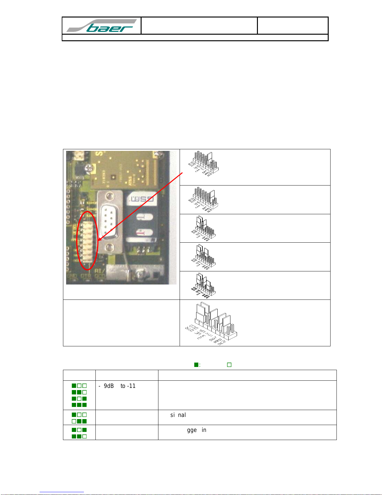
•RS232 interface module (uses signals RxD, TxD, CTS, RTS, GND, DTR, DCD/DSR)
•RS485 interface module
•M-Bus interface module, active (can supply 10 devices max.) or passive
5. Display
The followingLEDs display the current operating status of the modem and giveinformation about the data
transfer
•Power-LED signals, that the modem is supplied with power.
•GSM-LED permanently off: power down mode
600 ms on / 600 ms off: Limited Network Service: No SIM card inserted
or no PIN entered, or network search in progress, or ongoing user authentication,
or network login in progress
75 ms on / 3 s off: IDLE mode: The mobile is logged to the network (monitoring
control channels and user interactions). No call in progress
permanently on: CSD call: Connection to remote party
•INF-LED’s lights (information): 3 LED’s
first LED on: Modem is ready for operation (15 to 30 sec. after Power On)
•RI-LED lights, when the modem rings
•DCD-LED lights, when the modem has built a data link to remote station
•TxD-LED lights, when data is transferred from modem to target device (e.g. meter)
•RxD-LED lights, when data is transferred from target device to modem
6. Installation Hints
The installation must be done in a way, that even in the case of cable break no dangerous voltages
are applied to touchable parts of the device including the antenna. This can be accomplished e.g. by
using cable ties and appropriate shortening of the cables.
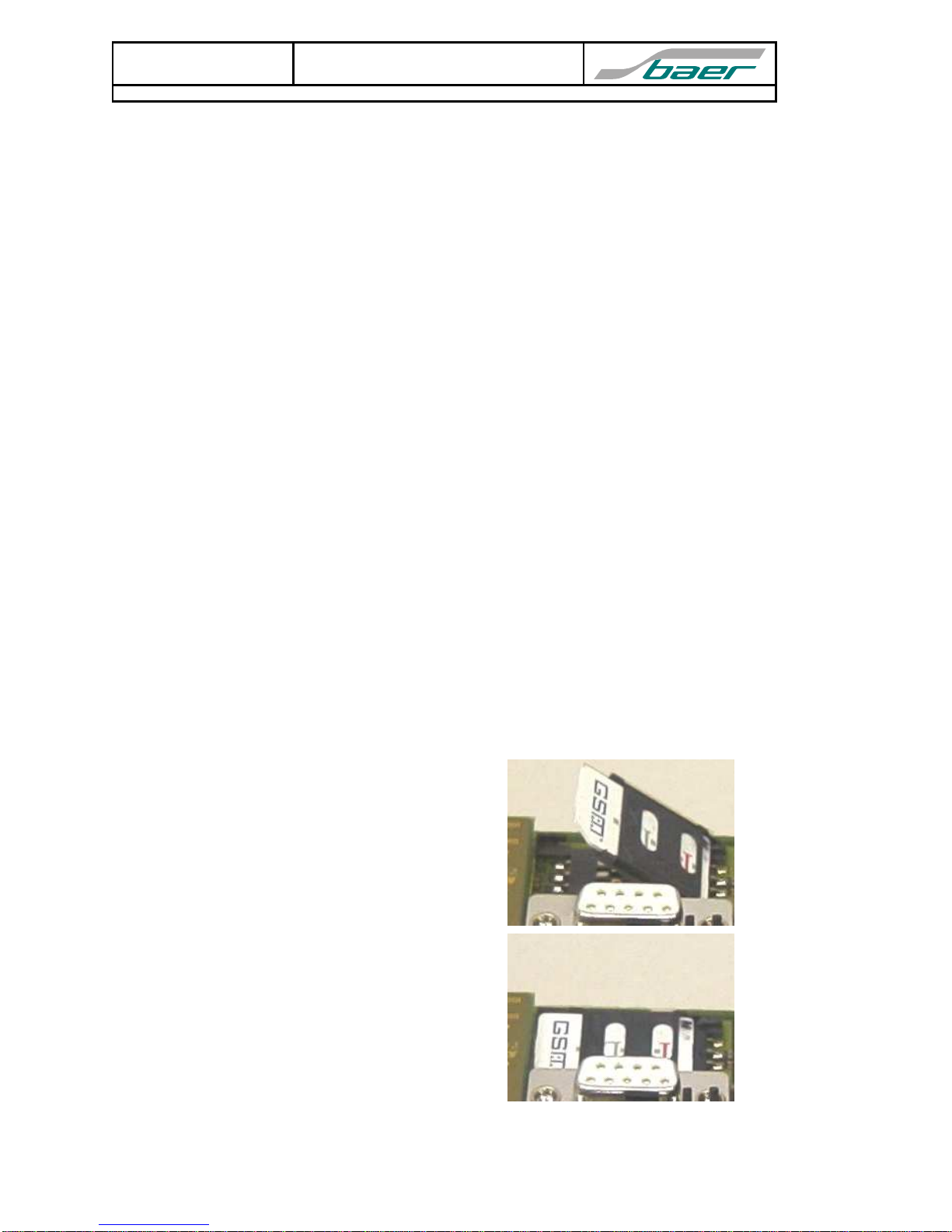
For installation insert the SIM card correctly and tighten it by using the clamp of the card reader:
1. First open the clamp by shifting the slide in
the arrow’s direction (OPEN). After release
you can open the lid and insert the SIM card
as shown in the picture. Please note the posi-
tion of the bevelled edge: it must point at the
lower-right side. The golden contact pads
have to point downwards.
2. Insert the card until the lid can be closed as
shown in the picture. The slide must be mov-
able in this position. Please note the position
of the bevelled edge. Now move the slide
against the arrow’s direction until it clicks into
place and the lid is locked. The SIM card is
now ready to use.
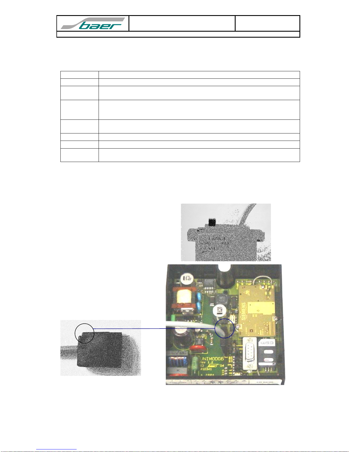
3. After that connect the antenna to the UniMod GSM-3 using the FME plug. At last (important!) con-
nect it to the supplying power.

UniMod GSM-3
Operation Manual Page 5 of 12
Bär Industrie-Elektronik GmbH ⋅Rathsbergstr. 23 ⋅D-90411 Nürnberg ⋅Phone +49 911 970590 ⋅Fax +49 911 9705950
7. Programming the Modem
Before installing the modem it has to be programmed in order to meet the demands. The baud rate
and data format for connecting the target device and the transmission mode and transmission rates
must be adjusted. On delivery the following default parameters are active:
Data rate 9600 Bit/sec (if not differently mentioned)
Data format 7, Even, 1 (if not differently mentioned)
S0=1 This parameter setting determines the number of rings (here 1) before automatic
answering.
&D0 This parameter determines how the modem responds when circuit 108/2 (DTR) is
changed from ON to OFF during data mode. With setting 0 the modem ignores
DTR.
E0 This setting determines whether or not the modem echoes characters received
from PC during command state. (0 = no echo)
Q0 V0 Information response: numeric code
+IPR=19200 Internal baud rate: don’t change this value!
+CBST=7,0,1 The modem selects the bearer service with data rate 9600 Baud, asynchronous,
non-transparent mode to be used when data calls are originated.
This configuration allows for reading standard counters according to VDEW2 (IEC 1107, EN 62056-
21). If you want to change this parameters, you need a PC with terminal software (e.g. Windows
HyperTerminal, Telix etc.). Moreover experiences with the Hayes AT modem command set are very
recommended. To establish connection between PC and modem you have to use a converter („con-
verter box“) in order to adapt the interfaces. Alternatively you can use a parametering adapter, which
can be plugged instead of an interface module. This adapter can be ordered as accessory.
1. First set the switch to position
"←GSM", as shown in the picture.
Then connect the 25 pole plug
(RS232) to the PC.
2. Disconnect the modem from the
supply (important!) and remove the
interface module.
3. Insert the 7 pole plug of the pa-
rametering adapter instead of the
interface module. The notch must
point in direction of the SIM card
reader.
4. After programming switch off the UniMod and insert the interface module carefully again.

Page 6 of 12 UniMod GSM-3
Operation Manual
Bär Industrie-Elektronik GmbH ⋅Rathsbergstr. 23 ⋅D-90411 Nürnberg ⋅Phone +49 911 970590 ⋅Fax +49 911 9705950
Alternative: parametering adapter with
9 pole plug (standard RS232).
Now you have to set your terminal program to the fixed, local data rate and data format of the UniMod.
(Default values: 9600 Bit/sec, 7,E,1) Use one of the AT commands (e.g. ATS0?, ATI, AT&V) in order
to check whether the modem answers. If you see the answer on the screen, the interface is working
correctly.
Note: Simply typing „AT“ does not result in an answer, because the modem is by default programmed
not to send messages and echoes (Parameters ATQ1 and ATE0).
Following some examples of AT commands (the answers depend upon the respective firmware ver-
sion):
Request Answer Description
AT&V ACTIVE PROFILE:
E0 Q0 V1 X4 &C1 &D2 &S0 \Q3
S0:001 S3:013 S4:010 S5:008
S6:000 S7:060 S8:000 S10:002
S18:000
+CBST: 7,0,1
+CRLP: 61,61,78,6
+CR: 0
+FCLASS: 0
+CRC: 0
+CMGF: 1
+CSDH: 0
+CNMI: 0,0,0,0,1
+ILRR: 0
+IPR: 19200
+CMEE: 0
^SMGO: 0,0
+CSMS: 0,1,1,1
^SACM: 0,"000000","000000"
^SCKS: 0,1
+CREG: 0,1
+CLIP: 0,2
+CAOC: 0
+COPS: 0,0,"E-Plus"
+CGSMS: 3
Inquires current configuration
ATI SIEMENS
TC45
REVISION x.xx
Requests product information

UniMod GSM-3
Operation Manual Page 7 of 12
Bär Industrie-Elektronik GmbH ⋅Rathsbergstr. 23 ⋅D-90411 Nürnberg ⋅Phone +49 911 970590 ⋅Fax +49 911 9705950
AT+CPIN? code
OK SIM card inquiry
(code = ERROR: no/faulty SIM card
code = +CPIN: SIM PIN: waiting for PIN
code = +CPIN: READY: PIN active)
AT+CPIN="n"
OK Enter PIN, switches modem active.
e.g. AT+CPIN="1234" (if PIN is 1234)
AT+CLCK=
"SC",0,"n" OK Disable PIN lock after power off. (n = PIN)
e.g. AT+CLCK="SC",0,"1234"
Attention: First enter PIN using AT+CPIN.
AT+COPS? +COPS: 0,0,"Bearer"
OK Inquire bearer service. Will be shown only,
when SIM card is active and antenna con-
nected.
AT+COPS=?
+COPS:
(2,"E-Plus",,"26203"),
(3,"Vodafone.de",,"26202"),
(3,"o2 - DE",,"26207"),
(3,"T-Mobile D",,"26201"),,(0-4),(0,2)
List of available bearer services.
AT+CBST=s,
n,e OK Choose transmission mode
(speed s=1 for 300 Bit/sec V.21, s=2 for
1200 V.22, s=3 for 1200/75 V.23, s=4 for
2400 V.22bis, s=5 for 2400 V.26ter, s=6 for
4800 V.32, s=7 for 9600 V.32, s=65 for 300
V.110, s=66 for 1200 V.110, s=68 for 2400
V.110, s=70 for 4800 V.110, s=71 for 9600
V.110),
(name n=0 for asynchronous mode),
(element e=0 for transparent oder e=1 for
non transparent transmission)
e.g.. at+cbst=7,0,1 (for 9600 Bit/sec V.32,
asynchronous mode, non transparent)
AT&F OK Set all parameters to factory defaults.
Attention: Data rate and data format will
be changed to 19200 Bit/sec, 8, N, 1. Ad-
just parameters of terminal program re-
spectively.
ATS0=n OK This parameter setting determines the num-
ber of rings (0 to 255) before automatic an-
swering.
e.g. ATS0=1 (Modem answers after first
ring)
Attention: ATS0=0 disables automatic
answering.
ATS0? 1
OK Returns the number of rings before auto-
matic answering.
ATE0 OK This disables the modem to send echoes of
characters received from PC during com-
mand state.
ATQ1 (no answer) This parameter setting disables transmission
of result codes to the PC. Information text
transmitted in response is not affected by
this setting.
AT&W (no answer because of ATQ1) Saves the current parameter setting in the
user-defined profile. This settings are active
after every resumption of power supply.
Attention: At the end of every programming the settings have to be saved permanently using
the AT&W command. This ensures that the parameters are restored after power
failure.

Page 8 of 12 UniMod GSM-3
Operation Manual
Bär Industrie-Elektronik GmbH ⋅Rathsbergstr. 23 ⋅D-90411 Nürnberg ⋅Phone +49 911 970590 ⋅Fax +49 911 9705950
Example:
•Establish connection PC to modem (e.g. using the parametering adapter)
•Insert SIM card
•Switch on UniMod GSM-3, wait 15 to 30 sec: till first LED is on
•Start the UniModSet software
•Read the equipment configuration
•Adjust the parameter
•Write the configuration
•Check the signal quality: possible only by CSD-Mode
Testing the connection
For easier diagnosis of connection problems it is possible to display extended result codes for incom-
ing call indication. In order to do this the following steps are necessary:
•Activate result codes: Enter „ATQ0“, Modem reply: OK.
•Activate extended result codes: „AT+CRC=1“, Modem reply: OK. („AT+CRC=0“ switches the ex-
tended codes off)
•Call UniMod GSM-3 via data service (use appropriate telephone number). Watch incoming call
using terminal program. Possible messages:
+CRING: REL ASYNC incoming call has been correctly transmitted. That’s OK.
+CRING: VOICE incoming call has been transmitted via „voice“ mode.
Call rejected by modem.
+CRING: FAX incoming call has been transmitted via „fax“ mode.
Call rejected by modem.

UniMod GSM-3
Operation Manual Page 9 of 12
Bär Industrie-Elektronik GmbH ⋅Rathsbergstr. 23 ⋅D-90411 Nürnberg ⋅Phone +49 911 970590 ⋅Fax +49 911 9705950
Unusual reaction using "7" data bits and "Even Parity" during data retrieval.
Depending on certain circumstances (software configuration, hardware configuration of the PC, con-
nection of the modem to the PC, operating system,...) the communication software of your application
might issue a message like: wrong parity. In the most cases a switch of the UniMod GSM-3 data for-
mat from "7E1" to "8N1" is able to bring fast and easy help. Using this configuration data retrieval from
most meters is possible in the format "7E1" and "8N1". If there are any further questions we are happy
to help you.
8. Additional Functions
Optional it is possible to activate the time-controlled modem-reset. With this turned on the modem is
regularly deactivated by the internal firmware. After the reset it logs on to the PLMN (Public Land Mo-
bile Network) again. Activating is recommended when the field-strength of the used GSM-net is very
low.
The functionality is activated by the switches below the LEDs.
Internal programming by AT com-
mands: the internal CPU can option-
ally send the AT commands to the
TC45 module
Allow programming
DCD-Signal follows V.24-Standard
DCD-Signal inverted
Parametering with SIM-Card-Out
Standard:
Delivery condition
9. Signal Quality
Check the signal quality and show it by INF-LED(
:LED on /
: LED off):
INF-LED Signal level Description
-99dBm to -113dBm
-83dBm to -97dBm
-67dBm to -81dBm
-51dBm to -65dBm
Bad signal quality;
Low signal quality;
Medium signal quality;
Good signal quality;
undefined No signal quality;
undefined Modem logged in GPRS-Network;
Note: During the connection and 60 seconds after it is the signaling disabled!

Page 10 of 12 UniMod GSM-3
Operation Manual
Bär Industrie-Elektronik GmbH ⋅Rathsbergstr. 23 ⋅D-90411 Nürnberg ⋅Phone +49 911 970590 ⋅Fax +49 911 9705950
10.SMS
Optional it is possible to activate SMS. This function is monitoring of on/off state changes of DTR input
(terminal 8 and 9):
Standard RS232: Function DCD/DTR SMS: Function UA/UE
Example: 20mA interface with two meters and SMS input (contact):
1 1098765432
UniMod GSM-3
Interface: 20mA
Baudrate: 9600 7e1
GSM
85 - 265 VAC
60 - 375 VDC
SMS
20mA
GSM 900 / 1800
(GPRS)
XXXXXXX XXXXXXX
Maximum: one SMS per 10 seconds.

UniMod GSM-3
Operation Manual Page 11 of 12
Bär Industrie-Elektronik GmbH ⋅Rathsbergstr. 23 ⋅D-90411 Nürnberg ⋅Phone +49 911 970590 ⋅Fax +49 911 9705950
11.Technical Data
Housing: Wall-mounted housing
Degree of protection: IP52 (IEC)
Dimensions: W = 105 mm,
H = 179 mm
D = 72 mm
Protection class: 2
Supply voltage: AC: 80 V – 270 V
DC: 60 V – 375 V
Power consumption: 4 VA max. (depends upon supply voltage, kind of interface module
and operating status of transmission unit)
Interfaces: Pluggable modules; available are:
- RS232 (supports signals RxD, TxD, RTS, CTS, GND, DTR,
DCD/DSR)
- CS (20 mA current loop) active (can supply 4 meter max.) or pas-
sive
- RS485 2- or 4-wires
- M-Bus active (can supply 10 devices max.)
Parametering interface RS232 (RxD, TxD, GND, DTR, DCD), RTS and CTS bridged
SMS input 3VDC
Display: LED’s: Power, GSM, 3 INF, RI, DCD, TxD, RxD
GSM unit: Cellular Engine Siemens TC45 with 3V SIM-Card interface
GSM band: Dual band EGSM900 and GSM1800 (GSM Phase 2/2+)
GPRS: Multi-slot class 8: downlink 4 timeslots, uplink 1 timeslot
Transmission rate remote
modem to UniMod: 9600 bit/sec (V.32 / V.110), 7 / 8 data bits, asynchronous
Transmission rate UniMod
to connected device: 300 to 19200 bit/sec (fixed baud rate)
optionally: mode B and C according IEC1107 (EN 62056-21)
Transmission mode: 7E1, 8N1, 8E1, ...
Output power: 2W (Class 4) for EGS900 MHz
1W (Class 1) for GSM1800 MHz
Sensitivity: -104 dBm (demand for normal mobile station)
Antenna jack 50ΩFME
Software-Interface: Hayes Standard-AT, GSM 07.07, GSM 07.05
References: European Telecommunications Standards Institute,
http://www.etsi.org
License: EU-License: Reg.-No.: M351277P-EO
Extent of delivery: - UniMod GSM-3 including interface module as ordered
- Standard antenna (length of cable about 2,6m)
- Operation manual
Accessories: - Adapter for parametering
- Antenna for special purposes
- Additional interface modules
- Software UniModSet

Page 12 of 12 UniMod GSM-3
Operation Manual
Bär Industrie-Elektronik GmbH ⋅Rathsbergstr. 23 ⋅D-90411 Nürnberg ⋅Phone +49 911 970590 ⋅Fax +49 911 9705950
12.Inserting the Interface Modules
When inserting the interface modules their component side must be at the left side and wired accord-
ing the picture. In the following sketch the components are at the left side.
RS232 20mA active20mA pas. RS485 M-Bus active M-Bus pas.
Pin used, connected
Pin used, not connected
Pin not used
13.Terminal Block
Optional it is possible to activate the DTR input as control input for SMS.
Table of contents
Other Baer Modem manuals
Popular Modem manuals by other brands

WirelessHART
WirelessHART SWA70 operating instructions

Honeywell
Honeywell HCI 300 Installation and operating instructions

Camatel
Camatel NetVito 5300 Series quick start guide

PTI security systems
PTI security systems 485 Installation and troubleshooting

Charter
Charter Spectrum D3.1 eMTA Quick installation guide

Cooper Bussmann
Cooper Bussmann ELPRO 245U-E user manual