Baer UniMod GSM-4 User manual

UniMod GSM-4
Modem
User Manual E109102214063
Bär Industrie-Elektronik GmbH
Rathsbergstr. 23
D-90411 Nürnberg
Germany
Phone : +49 911 970590
Fax: +49 911 9705950
Internet: www.baer-gmbh.com

UniMod GSM-4
2
COPYRIGHT
Copyright © 2014 BÄR Industrie-Elektronik GmbH.
All rights, including those originating from translation, (re)-printing and copying of this document
or parts thereof are reserved. No part of this manual may be copied or distributed by electronic,
mechanic, photographic or indeed any other means without prior written consent of
BÄR Industrie-Elektronik GmbH. All names of products or companies contained in this docu-
ment may be trademarks or trade names of their respective owners.
Note
Based on its policies, BÄR Industrie-Elektronik GmbH develops and improves their
products on an ongoing basis. In consequence, BÄR Industrie-Elektronik GmbH
preserve the right to modify and improve the software product described in this document.
Specifications and other information contained in this document can change without prior notice.
This document does not cover all functions in all possible detail or variations that may be en-
countered during installation, maintenance and usage of the software.
Under no circumstances whatsoever will BÄR Industrie-Elektronik GmbH accept
any liability for mistakes in this document or for any sub sequential damage arising from installa-
tion or usage of the software.
BÄR Industrie-Elektronik GmbH preserves the right to modify or withdraw this
document at any time without prior announcement.
BÄR Industrie-Elektronik GmbH does not accept any responsibility or liability for the
installation, usage, maintenance or support of third party products.
Printed in Germany

UniMod GSM-4
3
Table of Contents
Page
1General.............................................................................................................................5
1.1 Requirements...........................................................................................................5
2Safety Precautions for the User......................................................................................6
3Power Supply Unit...........................................................................................................7
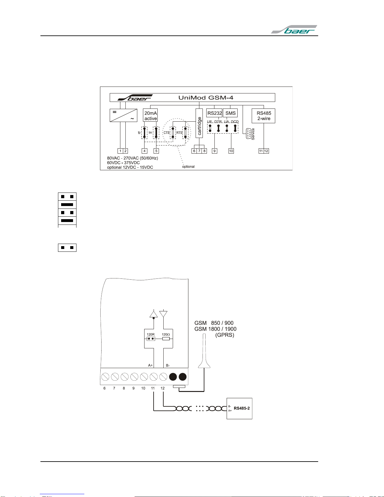
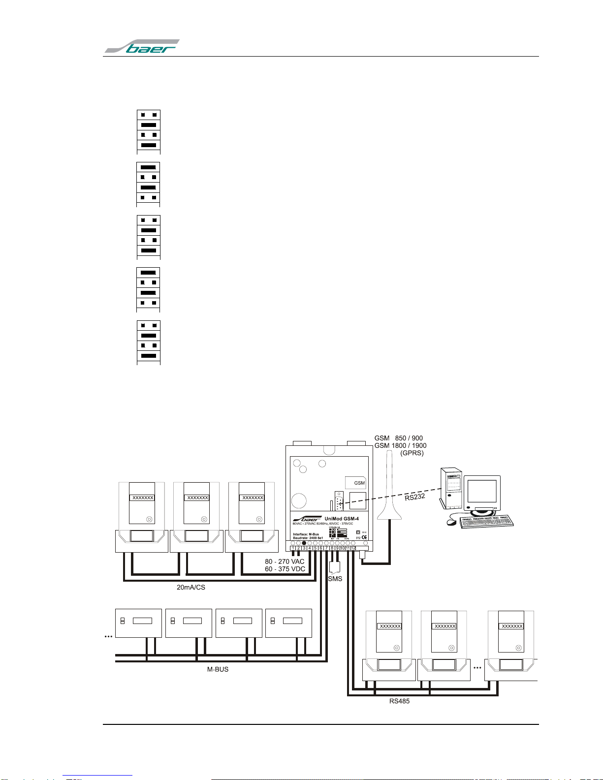
4Interfaces..........................................................................................................................8
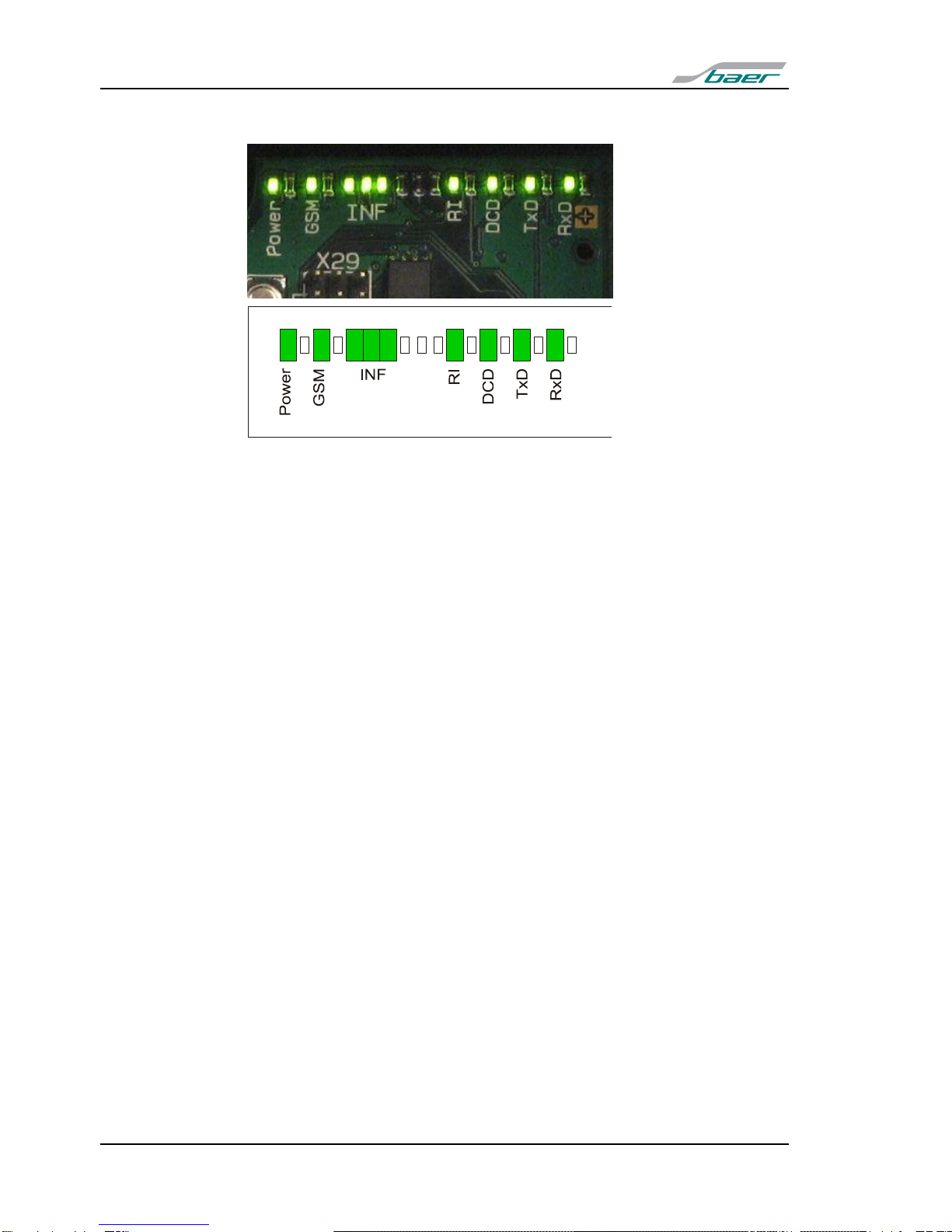
5Display............................................................................................................................10
6Installation Hints............................................................................................................11
7Programming the Modem..............................................................................................12
7.1 Testing the Connection...........................................................................................18
7.2 Parity Error (7E1)....................................................................................................18
8Additional Functions.....................................................................................................19
8.1 Reset......................................................................................................................19
8.2 Signal Quality .........................................................................................................20
8.3 SMS Function.........................................................................................................21
8.4 Automatic Baud Rate Adaption...............................................................................22
8.5 Temporary Baud Rate Switching ............................................................................25
8.6 GPRS: More PLMNs...............................................................................................26
8.7 GPRS: Fixed IP Address ........................................................................................27
8.8 GPRS: Dynamically Timeout ..................................................................................27
8.9 GPRS: Test Mode ..................................................................................................28
8.10 Firmware Update (Option) ......................................................................................28
9Technical Data ...............................................................................................................30
10 Inserting the Interface Modules....................................................................................32
11 Terminal Block...............................................................................................................33
12 Dimensions....................................................................................................................34

UniMod GSM-4
4

UniMod GSM-4
5
1 General
The world-wide GSM radio networks (GSM = Global System for Mobile
communication) provide besides digital voice communication the possibility
to transmit data. In this operation mode it is possible to send fax, data
(CSD: Circuit Switched Data connection), GPRS: General Packet Radio
Service) and short messages (SMS). The universal radio modem UniMod
GSM-4 is supposed for remote inquiry of measurement data of any kind,
especially however for telecounting applications.
The UniMod GSM-4 supports in the operation mode GPRS the meter data
communication according to DIN 43863-4 (IP-Telemetry).
1.1 Requirements
The UniMod GSM-4 can be used in any EGSM 850/900/1800/1900 MHz
network with an arbitrary number of providers. It requires however the in-
frastructure for operating mobile stations with 2 Watt (Class 4; 850/900
MHz) or 1 Watt (Class 1; 1800/1900 MHz) transmission power. The modem
supports an interface for 3V SIM cards. For communication a SIM card with
call number for 9600 Baud transmission is needed.
For the UniMod GSM-4 communication modules produced by internation-
ally renowned companies are used. These companies update their soft-
ware packages regularly and add or change features. The software
releases are continuously checked by the development department, but no
responsibility for this software releases can be taken over except of war-
ranty granted by the module producer.

UniMod GSM-4
6
2 Safety Precautions for the User
Aircraft safety
Cellular engines can interfere with an aircraft’s navigation system and its
cellular network. The use of UniMod GSM-4 on board aircraft is forbidden
by law. Failure to comply with this prohibition may lead to temporary sus-
pension or permanent cancellation of cellular engine services for the per-
son who infringes this prohibition and/or to legal action against said person.
Environments with explosive substances
a) Users are advised not to use the device in automotive service stations.
b) Users are reminded of the necessity to comply with restrictions regarding
the use of radio devices in fuel depots, chemicals plants and locations
where explosives are ignited.
Non-ionising radiation
As is the case with other mobile radio transmitters, operating personnel are
advised to use the device in the normal operating position only in order to
ensure optimum performance and safety. Avoid touching the antenna.
Personnel
Installation and repairing should be done by experienced personnel only.
Connecting to other devices
In order to connect the UniMod GSM-4 to another device please read the
device’s operation manual to obtain detailed information about safety. Don’t
connect devices, which are not approved by manufacturer.
Precautions in the event of loss/theft of the Cellular Engine and
the SIM card
If your UniMod GSM-4, your SIM card or both go missing, notify your net-
work operator immediately in order to avoid misuse.

UniMod GSM-4
7
3 Power Supply Unit
The modem is equipped with a built-in, low-loss switched power supply,
which enables it to operate on a wide-range AC or DC supply voltage.
80VAC to 270VAC (50/60Hz) or 60VDC to 375VDC
alternative (with additional board): 10VDC to 36VDC (0,8A)
or 20VDC to 72VDC
80VAC to 270VAC / 60VDC to 375DC
10VDC to 36VDC
Attention: NEVER remove the interface modules or the SIM card when the device
is powered! The card and especially it’s contact pads can be damaged
very easily by scratches or bending. Be careful when inserting or re-
moving it.

UniMod GSM-4
8
4 Interfaces
Communication is possible with many standard protocols, like SCTM,
LSV1, DLMS, IEC1107, IEC60870, M-Bus, Modbus (transparent reading)
etc.
The following internal (on-board) interfaces in UniMod GSM-4 are available:
RTS
tm
CTS
tp
20mA (CS, current loop) active for 4 devices max.
Can be enabled via jumpers „tp“ and „tm“. This interface supports “echo
suppression” and can be operated without load (terminal open).
120R
RS485 (2 wires).
Using the UniModSet program the user can determine the functionality of
the RS485 interface (2-wire or disabled). Set the “120R” Jumper for activa-
tion the 120 Ohm termination (if necessary).
RS232 (RxD, TxD, DTR, DCD, GND); for service only
RTS and CTS bridged;

UniMod GSM-4
9
In the UniMod GSM-4 modem an additional slot is available for another in-
terface module. For this slot the following module types are available (instal-
lation: see page 32):
RTS
tm
CTS
tp
20mA (CS, current loop) active (for 4 devices max.) or passive;
if the 20mA interface is active it must be operated either with a load or its
terminals must be short-cut.
RTS
tm
CTS
tp
RS232 (RxD, TxD, CTS, RTS, GND);
If RTS/CTS lines are used, the internal 20mA interface must be deactivated.
(Set jumper “RTS” and “CTS” instead of “tm” and “tp”.)
RTS
tm
CTS
tp
RS485 (2 wires);
RTS
tm
CTS
tp
RS485 (4 wires);
When the 4-wire interface is used, the internal 20mA interface must be de-
activated. (Set jumper “RTS” and “CTS” instead of “tm” and “tp”.)
RTS
tm
CTS
tp
M-Bus active (for 10 devices max.) or passive;
Please note: All interfaces are internally connected with each other. Therefore all
attached devices receive the same data from the interface. It must be
ensured that never two or more devices send data at the same time.
Example demonstrating different kinds of connection:

UniMod GSM-4
10
5 Display
Some of LEDs’display the current operating status of the modem and give in-
formation about the data transfer
Power signals, that the modem is supplied with power.
GSM - permanently off: power down mode
- 500 ms on / 500 ms off: Limited Network Service: No SIM card
inserted or no PIN entered, or network search in progress, or on-
going user authentication, or network login in progress
- 300 ms on / 2,7 s off: IDLE mode: The mobile is logged to the
network (monitoring control channels and user interactions); no
call in progress
- permanently on: CSD call: Connection to remote party
INF Information: 3 LEDs showing processor status and field strength.
Modem is ready for programming, data transmission and call
answering not before the leftmost INF-LED is on.
This happens
- in CSD mode (GSM dial-up connection): about 50 seconds after
“Power On”
- in GPRS mode: about 60 seconds after “Power On”
RI lights, when the modem rings
DCD - in CSD mode lights, when the modem has built a data link to re-
mote station
- in GPRS mode:
IPT or BAER: DCD lights, when the modem is logged to the
GPRS-Bridge
fixed IP address: DCD lights, when a remote modem has built a
data link to the UniMod GSM4;
TxD lights, when data is transferred from modem to target device (e.g.
meter)
RxD lights, when data is transferred from target device to modem

UniMod GSM-4
11
6 Installation Hints
The installation must be done in a way, that even in the case of cable break
no dangerous voltages are applied to touchable parts of the device includ-
ing the antenna. This can be accomplished e.g. by using cable ties and ap-
propriate shortening of the cables.
For installation insert the SIM card correctly and tighten it by using the
clamp of the card reader:
1) First open the clamp by shifting
the slide in the arrow’s direction
(OPEN). After release you can open
the lid and insert the SIM card as
shown in the picture. Please note
the position of the bevelled edge: it
must point at the upper-right side.
The golden contact pads have to
point downwards.
2) Insert the card until the lid can be
closed as shown in the picture. The
slide must be movable in this posi-
tion. Please note the position of the
bevelled edge. Now move the slide
against the arrow’s direction until it
clicks into place and the lid is
locked. The SIM card is now ready
to use.
3) After that connect the antenna to the UniMod GSM-4 using the FME
plug.
At last (important!) connect it to the supplying power.

UniMod GSM-4
12
7 Programming the Modem
Before installing the modem it has to be programmed in order to meet the
demands. The baud rate and data format for connecting the target device
and the transmission mode and transmission rates must be adjusted. On
delivery the following default parameters are active:
Data rate
9600 Bit/sec (if not differently mentioned)
Data format
7, Even, 1 (if not differently mentioned)
S0=1
This parameter setting determines the number of rings (here 1) before
automatic answering.
&D0
This parameter determines how the modem responds when circuit 108/2
(DTR) is changed from ON to OFF during data mode. With setting 0 the
modem ignores DTR.
E0
This setting determines whether or not the modem echoes characters
received from PC during command state. (0 = no echo)
Q0 V0
Information response: numeric code
+IPR=19200
Internal baud rate: don’t change this value!
+CBST=7,0,1
The modem selects the bearer service with automatic selection of the
speed, asynchronous, non-transparent mode to be used when data calls
are originated.
This configuration allows for reading standard meters according to VDEW2
(IEC 1107 / IEC62056-21). If you want to change this parameters, you need
a PC with terminal software UniModSet/MetcomTSet. Moreover experi-
ences with the Hayes AT modem command set are very recommended. To
establish connection between PC and modem you have to use the RS232-
Service interface (A) or a parametering adapter (B or C), Alternatively you
can use a converter („converter box“) in order to adapt the interfaces.
A) Service interface: Standard RS232 cable with 9 pole plug (Standard
RS232, Order No.: #4301).

UniMod GSM-4
13
B) The parametering adapter with RS232 interface, which can be plugged
instead of an interface module. This adapter can be ordered as accessory
(Order No.: #9177).
1) First set the switch to position
"GSM", as shown in the picture.
Then connect the 25 pole plug
(RS232) to the PC.
2) Disconnect the modem from the
supply (important!) and remove the
interface module..
3) Insert the 7 pole plug of the pa-
rametering adapter instead of the
interface module. The notch must
point in direction of the LED’s.
C) The parametering adapter with USB interface (Micro-USB Type A or B),
which can be plugged instead of an interface module. This adapter can be
ordered as accessory (Order No.: #12683).

UniMod GSM-4
14
Now you have to set your terminal program to the fixed, local data rate and
data format of the UniMod. (Default values: 9600 Bit/sec, 7,E,1) Use one of
the AT commands (e.g. ATS0?, ATI, AT&V) in order to check whether the
modem answers. If you see the answer on the screen, the interface is
working correctly.
B) or C) After programming switch off the UniMod and insert the interface
module carefully again.
►Simply typing „AT“ does not result in an answer, because the modem
is by default programmed not to send messages and echoes (Parame-
ters ATQ1 and ATE0).

UniMod GSM-4
15
Following some examples of AT commands (the answers depend upon the
respective firmware version):
Request
Answer
Description
at&v
DTE SPEED : 19200
DTE FORMAT : AUTO
GSM DATA MODE : Not Transparent
AUTOBAUD : +IPRxxx00=NO
COMMAND ECHO : E0=NO
RESULT MESSAGES : Q1=NO
VERBOSE MESSAGES : V1=YES
EXTENDED MESSAGES : X1=YES
LINE SPEED : F0=autodetect
CONSTANT DTE SPEED : YES
FLOW CONTROL OPTIONS : &K3=HW bidirect.
ERROR CORRECTION MODE : RLP
CTS (C106) OPTIONS : &B2=OFF while disc.
DSR (C107) OPTIONS : &S3=PHONE ready->ON
DTR (C108) OPTIONS : &D0=ignored
DCD (C109) OPTIONS : &C1=follows carrier
RI (C125) OPTIONS : \R1=OFF dur. off-hk
C108/1 OPERATION : &D4=NO
POWER SAVING ON DTR : +CFUN:1=NO
DEFAULT PROFILE : &Y0=user profile 1
Inquires current configuration
ati4
GE864-QUAD
Requests product information
at+cpin?
+CPIN: code
OK
SIM card inquiry
(ERROR: no/faulty SIM card
code = SIM PIN: waiting for PIN
code = READY: PIN active)
at+cpin=n
OK
Enter PIN, switches modem active.
e.g. AT+CPIN="1234" (if PIN is 1234)
at+clck=
"SC",0,"n"
OK
Disable PIN lock after power off. (n = PIN)
e.g. AT+CLCK="SC",0,"1234"
Attention: First enter PIN using AT+CPIN.
at+cops?
+COPS: 0,0,"operator"
OK
Inquire bearer service. Will be shown only,
when SIM card is active and antenna con-
nected.
at+cops=?
+COPS:
(2,"T-Mobile D",,"26201"),
(3,"Vodafone D2",,"26202"),
(3,"E-Plus",,"26203"),
(1,"o2 - DE",,"26207"),,
(0-4),(0,2)
List of available bearer services.
at+cbst=
s,n,e
OK
Choose transmission mode:
speed s=
0 - autobauding (automatic selection of the
speed, factory default)
1 - 300 bps (V.21)
2 - 1200 bps (V.22)
3 - 1200/75 bps (V.23)
4 - 2400 bps (V.22bis)
6 - 4800 bps (V.32)
7 - 9600 bps (V.32)
14 - 14400 bps (V.34)
65 - 300 bps (V.110)
66 - 1200 bps (V.110)
68 - 2400 bps (V.110 or X.31 flag stuffing)
70 - 4800 bps (V.110 or X.31 flag stuffing)

UniMod GSM-4
16
Request
Answer
Description
71 - 9600 bps (V.110 or X.31 flag stuffing)
75 - 14400 bps (V110 or X.31 flag stuffing),
name n=0 for asynchronous mode,
element e=0 for transparent or e=1 for non
transparent transmission
e.g.. at+cbst=0,0,1 (for autobauding, asyn-
chronous mode, non transparent)
at&f
OK
Set all parameters to factory defaults.
ats0=n
OK
This parameter setting determines the number
of rings (0 to 255) before automatic answer-
ing.
e.g. ats0=1 (Modem answers after first ring)
Attention: s0=0 disables automatic answer-
ing.
ats0?
001
OK
Returns the number of rings before automatic
answering.
at&w
OK
Saves the current parameter setting in the
user-defined profile. This settings are active
after every resumption of power supply.

UniMod GSM-4
17
Example: Programming UniMod GSM-4
Insert SIM card
Establish connection PC to modem (e.g. using the RS232 cable)
Switch on UniMod GSM-4, wait 50 to 60 sec: till first INF-LED is on
Start the UniModSet software
Read the equipment configuration:
Adjust the parameter
Hint: Mind to set the functionality of the internal RS485 interface correctly !
Write the configuration; after it: power off and on
Enable or disable the PIN via SIM-Card function
Check the signal quality and the internal temperature: possible only in CSD
mode:

UniMod GSM-4
18
7.1 Testing the Connection
For easier diagnosis of connection problems it is possible to display ex-
tended result codes for incoming call indication. In order to do this the fol-
lowing steps are necessary:
Activate result codes: Enter „ATQ0“, Modem reply: OK.
Activate extended result codes: „AT+CRC=1“, Modem reply: OK.
(„AT+CRC=0“ switches the extended codes off)
Call UniMod GSM-4 via data service (use appropriate telephone number).
Watch incoming call using terminal program.
Possible messages:
+CRING: REL ASYNC
incoming call has been correctly transmitted. That’s OK.
+CRING: VOICE
incoming call has been transmitted via „voice“ mode. Call rejected by mo-
dem. Remedy: set SIM-Card “Voice / Prepaid”:
+CRING: FAX
incoming call has been transmitted via „fax“ mode. Call rejected by modem.
7.2 Parity Error (7E1)
Depending on certain circumstances (software configuration, hardware
configuration of the PC, connection of the modem to the PC, operating sys-
tem,...) the communication software of your application might issue a mes-
sage like: wrong parity. In the most cases a switch of the UniMod GSM-4
data format from "7E1" to "8N1" is able to bring fast and easy help. Using
this configuration data retrieval from most meters is possible in the format
"7E1" and "8N1".
When data format „7E1“ is used the correct parity can be transmitted auto-
matically (Set tick ) or not (Setting ) .
If there are any further questions we are happy to help you.

UniMod GSM-4
19
8 Additional Functions
8.1 Reset
Optional it is possible to activate the time-controlled modem-reset. With this
turned on the modem (GE864-Module) is regularly deactivated by the inter-
nal firmware. After the reset it logs on to the PLMN (Public Land Mobile
Network) again. Activating is recommended when the field-strength of the
used GSM-net is very low. This functionality can be enabled using the Uni-
ModSet/MetcomTSet program.
The functionality is activated by the switches below the LEDs.
Jumper
Function
ab
Reserved, do not use !
par
Closed: internal programming by AT com-
mands: the internal CPU can optionally send
the AT commands to the GE864 module.
eep
Closed: Allow programming; changing of pa-
rameters by UniModSet program allowed.
Open: parameter memory (EEPROM) is write
protected.
pc2
Must be open always, used for internal proc-
essing.
RTS + CTS
Signals from interface module are connected
with terminals 4 and 5.
RS232: 4:=CTS, 5:=RTS
RS485/4 wires: 4:=Y+, 5:=Z-
Keep tp and tm open in this case!
tm + tp
Internal 20mA interface is connected with ter-
minal 4 (+) and 5 (-).
Keep RTS and CTS open in this case !
UE/DTR
Connect either RS232 DTR signal or control
input UE to terminal 9.
The UE input serves for sending a SMS or
triggering automatic baud rate adaption.
UA/DCD
Connect either RS232 DCD signal or control
output UA to terminal 10.
120R
Termination for RS485: 120Ohm
Delivery condition (standard):
UE
DTR
UA
DCD
120R
ab
par
eep
pc2
RTS
tm
CTS
tp
ab
par
eep
pc2
RTS
tm
CTS
tp
X40: UE, UA
X41: par, eep, tm, tp
X40
X41
UE
DTR
UA
DCD
120R

UniMod GSM-4
20
8.2 Signal Quality
When the modem operates in CSD mode (!) the INF-LEDs’show the cur-
rent field strength of the GSM signal. When the display is updated (every
three seconds) the first INF-LED flickers shortly. The second and third INF-
LED display the signal quality. Encoding see table below. (:LED on / :
LED off):
INF-LED
Signal level
Description
-99dBm to -113dBm
Bad signal quality, transmission may be disturbed.
-83dBm to -97dBm
Low signal quality;
-67dBm to -81dBm
Medium signal quality;
-51dBm to -65dBm
Good signal quality;
or
Undefined
(flashing)
No signal quality information available;
Check antenna
Undefined/GPRS
(flashing)
Modem logged in GPRS-Network: second and third
INF-LED flash alternately. In GPRS mode field
strength can not be displayed.
from version 81 up
-99dBm to -113dBm
-83dBm to -97dBm
-67dBm to -81dBm
-51dBm to -65dBm
After every reset: check for signal quality (once
only):
Bad signal quality: flashing every 4 seconds
Low signal quality: flashing 1Hz
Medium signal quality: flashing 2Hz
Good signal quality: flashing 3Hz
►During the connection and 60 seconds after it is the signalling dis-
abled!
Table of contents
Other Baer Modem manuals