Bajaj Auto Pulsar 150 User manual

Doc. No. 71112294 REV. 06, MAY 18
REV. 09, AUG 18

Foreword
Welcome to the Pulsar family!
You are now the proud owner of India’s No.1 sports bike. By No.1 we are talking about
unparalleled performance, superior technology and incredible market leadership that Pulsar today
enjoys. This makes the Pulsar you ride, unbeatable and unchallenged both on and off the road.
Before you ride out, please read this Owner's Manual carefully and familiarize yourself with the
operating mechanism, controls and maintenance requirements of your Pulsar. This will ensure you a
safe and trouble free ownership experience.
To keep your bike in perfect running condition and deliver consistent performance, we have
specially programmed the periodic maintenance services which includes 3 Free and subsequent
Paid services, as per the schedule contained in this booklet. We earnestly advise you to avail all
these services at any of our Bajaj Dealers or Authorised Service Dealers, who are well equipped
with all necessary facilities / genuine parts / oil and trained manpower to ensure the best care for
your Pulsar. Your Pulsar comes with a warranty of 5 Years or 75,000 Kms whichever occurs earlier
from the date of sale. For details please refer to “Warranty : Scope & Limits” given in this manual.
Should you require any additional information feel free to contact us on our helpline numbers or e-
To be a part of the Pulsarmania, visit and join the Pulsar fanpage on www.mypulsar.com
facebook: www.facebook.com/mypulsar
Rev up, shift gears and enjoy the Pulsar experience…
SERVICE DEPARTMENT
BAJAJ AUTO LIMITED

Description
1. Technical Specifications 1
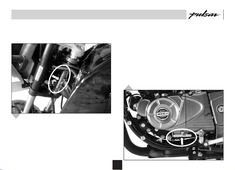
2. Identification Data 3
3. Location of Parts 4
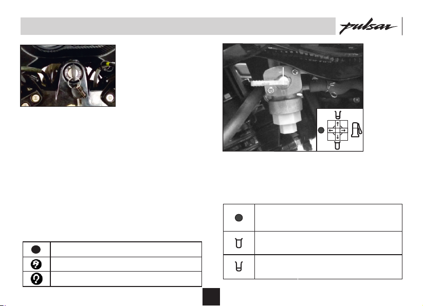
4. Steering cum Ignition lock 5
5. Fuel Tank Cap / Fuel Tap 6
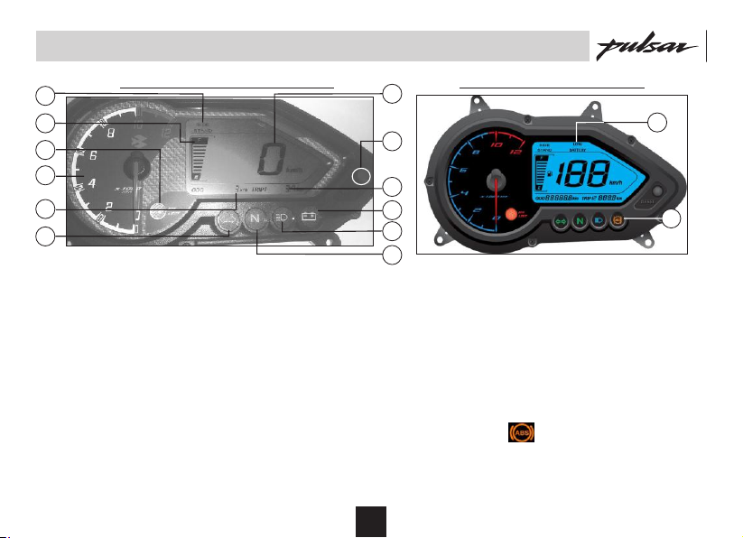
6. Speedometer Details 7
7. Control Switches 8
8. Removal & Fitment of Side Covers 10
9. Removal & Fitment Seat 12
10. Battery / Tool kit 13
11. Daily Safety Checks 14
12. How to ride your Bike 15
13. Safe Riding Tips 19
14. Engine Oil 20
15. Wheels - Tyre 21
16. Periodic Maintenance Information 22
17. Periodic Maintenance & Lubrication Chart 26
18. Free Service Guidelines 31
19. Non Use Maintenance 32
18. Delivery Certificate 33
19. Warranty Scope & Limit 34
20. Battery Warranty Card
Notice:
The description and illustration in this booklet
are not to be taken as binding on the
manufacturers. The essential features of the
type described and illustrated herein remaining
unaltered. Bajaj Auto Limited reserves the
right to carry out at any moment without
being obliged to bring this booklet upto-date
& to do modifications on the vehicle, parts or
accessories as may be convenient and
necessary.
Safety and Warning information :
Table of Contents
Caution : This indicates that a potential
hazard that could result in vehicle
damage. Follow the Advice provided with
the caution.
Warning : This indicates that a potential
hazard or injury to you or other persons &
to the vehicle can happen if advice
provided is not followed.

Pulsar 150
Engine : 4 stroke, Natural air cooled
Bore x Stroke : 56 mm x 60.7 mm
Engine Displacement : 149.5 cc
Compression Ratio : 9.5 +/- 0.5 : 1
Idling RPM : 1400 +/- 100
Max. Net Power : 10.3 Kw (14 Ps) at 8000 RPM
Max. Net Torque : 13.4 Nm at 6000 RPM
Ignition System : DC CDI
Spark Plug : Champion RG4HC, 2 Nos.
Spark Plug Gap : 0.7 to 0.8 mm
Transmission : 5 speed constant mesh.
Front Brake : Disc Brake
Rear Brake : Drum Brake
Fuel Tank Capacity
Full : 15 litres
Reserve : 3.2 litres
Usable Reserve : 2.0 litres
Dimensions :
Length : 2055 mm
Width : 755 mm
Height : 1060 mm
Wheel base : 1320 mm
Ground clearance : 165 mm
Pulsar 180
4 stroke, Natural air cooled.
63.50 mm x 56.40 mm
178.60 cc
9.5 +/- 0.5 : 1
1400 +/- 100
17.02 Ps at 8500 RPM
14.22 Nm at 6500 RPM
DC CDI
Champion RG4HC, 2 Nos.
0.7 to 0.8 mm
5 speed constant mesh.
Disc Brake
Disc Brake
15 litres
3.2 litres
2.0 litres
2035 mm
765 mm
1115 mm
1345 mm
165 mm
Pulsar 150 Twin Disc
4 stroke, Natural air cooled.
56 mm x 60.7 mm
149.5 cc
9.5 +/- 0.5 : 1
1400 +/- 100
10.3 Kw (14 Ps) at 8000 RPM
13.4 Nm at 6000 RPM
DC CDI
Champion RG4HC, 2 Nos.
0.7 to 0.8 mm
5 speed constant mesh.
Disc Brake
Disc Brake
15 litres
3.2 litres
2.0 litres
2035 mm
765 mm
1115 mm
1345 mm
165 mm
Technical Specifications
1
Note : • All dimensions are under UNLADEN condition.
• Above information is subject to change without any notice. • This vehicle complies to BS IV standards.
• AHO is government regulation.

Pulsar 150
Tyre Size Front : 2.75-17 41P, Tubeless
: 80/100-17 46P, Tubeless
Rear : 100/90-17 55P, Tubeless
2
Tyre Pressure Front : 1.75 kg/cm (25 PSI)
2
Rear (Solo) : 2.00 kg/cm (28.4 PSI)
2
Rear (Pillion) : 2.25 kg/cm (32 PSI)
Electrical System : 12 Volts DC
Battery : 12V - 4Ah VRLA
Head Lamp : 35/35W, HS1
Pilot Lamp : 5W Each 2 Nos.
Tail /Stop Lamp : LED
Turn Signal Lamp : 10W (4 nos.)
Neutral Indicator : LED
Hi Beam Indicator : LED
Turn Indicator : LED
Side Stand Indicator : LCD
Speedometer Illumination : LCD Amber
Low battery indicator : LED
ABS Indicator : Not applicable
Rear No. Plate Lamp : 3W
Horn : 12V DC
Vehicle Kerb Weight : Non ABS ABS
: 144 kg. Not applicable
Gross Vehicle Weight : 274 kg. Not applicable
Technical Specifications
2
Pulsar 180
90/90-17, 49P, Tubeless
120/80-17, 61P/S, Tubeless
2
2.00 kg/cm (28.4 PSI)
2
2.10 kg/cm (30 PSI)
2
2.25 kg/cm (32 PSI)
12 Volts DC
12V - 9 Ah MF
35/35W, HS1
5W Each 2 Nos.
LED
10W (4 Nos.)
LED
LED
LED
LCD
LCD Blue
LED for Non ABS, LCD for ABS
LED
3W
12V DC
Non ABS ABS
146 kg.
276 kg.
Pulsar 150 Twin Disc
90/90-17 49P, Tubeless
120/80-17, 61P/S, Tubeless
2
2.00 kg/cm (28.4 PSI)
2
2.10 kg/cm (30 PSI)
2
2.15 kg/cm (30.5 PSI)
12 Volts DC
12V - 4 Ah VRLA
35/35W, HS1
5W Each 2 Nos.
LED
10W (4 Nos.)
LED
LED
LED
LCD
LCD Blue
LED for Non ABS, LCD for ABS
LED
3W
12V DC
Non ABS ABS
144 kg.
274 kg.

Identification Data
The Frame and Engine serial numbers are used to register the motorcycle. They are the unique
alpha-numeric codes to identify your particular vehicle from others of the same model and type.
Frame Number Location
On Side of Steering Tube
(Alpha-Numeric - 17 Digits)
Engine Number Location
On LH Side Crankcase Near Gear
Change Lever (Alpha-Numeric - 11 Digits)
3

This photograph is of Pulsar 180 Non ABS
Location of Parts
4
Front Fork
Fuel
Tank
Rear
Shock Absorber
Manual
Choke
Grab
Handle
Pillion
Foot Rest
Engine Oil Level
Inspection Window Front Disc Brake
Rear
Disc Brake
Accelerator
Grip

Steering cum Ignition Lock / Fuel Cock
To Lock the Steering : To lock the steering,
turn the handle bar to the left or right. Push &
release the key. Turn the key to “LOCK”
position and remove the key.
To Unlock the Steering : To unlock steering,
insert the key in steering cum ignition lock &
turn it clockwise to “OFF” or “ON” position.
Key : A common key is used for ‘Steering
cum Ignition lock’, ‘Fuel tank cap’ & ‘Side
cover lock’.
Steering cum Ignition Lock :
It has three positions.
LOCK: Steering locked. Ignition OFF.
OFF: Steering unlock. Ignition OFF.
ON: Steering unlock. Ignition ON.
5
Fuel Tap
Fuel Tap
Fuel tap lever has following positions.
OFF : When fuel supply is to be
cut off.
ON : When fuel level is above
reserve position.
RES : When fuel level is below
reserve position.
Fuel Tap

Fuel Tank Cap
• To open the fuel tank cap, open the flap.
Insert the key in the lock and turn it
clockwise and lift fuel tank cap.
• To lock the ‘Fuel Tank Cap’ insert the key
in the lock and turn it clockwise and press
fuel tank cap. ‘Click’ sound ensures cap is
fully locked.
Fuel Tank Cap / ABS System
6
Fuel Tank
Cap
Precaution :
Dont attach metallic ‘Key chain’ as it may damage
paint of petrol tank.
Single Channel ABS unit for Front brake is fitted on
this vehicle.
ABS System Information:
Always maintain a safe distance between you and
objects ahead. Vehicle speeds should always be
reduced during extreme road conditions. The braking
distance for motorcycle equipped with an anti-lock
braking system may be longer than for those without it
on rough road conditions. During these conditions the
vehicle should be driven at reduced speeds.
When you apply Front brake under conditions which
may lock the wheels, you feel a corresponding
sensation (pulsation) in Front brake lever. This is
normal and it means your ABS is active.
Also it is recommended to use both front & rear brakes
simultaneously.
Always slow down when cornering. The anti-lock brake
system cannot prevent accidents resulting from
excessive speeds.

ABS Speedometer assembly
Speedometer Details - ABS/Non ABS
7
1. Side Stand Indicator : It glows when Side stand is
down & igntion switch is ‘ON’.
2. Fuel Level Indicator : Fuel level indicator shows
available fuel in fuel tank. Tank symbol glows when
petrol level in tank reaches reserve level
3. Engine Rev Indicator :It blinks when engine RPM
cross 9000 RPM mark.
4. Tachometer Dial : It shows engine speed in RPM.
5. Odometer : The Odometer shows the total distance
that the vehicle has accumulated.
6. Turn Indicator (LH & RH) : When Turn signal switch
is turned to L/R, Turn indicator - LH or RH will flash.
7. Speedometer:Vehicle speed will be displayed digitally
8. Trip Meter Reset Button : Both trip meters can be
reset to zero by pressing the button.
9. Trip Meter : The Trip meter shows the distance
traveled since it was last reset to zero.
10. Battery Indicator : It shows battery needs charging
11. Hi Beam Indicator : It glows when Headlight is ‘ON’
& Hi beam is selected with engine running.
12. Neutral Indicator : It glows when transmission is in
Neutral & Ignition switch ‘ON’.
13. Bajaj Logo : Bajaj logo flying ‘B’ glows.
14. ABS Indicator ( ): With Ignition switch ON the
ABS indicator glows. W hen vehicle speed is more than
5 Km/h the ABS indicator goes off, if this indicator
glows while vehicle is running, it means there is
problem in ABS unit.
2
5
6
4
3
1
10
11
8
9
12
7
10
14
Non ABS Speedometer assembly

Control Switches
8
C. Horn Button : ( ) Press button for
sounding horn.
D. Pass Switch : Press the switch to flash
the head light. It is used to give signal to
vehicles coming from opposite side while
overtaking.
Left Handle Bar Switches
A. High/Low beam switch : When headlight
is ON, High or Low beam can be selected
with this switch. Hi beam indicator light
located on Speedo console will light up
when high beam is selected.
: High Beam : Low beam
B. Turn Signal Switch : When the turn signal
knob is turned to Left ( ) or Right ( )
respective indicator will start blinking, to
stop blinking push the knob in & release.
D
A
B
C

9
Control Switches
Hi/Low beam Headlamp Effect of
Switch Status Pass Switch
Low beam Low beam ‘ON’ Hi beam ‘ON’
Hi beam Hi beam No change
‘ON’
AHO Feature (Automatic Headlight ‘ON’)
There is no ‘Light switch’ on RH control
switch.
Ignition switch ‘ON’ Speedometer illumination
Engine ‘OFF’ Tail lamp, Number
Plate Lamp, Pilot
Lamp & Control Switches
Illumination will get ‘ON’
Effect of pressing In addition to above
‘Pass Switch’ Hi-beam will get ‘ON’
Ignition switch ‘ON’ & Engine Running
Speedometer illumination, Tail lamp, Number Plate
Lamp, Pilot Lamp & Control Switches Illumination will
get ‘ON’
in addition to above, headlamp will get on as given
below.
E
Right Handle Bar Switches
E. Starter Button :
Starter button operates the electric starter.
It is recommended to start the engine with
the transmission in neutral.
Vehicle in Gear - Press clutch lever &
operate starter button to start the engine.
F. Engine Kill Switch :
The engine kill switch is used for switching
ON & OFF the engine.
: Engine OFF
: Engine ON
F

Removal & Fitment of Side Cover LH / RH
Fig. Side Cover LH Fig. Side Cover RH
CAUTION : Remove cover as described
above, Otherwise the lugs may break.
10
Removal of Side Cover LH
• Insert key into the cover lock & turn
clockwise and pull the ‘Side Cover’ out
from the bottom.
• Pull front portion of ‘Side Cover’ to release
its Lug from hole (A) of ‘Fuel Tank’.
• Slide the ‘Side Cover’ forward (towards the
engine) to release slot provided on its rear
end from ‘bracket with rubber cap’ (B)
provided on ‘Chassis’.
• Take out side cover.
Removal of Side Cover RH
• Remove the screw (C) securing the ‘Side
Cover RH’.
• Pull front portion of ‘Side Cover’ to release
its Lug from hole (A) of ‘Fuel Tank’.
• Slide the ‘Side Cover’ forward to release
slot provided on rear end of ‘Side Cover’
from ‘bracket’ (B) provided on ‘Chassis’.
• Take out side cover.
A
B
C

Removal & Fitment of Side Cover LH / RH
11
Fitment of Side Cover LH
• Match slot provided on rear end of ‘Side
Cover’ with bracket (A) provided on
‘Chassis’ and slide ‘Side Cover’ backward
(towards Tail lamp).
• Match Lug provided on front portion of
‘Side Cover’ with hole (B) provided on ‘Fuel
Tank’ and press ‘Side Cover’ inside.
• Match the lock plate of ‘Side Cover’
properly with bracket on ‘Chassis’ and
rotate key in clockwise direction to lock.
Fitment of Side Cover RH
• Match slot provided on rear end of ‘Side
Cover’ with bracket (A) provided on
‘Chassis’ and slide ‘Side Cover’ backward
• Match Lug provided on front portion of
‘Side Cover’ with hole (B) provided on ‘Fuel
Tank’ and press ‘Side Cover’ inside.
• Match ‘Side Cover RH’ properly with
bracket provided on ‘Air filter assly’ & fix it
with Screw.
CAUTION : Fit cover as described above
to ensure proper fitment.
A
B

Removal & Fitment of Seat
12
Removal of Seat- Front & Rear
(Pulsar 150 Twin Disc / 180)
• Remove ‘Side Cover’ LH.
• Pull rear seat lock cable (A) & remove ‘Rear Seat’
• Similarly pull the front seat lock cable (B) & remove
‘Front Seat’.
CAUTION: Always remove Rear seat first.
A
BLock
Lug Lug
Lock
Fitment of Seat- Front & Rear
(Pulsar 150 Twin Disc / 180)
• Both the seats can be fitted by matching their lug
with the respective lock & pressing down the lug into
lock.
CAUTION : Always fit Front seat first.
Fig. CSeat Release Cable Fig. B
Removal of Seat assembly complete
• Remove ‘Side Cover’ LH.
• Pull seat lock cable (A) & remove the seat complete.
For Pulsar 150 follow procedure as given below
Fitment of Seat assembly complete
• The seat assembly can be fitted by matching its lug
with the lock & pressing down the lug into the lock.
For Pulsar 150 follow procedure as given below

Battery / Tool Kit
13
Tool Kit Location
• It is located below the battery.
• 2 rubber straps are provided to hold the
tool kit.
First Aid Kit Location
• First aid kit is to be stored in seat cowl.
Battery
• It is located inside the ‘Side Cover’ LH.
• Always maintain electrolyte level in each
cell between max and min level lines.
• Always keep a watch on battery charge
level indicating icon, if it flashes (indicates
battery is in low charged condition), show
the vehicle to authorised BAL dealer.
CAUTION : Do not drive/run vehicle in
battery disconnected condition. It may
lead to damage of electrical / electronic
components.
CAUTION : Always fit rubber strap for
locking tool kit.
Tool Kit
Battery
Pulsar 180 Pulsar 150 / 150 Twin Disc

Daily Safety Checks
• Brake Pedal Play-Drum Brake 15 to 20mm
Disc Brake-Fixed
• Wear lining Indicator within usable range.
No brake dragging, applicable to drum
brake vehicles.
• Brake Fluid level above MIN mark
provided on reservoir, applicable to disc
brake vehicle.
• Drive Chain slack of 20 to 30 mm
adequately lubricated.
• Function of all lights & horn
• Clutch lever play - 2 to 3 mm
• Smooth steering movement without
restriction.
• Both stand return to their fully up position.
• Correct inflation pressure in both tyres
Adequate tyre tread depth - no cracks /
cuts.
• Correct rear viewing span adjustment of
mirror.
Before riding motorcycle be sure to check
following items. Please give proper importance
to these checks and perform all of them
before riding motorcycle.
If any irregularities are found during these
checks, refer to the Maintenance chapter &
see your dealer for the action required to
return the motorcycle to a safe operating
condition.
Warning : Failure to perform these
checks every day before you ride may
result in serious damage or severe
accident.
• Enough fuel level for planned distance of
journey. No fuel leakage in fuel lines.
• Engine oil level (between upper and lower
level mark)
• Throttle cable play of 2 ~ 3 mm. Smooth
operation and positive return to closed
position,
14

How to Ride Your Bike
15
Starting The Engine :
• Turn the fuel tap knob to ‘ON’ or ‘RES’
position.
• Switch ‘ON’ ignition & ‘Kill Switch’
• Confirm that transmission is in neutral.
• Keep throttle completely closed, press starter
button “ ” to start the engine.
• Release starter button as soon as engine
starts.
Moving Off :
• Check that Center/Side stand is up.
• Depress the clutch lever.
st
• Shift into 1 gear.
• Open the throttle and release the clutch
lever slowly and simultaneously.
• As the clutch starts to engage, open the
throttle a little more, giving the engine just
enough rpm to keep it from stalling.
Caution : Do not operate the starter
continuously for more than 5 seconds
otherwise battery would get discharged.
Wait 15 sec. between each operation of
the starter which will facilitate battery to
recover.
Note : The motorcycle is equipped with a clutch
switch. This switch ensures that engine does not
start if the transmission is in gear.
However, the engine can be started in any
gear if the clutch lever is pressed.
Note : Do not let the engine idle longer than 3
minuets otherwise it will overheat.
• If the engine is cold or when starting for first
time, use choke ‘ ’for quick starting.
• When the engine is
warmed up enough to
idle without using
choke, return the
choke to OFF
position.
Manual Choke
ON
OFF

Braking :
• Close throttle completely, leaving clutch
engaged (except where shifting gears) so
that engine braking will help slow down
motorcycle.
• Shift down one gear at a time so that you
are in Neutral when you come to a complete
stop.
• Front brake is to be used to get maximum
braking performance.
• Rear brake is to be used when more de
celeration is required.
• When stopping, always apply both brakes at
the same time. De-clutch as necessary to
avoid engine stalling.
th th
From 5 to 4 Gear
th rd
From 4 to 3 Gear
rd nd
From 3 to 2 Gear
nd st
From 2 to 1 Gear
45 km/h
35 km/h
25 km/h
15 km/h
Recommended Speed for Shifting Down
Warning : When shifting down to lower
gear, do not shift at such high speed that
engine rpm jumps excessively. This may
cause engine damage, & rear wheel may
skid. Downshifting should be done at
recommended speeds as shown in table.
16
How to Ride Your Bike
Shifting Gears :
• Close throttle & depress the clutch.
• Shift into next higher or lower gear.
• Open the throttle and release the clutch
lever slowly and simultaneously.
Gear Shifting Lever
Gear Shifting
Pattern

Stopping the Vehicle :
• Close the throttle completely.
• Shift the transmission into neutral.
• Bring the vehicle to complete stop.
• Turn the ignition switch off.
Parking the Vehicle :
• Support the motorcycle on a firm level
surface with the center or side stand.
• Lock the steering.
Running IN
Proper running-in is important for the better
life & trouble free performance of the vehicle.
• During first 2000 kms running-in period do
not exceed following speed limits.
• Always keep the speed below the limits
mentioned in the table.
• Do not race the engine excessively.
• Do not start moving or race the engine
immediately after starting. Run the engine
for a minute at idle speed to give the oil a
chance to workup into the engine.
How to Ride Your Bike
17
Kms 1st 2nd 3rd 4th 5th
0 - 1000 10 20 30 35 45
1000 - 2000 15 30 40 45 55
CAUTION : Do not park on a soft or steeply
inclined surface or the motorcycle may fall over.
Whenever vehicle is falls down, remove plug of 'Y
connecter drain tube' & drain out accumulated
petrol
Location - Near Main Stand
'Y connecter drain
tube plug’
This manual suits for next models
1
Table of contents
Other Bajaj Auto Motorcycle manuals

Bajaj Auto
Bajaj Auto The Invincible V12 User manual

Bajaj Auto
Bajaj Auto Boxer BM 100 User manual

Bajaj Auto
Bajaj Auto pulsar NS125 User manual

Bajaj Auto
Bajaj Auto DTS-i Discover 110 CBS User manual

Bajaj Auto
Bajaj Auto Pulsar 200 NS User manual

Bajaj Auto
Bajaj Auto CT100B User manual

Bajaj Auto
Bajaj Auto RE 4-stroke User manual

Bajaj Auto
Bajaj Auto CT 100 User manual

Bajaj Auto
Bajaj Auto Chetak 4 stroke 003002CL Operating and maintenance manual

Bajaj Auto
Bajaj Auto Pulsar RS 200 User manual