Baker Hughes Flexflo 887 User manual

Flexo™
Model 887 Surge Reliever
Instruction Manual (Rev.C)
Baker Hughes Data Classication : Public

ii | Baker Hughes Copyright 2020 Baker Hughes Company. All rights reserved.
THESE INSTRUCTIONS PROVIDE THE CUSTOMER/OPERATOR WITH IMPORTANT PRO-
JECT-SPECIFIC REFERENCE INFORMATION IN ADDITION TO THE CUSTOMER/OPERATOR’S
NORMAL OPERATION AND MAINTENANCE PROCEDURES. SINCE OPERATION AND MAINTE-
NANCE PHILOSOPHIES VARY, BAKER HUGHES COMPANY (AND ITS SUBSIDIARIES AND AF-
FILIATES) DOES NOT ATTEMPT TO DICTATE SPECIFIC PROCEDURES, BUT TO PROVIDE BA-
SIC LIMITATIONS AND REQUIREMENTS CREATED BY THE TYPE OF EQUIPMENT PROVIDED.
THESE INSTRUCTIONS ASSUME THAT OPERATORS ALREADY HAVE A GENERAL UNDER-
STANDING OF THE REQUIREMENTS FOR SAFE OPERATION OF MECHANICAL AND ELEC-
TRICAL EQUIPMENT IN POTENTIALLY HAZARDOUS ENVIRONMENTS. THEREFORE, THESE
INSTRUCTIONS SHOULD BE INTERPRETED AND APPLIED IN CONJUNCTION WITH THE
SAFETY RULES AND REGULATIONS APPLICABLE AT THE SITE AND THE PARTICULAR RE-
QUIREMENTS FOR OPERATION OF OTHER EQUIPMENT AT THE SITE.
THESE INSTRUCTIONS DO NOT PURPORT TO COVER ALL DETAILS OR VARIATIONS IN
EQUIPMENT NOR TO PROVIDE FOR EVERY POSSIBLE CONTINGENCY TO BE MET IN CON-
NECTION WITH INSTALLATION, OPERATION OR MAINTENANCE. SHOULD FURTHER INFOR-
MATION BE DESIRED OR SHOULD PARTICULAR PROBLEMS ARISE WHICH ARE NOT COV-
ERED SUFFICIENTLY FOR THE CUSTOMER/OPERATOR’S PURPOSES THE MATTER SHOULD
BE REFERRED TO BAKER HUGHES.
THE RIGHTS, OBLIGATIONS AND LIABILITIES OF BAKER HUGHES AND THE CUSTOMER/
OPERATOR ARE STRICTLY LIMITED TO THOSE EXPRESSLY PROVIDED IN THE CONTRACT
RELATING TO THE SUPPLY OF THE EQUIPMENT. NO ADDITIONAL REPRESENTATIONS OR
WARRANTIES BY BAKER HUGHES REGARDING THE EQUIPMENT OR ITS USE ARE GIVEN
OR IMPLIED BY THE ISSUE OF THESE INSTRUCTIONS.
THESE INSTRUCTIONS ARE FURNISHED TO THE CUSTOMER/OPERATOR SOLELY TO AS-
SIST IN THE INSTALLATION, TESTING, OPERATION, AND/OR MAINTENANCE OF THE EQUIP-
MENT DESCRIBED. THIS DOCUMENT SHALL NOT BE REPRODUCED IN WHOLE OR IN PART
WITHOUT THE WRITTEN APPROVAL OF BAKER HUGHES.

Flexo 887 Series Surge Reliever Manual | 1
Copyright 2020 Baker Hughes Company. All rights reserved.
Scope
This manual provides instructions for installing, operating,
maitianing and determining the Jacket Pressure Set Point
(JPSP) for all sizes of Flexflo surge relievers.
Product Description
The Flexflo Surge Reliever consists of a slotted metal Core over
which a flexible rubber tube is installed. Tubes each have a
maximum allowable differential pressure rating, based on ASME
Class ratings, and they are molded in a number of different rubber
compounds to meet different applications. The Core has two sets
of openings or slots arranged around the outer circumference of
the Core. The inlet slots are separated from the outlet slots by a
metal barrier. The volume enclosed by the Body sleeve and the
outside surface of the Liner is a pressure chamber known as the
Jacket space. A ported metal Liner is located around the Tube
and prevents over expansion of the Tube. The volume between
the tube and the Liner is known as the Annular volume. The
Jacket and the Annular volume are connected by the ports in the
Liner, and together make up the Total Volume, which is charged
with compressed, dry gas (not with liquid).
Principles of Operation
(Refer to Figure 1 to identify parts).
When the inlet pipeline pressure (upstream of the Surge
Reliever) plus the added pressure required to over come
the Tube material’s natural resistance to expand (the Tube’s
Minimum Differential pressure or DF Minimum) exceeds the
Jacket Pressure Set Point of the Flexflo Surge Reliever, the
Flexflo will start to open and start to relieve the line pressure
upstream of the Flexflo Surge Reliever.
Table Of Contents
Product Description ..................................................................................................................1
Surge Reliever Markings...........................................................................................................1
Principles of Operation .............................................................................................................1
Installation ..................................................................................................................................2
Set Jacket Pressure Set Point ..................................................................................................4
Tube Differential Pressure ........................................................................................................5
Field Assembly and Disassembly ............................................................................................6
Product Support ........................................................................................................................10
Field Disassembly and Reassembly Tables ............................................................................11
Flow
Liner
Tube
Annular
Volume
Jacket Volume
Short Length
is Down-
stream End
Body Sleeve
Jacket at Loading Port
Surge Reliever Markings
Figure 1 - Partial Cutaway of Flexflo Surge Reliever
When the pressure at the inlet of the exceeds the Jacket
Pressure Set Point pressure by the Tube’s DF Minimum
pressure, the valve will start to open. Fluid at the inlet will be
directed up through the upstream slots in the Core, between
the inner surface of the Tube and around the outside surface
of the Core’s Barrier, down into the downstream slots into the
downstream surge line. Minor surges may be absorbed by just
the action of the Tube expanding slightly relieving line pressure
without releasing fluid from the upstream pipeline. Reaction time
for the Surge Reliever is very rapid, in the range of milliseconds.
The additional volume of compressible gas in the Jacket space
allows rapid expansion of the Tube.
Note: Temperature variations will cause the Jacket pressure
to vary. See temperature changes Page 2.

2 | Baker Hughes Copyright 2020 Baker Hughes Company. All rights reserved.
Installation
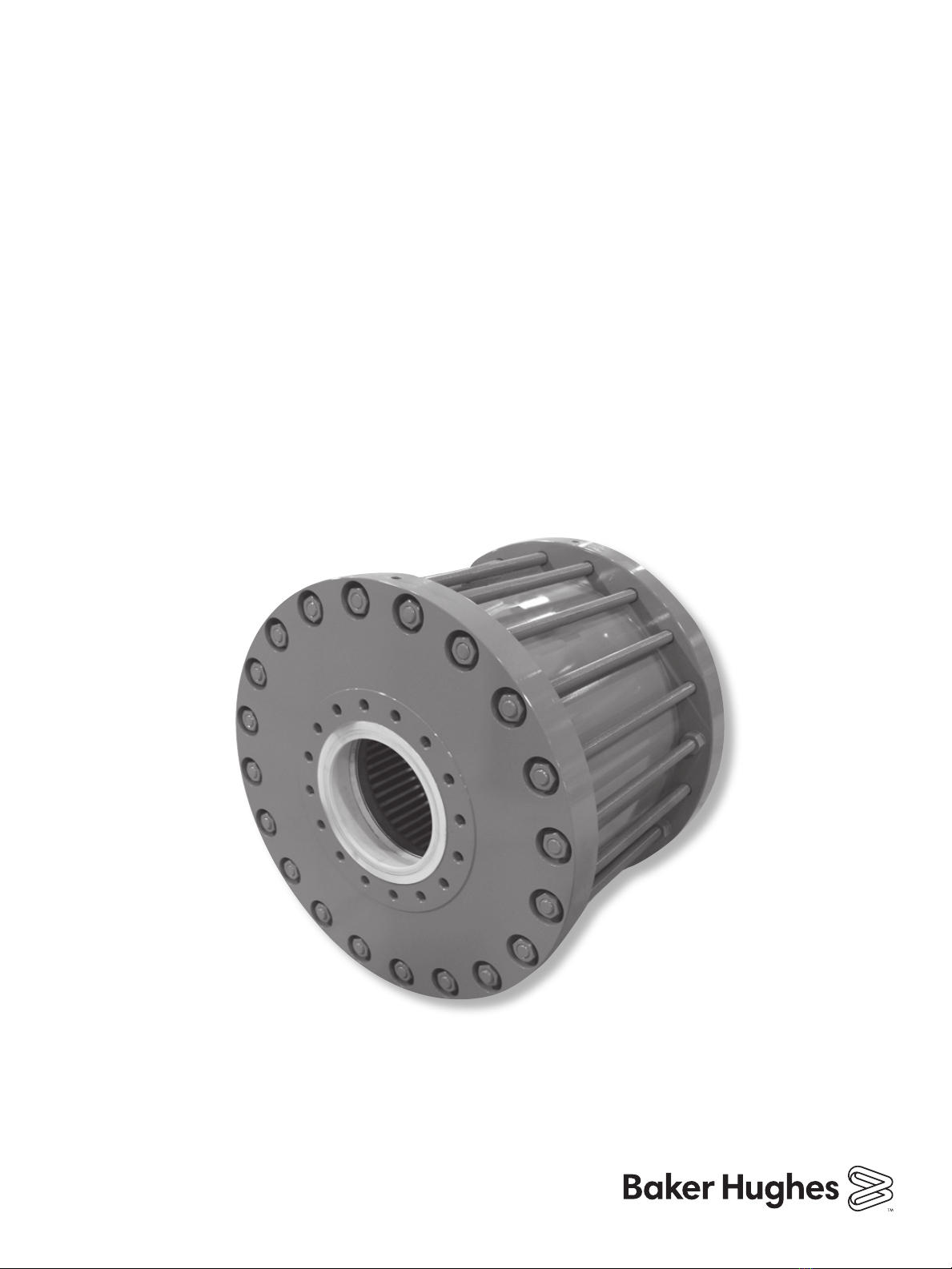
1) The Flexflo Surge Reliever may be installed in either a
vertical or horizontal line. Flow must be in the direction of
the flow arrows.
2) The pressure source for charging the Jacket and Annular
volume must be dry nitrogen, natural gas, or compressed air
at a pressure higher than the desired pressure in the Jacket
Space (the Jacket Pressure Set Point).
DO NOT USE OXYGEN or liquids to pressurize the
Flexo’s Jacket Space.
3) All connections for the Jacket supply gas must have no
leaks.
4) The range of the Jacket Pressure gauge should be
approximately twice the desired Set Point Pressure.
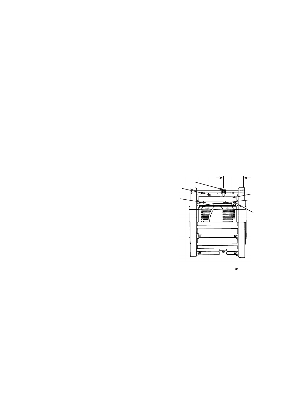
5) Allow sufficient space for accessing and servicing the Flexflo
Surge Reliever with lifting equipment.
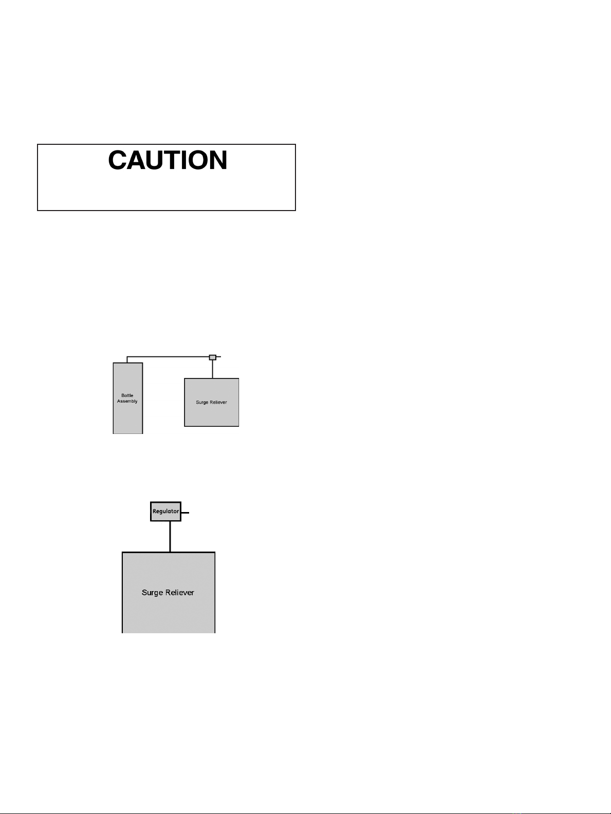
Methods to adjust and hold pressure in the jacket
A. Bottle assembly (See Figure 2). The bottle assembly
provides a convenient method to hold pressure in the jacket
See adjusting pressure with a bottle assembly on page 3.
Figure 2
B. See figure 3. With a pressure source at a higher pressure a
pressure regulator can regulate pressure to the jacket. See
instruction W-887-15LH-B00-1 if this method is chosen.
Figure 3
Temperature changes
Temperature changes in the jacket will change the pressure
when the surge reliever will open. This is important to consider
because the surge reliever could open at a higher pressure than
desired. A few things should be considered for the day to night
and week to week changes in temperature around the surge
reliever.
Ways to deal with temperature changes:
1. Chosen Jacket pressure could be low enough that even with
temperature and pressure changes the surge reliever will
open when needed.
2. A method could be provided by the customer to keep the
temperature around the surge relieve constant.
3. Bottle assembly can be buried in the ground.
4. Shade the surge reliever and bottle assembly.
5. Method B with a hard adjustable regulator could be used.
The pressure regulator can remove excess pressure or add
pressure as needed to the jacket however it also will change
pressure over time so adjustments will be needed. See
instruction W-887-15LH-B00-1 if this method is chosen.
Adjusting pressure with a bottle assembly Installation:
1. Bottles assemblies are coated to allow them to be buried in
the ground with only the top of the bottle(s) exposed. The
purpose of embedding the bottles in the ground is to support
the bottles and to stabilize the temperature of the bottles. If
the Bottles are not buried, the Bottle Assembly should be
secured properly and protected from damage to the bottle(s)
or the pressurized lines.
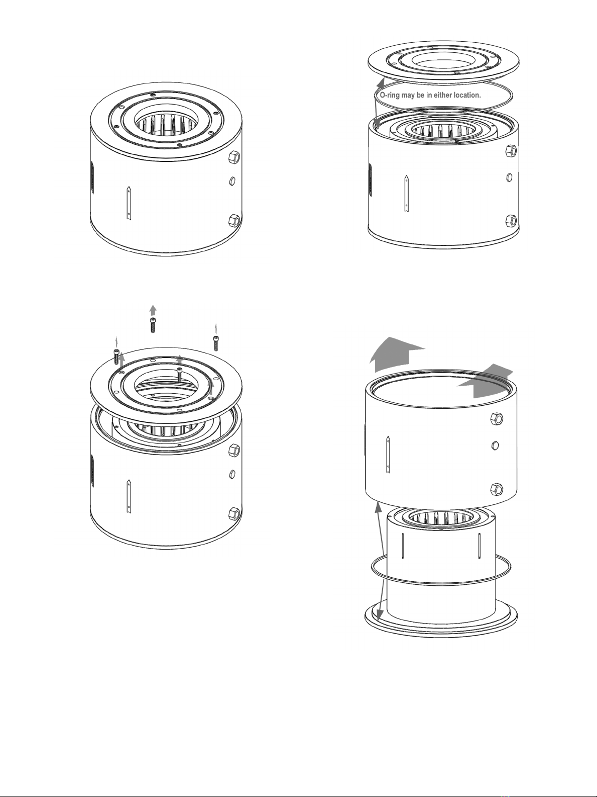
2. The 1/2” MNPT end, the end with the O-ring, of the Jacket
Connector Assembly, see Figure 4, will be threaded into the
1/2” FNPT Jacket Port of the surge reliever.
a. Clean and inspect the mating surfaces, the O-ring,
and O-ring sealing surfaces for any damage, debris,
or packing material that may interfere with proper
installation or with a pressure tight seal.
b. Thread the 1/2” MNPT end of the Jacket Connector
Assembly into the Jacket Port until it just bottoms out.
Do not tighten. Position the three 5/32 hex head valves
(labeled Supply, Vent, and Cylinder) so they can easily
be adjusted, but will not collect water; and position the
pressure gauge (if equipped) so that it can be easily
read and will not collect water. Tighten the 1-1/4” Lock
Nut with a 1 1/4” wrench against the body of the surge
reliever while holding the body of the Jacket Connector
Assembly. Maintain the proper position of the gauge
and valves.
3. A separate pressure supply source will be required to charge
the Jacket chamber/recharge the Bottle Assembly. When
not in use, insert a 1/4” MNPT pipe plug into the Charging
Supply Connection. The Pipe plug is recommended but not
required.
4. Install the tubing from the Cylinder Connection to the open
tube fitting of the Bottle Assembly. Secure the tubing so that
it is protected from damage and vibration.
5. Visually inspect the system for any open ports, loose
connections, or damaged tubing. Plug or tighten any open
ports or loose connections. Replace any damaged tubing.
6. Loosen the supply and cylinder lock nuts and back out the
threaded nut collars approximately 1 turn.

Flexo 887 Series Surge Reliever Manual | 3
Copyright 2020 Baker Hughes Company. All rights reserved.
Pressurize/Charge the 888 Bottles:
1. Using an external pressure source to charge/recharge the
Bottle system.
a. Remove plug if needed from Charging supply
connection. Connect an external pressure source with
either very dry air or Nitrogen Gas to the Charging
Supply connection.
b. Open the valve to the external pressure source.
c. Slowly open the Cylinder Valve and the Supply Valve to
pressurize the Bottles and the Jacket Space.
d. Allow the Pilot Bottle system and the Jacket to charge
up to the desired set point pressure, if no leaks in the
system are detected. Close only the Supply Valve
once the desired Jacket pressure and the Bottles are
pressurized to the desired set point.
e. Snug the two threaded Collars and tighten the two Lock
Nuts to 8 ft-lbs (10.8 Nm).
Cylinder
Connector
Charging Supply
Connector
Figure 4 - Jacket Assembly
Flexflo Surge Reliever Adjustment Procedure:
Gauges must be rated for higher than the maximum pressures
required at both the Inlet and the Jacket Loading ports of the
Flexflo Surge Reliever.
1. Increase the pressure in the Jacket Loading port to a
pressure slightly (approximately 50 psig or 3.45 barg) above
the desired Relief Set Point pressure (the Line pressure
where the Flexflo Surge Reliever will start to open and relieve
the upstream pipeline pressure). If necessary increase the
Line pressure at the same time as the Jacket pressure.
Do not exceed the maximum rated differential pres-
sure of the Tube at any time. Refer to the nameplate
for the maximum differential pressure rating for the
Flexlo tube.
2. Gradually apply and maintain the desired Line pressure to
the inlet of the Flexflo Surge Reliever.
3. From the Tube Differential Pressure Table obtain:
a. the full open differential pressure DF Maximum for the
size and tube material in use at the applications coldest
temperature.
b. The differential pressure where the Flexflo Surge
Reliever tube begins to flow DF Minimum for the size
and tube material in use at the applications coldest
temperature.
Note: The Tube Differential Pressure Table informationshows
average values and variations of+/- 5% can be expected.

4 | Baker Hughes Copyright 2020 Baker Hughes Company. All rights reserved.
Jacket Pressure Set Point
pressure for a required flow
rate can now be determined
by either of two methods:
Do not exceed the maximum rated diffential pressure
of the Tube at any time.
A. Tube Differential chart adjustment method:
Example:
1. A 12”, ASME Class 600, 887 Surge Reliever, with a
Nitrile 846 Tube is connected into a pipeline where
the fluid (water) is just above freezing, 32 degrees
Fahrenheit.
2. The pipeline pressure that is to be protected is
approximately 800 psig (55 barg).
3. The Maximum Allowable Operating Pressure (MAOP)
is 1440 psig (99.3 barg).
4. The 887 is to start opening and relieve pipeline
pressure at 900 psig (62 barg), this is the Designed
relief pressure.
5. Refer to the REDQ Tube Differential Pressure Chart to
select the DF Min and DF Max. values using the valve
size, the Tube/Durometer, the ASME Class, and the
lowest estimated operational temperature of the tube:
i. DF Min = 23 psid (1.6 bard)
ii. DF Max = 41 psid (2.8 bard)
6. Determine the Jacket Pressure Set Point: Subtract
DF Min from the pressure determined in item 4. of this
example, the Designed Relief Pressure… 900 psig – 23
psid = 877 psig (62 barg - 1.6 bard = 60.4 barg) .
This is the Jacket Pressure Set Point pressure reading
for the pressure gauge connected to the Jacket Port
connection.
7. Determine the pressure the 887 Surge Reliever will
be fully open: Add DF Max to the Jacket Pressure Set
Point pressure…41 psid + 877 psig = 918 psig (2.8 bard
+ 60.4 barg = 63.2 barg).
This is the approximate pipeline pressure where the
887 surge reliever will be fully open (918 psig).
8. Verify the Jacket Pressure Set Point pressure will
remain constant enough for the application.
B. Direct flow adjustment: Jacket pressure is directly
adjusted to attain the required flow rate at the desired set
point.
Example:
1. Desired relief point is 900 psig (62 barg) at a flow rate
of 1000 GPM (0.063 m3/s).
Do not exceed the maximum rated differential pres-
sure of the Tube at any time.
2. Introduce Jacket pressure of 950 psig (65.5 barg) with
a dry gas.
3. Introduce inlet line pressure of 900 psig (62 barg).
4. Reduce the Jacket pressure slowly until flow just
begins; record the Jacket pressure (assume 877 psig or
60.4 barg)… Inlet pipeline pressure – Jacket Pressure
Set Point pressure just flowing or - 900 psig - 877 psig
= 23 +/- psid = DF Min. (62 barg - 60.4 barg = 1.6 bard
+/- barg = DF Min.).
5. Continue to reduce the Jacket Pressure Set Point
pressure slowly until flow of 1000 GPM (0.063 m3/s) is
attained; record the Jacket Pressure Set Point pressure
(assume 870 psig /60 barg), approximately 900 – 870 =
30 +/- psig (62 - 60 = 2 +/- barg).
6. With the Jacket Pressure Set Point pressure set at
870 psig/60 barg. The 887 valve will flow 1000 GPM
(0.063 m3/s) when the pipeline pressure reaches
approximately 900 psig = (870 psig + 30 psig) or 62
barg = (60 barg + 2 barg).

Flexo 887 Series Surge Reliever Manual | 5
Copyright 2020 Baker Hughes Company. All rights reserved.
Tube Differential Pressure – Flexflo Surge Reliever
Table 1
Valve Size
inches (mm) Tube/Durometer ASME Class
DF Minimum
75°F (23.9°C)
psid (bard)
DF Maximum
75°F (23.9°C)
psid (bard)
DF Minimum
0°F (-17.8°C)
psid (bard)
DF Maximum
0°F (-17.8°C)
psid (bard)
4 (100) ECO 725/40 150 3 (0.2) 7 (0.48) 17 (1.17) 23 (1.58)
4 (100) ECO 893/50 150 5 (0.34) 13 (0.90) 20 (1.38) 27 (1.86)
4 (100) ECO 878/65 300 12 (0.83) 30 (2.07) 27 (1.86) 48 (3.31)
4 (100) NBR 846/75 600 20 (1.4) 51 (3.52) 30 (2.07) 66 (4.55)
6 (150) ECO 725/40 150 3 (0.2) 6 (0.41) 17 (1.17) 21 (1.45)
6 (150) ECO 893/50 150 5 (0.34) 12 (0.83) 19 (1.31) 26 (1.79)
6 (150) ECO 878/65 300 11 (0.76) 28 (1.93) 26 (1.79) 43 (2.96)
6 (150) NBR 846/75 600 19 (1.31) 46 (3.17) 24 (1.65) 60 (4.14)
8 (200) ECO 725/40 150 2 (0.14) 5 (0.34) 16 (1.10) 20 (1.38)
8 (200) ECO 893/50 150 4 (0.17) 9 (0.62) 18 (1.24) 23 (1.58)
8 (200) ECO 878/65 300 9 (0.62) 22 (1.52) 23 (1.58) 38 (2.62)
8 (200) NBR 846/75 600 10 (0.69) 23 (1.58) 13 (0.90) 40 (2.76)
10 (250) ECO 725/40 150 2 (0.14) 5 (0.34) 16 (1.10) 20 (1.38)
10 (250) ECO 893/50 150 4 (0.17) 9 (0.62) 18 (1.24) 24 (1.65)
10 (250) ECO 878/65 300 9 (0.62) 23 (1.58) 23 (1.58) 39 (2.69)
10 (250) NBR 846/75 600 10 (0.69) 24 (1.65) 23 (1.58) 41 (2.83)
12 (300) ECO 725/40 150 2 (0.14) 5 (0.34) 14 (0.96) 20 (1.38)
12 (300) ECO 893/50 150 4 (0.17) 9 (0.62) 18 (1.24) 23 (1.58)
12 (300) ECO 878/65 300 9 (0.62) 23 (1.58) 23 (1.58) 39 (2.69)
12 (300) NBR 846/75 600 10 (0.69) 24 (1.65) 23 (1.58) 41 (2.83)
4 (100) HNBR 740/85 600 30 (2.07) 66 (4.55) 39 (2.69) 86 (5.93)
6 (150) HNBR 740/85 600 24 (1.65) 65 (4.48) 31 (2.13) 83 (5.72)
8 (200) HNBR 740/85 600 15 (1.03) 31 (2.13) 20 (1.38) 40 (2.76)
10 (250) HNBR 740/85 600 15 (1.03) 30 (2.07) 20 (1.38) 39 (2.69)
12 (300) HNBR 740/85 600 14 (0.96) 30 (2.07) 19 (1.31) 39 (2.69)
4 (100) HNBR 744/75 300 20 (1.4) 51 (3.52) 35 (2.41) 66 (4.55)
6 (150) HNBR 744/75 300 19 (1.31) 46 (3.17) 33 (2.27) 60 (4.14)
8 (200) HNBR 744/75 300 12 (0.83) 28 (1.93) 26 (1.79) 42 (2.89)
10 (250) HNBR 744/75 300 11 (0.76) 25 (1.72) 25 (1.72) 39 (2.69)
12 (300) HNBR 744/75 300 11 (0.76) 24 (1.65) 25 (1.72) 41 (2.83)
4 (100) HNBR 745/65 150 13 (0.90) 33 (2.27) 27 (1.86) 48 (3.31)
6 (150) HNBR 745/65 150 12 (0.83) 30 (2.07) 26 (1.79) 45 (3.10)
8 (200) HNBR 745/65 150 10 (0.69) 28 (1.93) 25 (1.72) 42 (2.89)
10 (250) HNBR 745/65 150 9 (0.62) 23 (1.58) 23 (1.58) 37 (2.55)
12 (300) HNBR 745/65 150 8 (0.55) 22 (1.52) 22 (1.52) 37 (2.55)
Note: NBR rubber increases in hardness with decrease in temperature. 40-70 durometer may increase by 14-16 points from
80°F (26.6°C) to 0°F (-17.8°C).85 durometer may increase by 6-9 points from 80°F (26.6°C) to 0°F (-17.8°C).
The following is a listing of the expected “Roll Up” pressures for the various tube materials. These differential pressures should be
used as a guide in setting the jacket pressure. Variations in part machining, tube characteristics and fluids may cause the “Roll Up” to
change +/- 5%.
DF Minimum: Minimum differential pressure to begin to open tube.
DF Maximum: Maximum differential pressure to fully open tube.

6 | Baker Hughes Copyright 2020 Baker Hughes Company. All rights reserved.
Field Disassembly
and Reassembly
The following procedure is recommended for replacing the
internal soft goods for the Flexflo Surge Reliever.
Note: The diagrams in this procedure show the 6” Class 300
Surge Reliever. Actual appearance may vary.
1. Remove the top studs and nuts as shown in Figure 5.
Figure 5 - Remove top studs and nuts.
Proper arrangement of jacking nuts and studs to be removed for
each size and class of Flexflo Surge Reliever is found in Table 1
at the end of this procedure.
2. Turn the nuts on each remaining tie stud counter-clockwise
until the face of the nut is flush with the end of the stud as
shown in Figure6 below.
Figure 6 - Turn all tie stud nuts counter-clockwise.
3. Turn each jacking nut so that the face of the washer is flush
with the face of the line flange as shown in Figure 7 below.
Figure 7 - Jacking nuts flush with line flange face.
4. Rotating each jacking nut ¼ turn at a time, spread the
line flanges apart so that each flange is tight against the
remaining tie nut washers as shown in Figure 8 below.
Figure 8 - Spread line flanges using jacking nuts.
5. Using the lifting lugs in the Surge Reliever body, lift the body
assembly out of the line as shown in Figure 9 below.
Figure 9 - Lift body assembly out of line.
Verify that the crane used has the appropriate load ca-
pacity for the body assembly prior to lifting. Weights
for each size and class of Flexo Surge Reliever can
be found in Table 2 at the end of this procedure.
6. Remove the cover plate O-rings as shown in Figure 10
below.
Figure 10 - Remove all 4 cover plate O-rings.

Flexo 887 Series Surge Reliever Manual | 7
Copyright 2020 Baker Hughes Company. All rights reserved.
7. Place the body assembly on the ground or other supporting
surface in the vertical position with the inlet side down as
shown in Figure 12 below.
Figure 11 - Place body assembly inlet side down.
8. Remove the outlet cover plate as shown in Figure 12 below.
Figure 12 - Remove the outlet cover plate.
9. Remove the outlet body sleeve O-ring as shown in Figure
13 below. Depending on the assembly, the O-ring may come
out with the cover plate or may remain inside the Surge
Reliever body.
Figure 13 - Remove outlet body sleeve O-ring.
10. Remove the body sleeve and inlet body sleeve O-ring as
shown in Figure 14 below. Depending on the assembly, the
O-ring may come out with the body sleeve or remain on the
inlet cover plate.
Figure 14 - Remove body sleeve and
inlet body sleeve O-ring.

8 | Baker Hughes Copyright 2020 Baker Hughes Company. All rights reserved.
11. Remove the core and tube from inside the liner as shown in
Figure 15 below.
Figure 15 - Remove core and tube.
NOTE: With the body assembly placed inlet side down, it is not
necessary to remove the inlet cover plate from the body liner.
12. Remove the tube as shown in Figure 16 below and replace
it with a new tube. The inner face of the replacement tube
should be thoroughly lubricated with glycerin, dish soap, or
similar non-caustic lubricant prior to installation.
Figure 16 -Remove tube from core and replace.
Note: A hydraulic press is recommended for removal and
installation of the tube. If a press is not available, it may
be preferable to cut the old tube off of the core rather than
attempt to remove it intact.
13. Replace the tube and core into the liner as shown in Figure
17 below.
Figure 17 - Replace tube and core in liner.
14. Replace the body sleeve O-rings, body sleeve, outlet cover
plate, and outlet cover plate cap screws as shown in Figure
18 below. O-rings should be evenly covered with a light
coat of O-ring lubricant prior to installation. Verify that the
thru holes in the cover plate are properly aligned with the
threaded holes in the liner before installing the cap screws.
Figure 18 - Reassemble body components.

Flexo 887 Series Surge Reliever Manual | 9
Copyright 2020 Baker Hughes Company. All rights reserved.
15. Torque the outlet cover plate cap screws to the appropriate
torque value as shown in Figure 19 below. Proper torque
values for each size and class of Surge Reliever are found
in Table 2 at the end of this procedure.
Figure 19 - Torque cover plate cap screws.
16. Return the body assembly to horizontal position (if the Surge
Reliever is installed horizontally) and replace the cover plate
O-rings as shown in Figure 20 below. O-rings should be
evenly covered with a light coat of O-ring lubricant prior to
installation.
Figure 20 - Re-install cover plate O-rings.
17. Replace the body assembly in the line as shown in Figure
21 below. Use caution to avoid O-ring damage as the body
assembly slides between the line flanges.
Figure 21 -Replace body assembly in line.
18. Relax the jacking nuts away from the line flanges as shown
in Figure 22 below. Recommended minimum distance of the
washer face from the line flange face is 1 inch (25.4 mm).
Figure 22 - Relax jacking nuts.

10 | Baker Hughes Copyright 2020 Baker Hughes Company. All rights reserved.
19. Replace the top tie studs, nuts, and washers as shown in
Figure 23 below. Thread the nuts onto the studs so that the
face of the nut is flush with the end of the stud.
Figure 23 -Replace top tie studs, nuts, and washers.
20. Tighten the tie nuts to the appropriate torque value as shown
in Figure 24 below. Nuts should be tightened in a criss-cross
or star pattern in a three-step process to avoid unbalanced
torquing. Recommended torque patterns and intermediate
and final torque values are found in Table 4 at the end of this
procedure.
Figure 24 -Tighten tie nuts to appropriate torque value.
21. Replace the jacket loading connections and other fittings
and reset the jacket pressure as per the original installation
procedure. The Flexflo Surge Reliever is ready for use.

Flexo 887 Series Surge Reliever Manual | 11
Copyright 2020 Baker Hughes Company. All rights reserved.
Table 2 - Jacking Nut and Stud Removal Layout
Jacking
Nut Pattern
Layout
N.D. Class N.D. Class N.D. Class
Table 1 – Jacking Nut and Stud Removal Layout
NOTE: Positions of Jacking Nuts are indicated by hex nut locations. Studs for removal are indicated by shaded circles.
12”x12”x12” 600 14”x12”x14” 600 16”x12”x16” 600
10”x10”x10” 600 12”x10”x12” 600
8”x8”x8” 600 10”x8”x10” 600
Table 1 – Jacking Nut and Stud Removal Layout
NOTE: Positions of Jacking Nuts are indicated by hex nut locations. Studs for removal are indicated by shaded circles.
16”x12”x16” 400
12”x12”x12” 300 14”x12”x14” 300 16”x12”x16” 300
10”x10”x10” 300 12”x10”x12” 300 14”x10”x14” 300
8”x8”x8” 300 10”x8”x10” 300 12”x8”x12” 300
6”x6”x6” 600 8”x6”x8” 600 10”x6”x10” 600
Table 1 – Jacking Nut and Stud Removal Layout
NOTE: Positions of Jacking Nuts are indicated by hex nut locations. Studs for removal are indicated by shaded circles.
12”x12”x12” 150 14”x12”x14” 150 16”x12”x16” 150
6”x6”x6” 300 8”x6”x8” 300 10”x6”x10” 300
Table 1 – Jacking Nut and Stud Removal Layout
NOTE: Positions of Jacking Nuts are indicated by hex nut locations. Studs for removal are indicated by shaded circles.
10”x10”x10” 150 12”x10”x12” 150 14”x10”x14” 150
8”x8”x8” 150 10”x8”x10” 150 12”x8”x12” 150
6”x6”x6” 150 8”x6”x8” 150 10”x6”x10” 150
Table 1 – Jacking Nut and Stud Removal Layout
NOTE: Positions of Jacking Nuts are indicated by hex nut locations. Studs for removal are indicated by shaded circles.
4”x4”x4” 150
Note: Positions of Jacking Nuts are indicated by hex nut locations. Studs for removal are indicated by shaded circles.
Field Disassembly and Reassembly Tables

12 | Baker Hughes Copyright 2020 Baker Hughes Company. All rights reserved.
Table 4 - Torque Specications for Flexo Sure Reliever Tie Studes
Size Class Stud Size Initial Torque (ft-lbs) Intermediate torque (ft-lbs) Final torque (ft-lbs)
12”
150 1”-8 85 169 254
300 1 1/4”-8 249 498 747
600 1 5/8”-8 576 1153 1729
10”
150 1”-8 81 161 242
300 1”-8 140 280 420
600 1 3/8”-8 344 688 1033
8”
150 7/8”-9 68 136 204
300 1”-8 104 208 311
600 1 1/4”-8 224 447 671
6”
150 7/8”-9 35 70 104
300 7/8”-9 72 143 215
600 1 1/4”-8 146 293 439
4”
150 3/4”-10 22 44 67
300 7/8”-9 68 136 204
600 1 1/4”-8 188 375 563
1. Applies only to properly lubricated contact face and threads.
Table 3 - Component Weights for Flexo Surge Relievers
Size Class
Component Weight
Complete Re-
liever Body Assembly Cover Plate Body Sleeve Tube & Core1Core
lbs kg lbs kg lbs kg lbs kg lbskg lbs kg
12”
150 2875 1304 1627 738 145 66 602 273 436 198 418 190
300 4081 1851 1784 809 167 76 606 275 453 206 423 192
600 6436 2919 2485 1127 174 79 937 425 592 269 562 255
10”
150 1871 849 912 414 100 45 297 135 220 100 210 95
300 2883 1308 1189 539 121 55 409 185 237 108 212 96
600 3837 1740 1465 665 128 58 557 253 270 123 245 111
8”
150 1390 630 746 337 76 35 299 136 157 71 151 68
300 1834 832 796 361 89 41 321 146 167 76 152 69
600 2591 1175 925 419 89 41 321 146 198 90 183 83
6”
150 891 404 457 207 52 24 165 75 72 33 68 31
300 1124 5510 525 238 59 27 203 92 78 35 69 31
600 1803 818 739 335 68 31 330 149 124 56 109 49
4”
150 491 223 180 82 28 13 36 17 25 11 23 10
300 505 229 164 74 28 13 32 15 27 12 24 11
600 729 331 214 97 27 12 62 28 38 17 33 15

Flexo 887 Series Surge Reliever Manual | 13
Copyright 2020 Baker Hughes Company. All rights reserved.
Notes

Tech Field Support & Warranty:
Phone: +1-866-827-5378
valvesupport@bakerhughes.com
bakerhughes.com
Copyright 2020 Baker Hughes Company. All rights reserved. Baker Hughes provides this information on an
“as is” basis for general information purposes. Baker Hughes does not make any representation as to the
accuracy or completeness of the information and makes no warranties of any kind, specic, implied or oral,
to the fullest extent permissible by law, including those of merchantability and tness for a particular purpose
or use. Baker Hughes hereby disclaims any and all liability for any direct, indirect, consequential or special
damages, claims for lost prots, or third party claims arising from the use of the information, whether a claim
is asserted in contract, tort, or otherwise. Baker Hughes reserves the right to make changes in specications
and features shown herein, or discontinue the product described at any time without notice or obligation.
Contact your Baker Hughes representative for the most current information. The Baker Hughes logo, Flexo
and Mooney are trademarks of Baker Hughes Company. Other company names and product names used in
this document are the registered trademarks or trademarks of their respective owners.
BHMY-Flexow-887-IOM-31683C-0920 09/2020
Direct Sales Office Locations
Find the nearest local Channel Partner in your area:
valves.bakerhughes.com/contact-us
valves.bakerhughes.com
Australia
Brisbane
Phone: +61-7-3001-4319
Perth
Phone: +61-8-6595-7018
Melbourne
Phone: +61-3-8807-6002
Brazil
Phone: +55-19-2104-6900
China
Phone: +86-10-5738-8888
France
Courbevoie
Phone: +33-1-4904-9000
India
Mumbai
Phone: +91-22-8354790
New Delhi
Phone: +91-11-2-6164175
Italy
Phone: +39-081-7892-111
Japan
Tokyo
Phone: +81-03-6871-9008
Korea
Phone: +82-2-2274-0748
Malaysia
Phone: +60-3-2161-03228
Mexico
Phone: +52-55-3640-5060
Russia
Veliky Novgorod
Phone: +7-8162-55-7898
Moscow
Phone: +7-495-585-1276
Saudi Arabia
Phone: +966-3-341-0278
Singapore
Phone: +65-6861-6100
South Africa
Phone: +27-11-452-1550
South & Central
America and the Caribbean
Phone: +55-12-2134-1201
Spain
Phone: +34-935-877-605
United Arab Emirates
Phone: +971-4-8991-777
United Kingdom
Phone: +44-7919-382-156
United States
Houston, Texas
Phone: +1-713-966-3600
Table of contents
Other Baker Hughes Industrial Equipment manuals