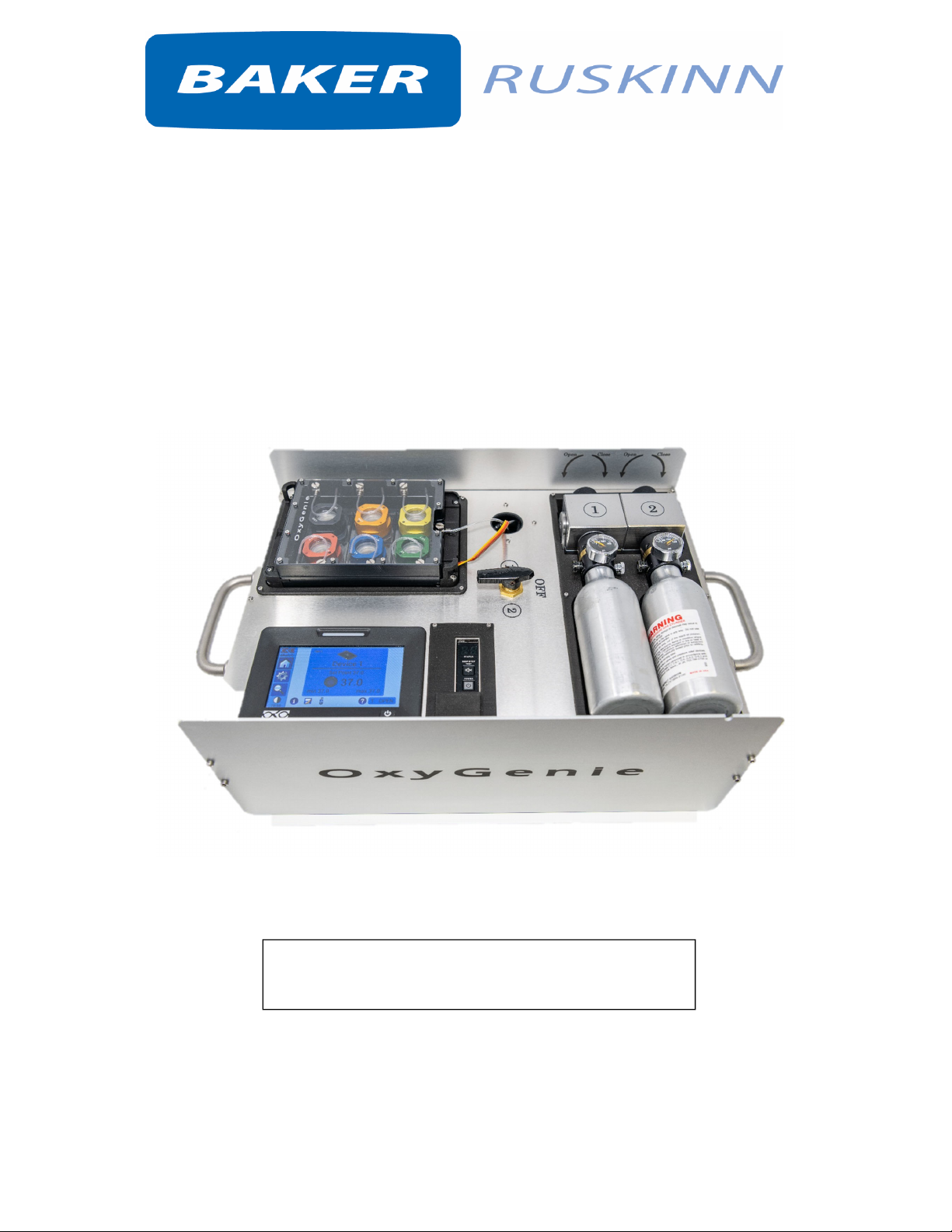
Baker Ruskinn OxyGenie User manual

AffixSerialNumberStickerHere
User Manual UM-049
OxyGenie™
OxyGenie™

i
Unit8&9/YorkPark/Bridgend,UnitedKingdom/CF313TB
+44(0)1656645688/Fax:+44(0)1656667966/sales@ruskinn.com/
www.bakerruskinn.com
CONTENTS
TABLEOFFIGURES..................................................................................................................................II
TABLEOFTABLES....................................................................................................................................II
INTRODUCTION.......................................................................................................................................3
SAFETYINSTRUCTIONS............................................................................................................................4
REGULATORYCOMPLIANCE....................................................................................................................6
EUROPEANREGION.............................................................................................................................6
SYMBOLS.............................................................................................................................................7
TRANSPORTANDSTORAGE....................................................................................................................8
ENVIRONMENTALOPERATINGCONDITIONS..........................................................................................8
OXYGENIE™OVERVIEW..........................................................................................................................9
BACKGROUND.....................................................................................................................................9
HOWTOUSEOXYGENIE™.....................................................................................................................10
POWERSUPPLY.....................................................................................................................................11
GASBOTTLEFITTING.............................................................................................................................12
GASBOTTLES.........................................................................................................................................14
GASBOTTLEASSEMBLY.........................................................................................................................15
CHANGINGTHEGASBOTTLE................................................................................................................15
GASCYLINDERADAPTER.......................................................................................................................16
1‐WELLASSEMBLYANDCELLCULTIVATION.........................................................................................1 7
COVER...................................................................................................................................................18
ADDING1‐WELLASSEMBLYTOSYSTEM...............................................................................................19
HEATPLATEBYOKOLAB........................................................................................................................21
HOMEPAGE.......................................................................................................................................23
STATUSLEDCOLOURS.......................................................................................................................24
TOSETTEMPERATURE......................................................................................................................24
SETTINGS...........................................................................................................................................24
SETTINGS;DEVICES...........................................................................................................................25
SETTINGS;CALIBRATIONS.................................................................................................................26
SETTINGS;DATALOGGING................................................................................................................32
SETTINGS;ALARMS...........................................................................................................................35
SETTINGS;DISPLAY............................................................................................................................36
SETTINGS;PASSWORD......................................................................................................................38
SETTINGS;SUMMARY.......................................................................................................................39

ii
Unit8&9/YorkPark/Bridgend,UnitedKingdom/CF313TB
+44(0)1656645688/Fax:+44(0)1656667966/sales@ruskinn.com/
www.bakerruskinn.com
CHECKLIST.............................................................................................................................................40
WARRANTYINFORMATION...................................................................................................................41
DISPOSALINFORMATION......................................................................................................................42
CONTACTDETAILS.................................................................................................................................43
TABLEOFFIGURES
Figure1‐PowerSupply........................................................................................................................11
Figure2‐Powerdisplaymessages.......................................................................................................11
Figure3–Fillingstationtogascylinder................................................................................................13
Figure4‐Fillingsttiontobottle............................................................................................................13
Figure5‐Controlknobopening...........................................................................................................13
Figure6‐Gasbottleassembly..............................................................................................................15
Figure7–Changingthegasbottle.......................................................................................................15
Figure8‐Gascylinderadapter.............................................................................................................16
Figure9‐Gascylinderadaptertoregulator.........................................................................................16
TABLEOFTABLES
Table1:ListofSymbols...........................................................................................................................7

3
INTRODUCTION
PleasereadthismanualcarefullybeforeusingtheOxyGenie™andfamiliariseyourselfwithallaspectsof
using the product. The Baker Company (Baker) or Ruskinn Technology Ltd (Ruskinn) does not accept
responsibilityforaccidentstopersonnelordamagetotheOxyGenie™resultingfromincorrectuse.
ManyuniquefeaturesoftheOxyGenie™arecoveredindetailinthismanual.Itisrecommendedthatthe
user be fully conversant with the instruction and procedures, and that the operator familiarises
themselveswithallaspectsandfunctionsofthesystembeforeitiscommissionedtomaintainoptimum
performance.

4
SAFETYINSTRUCTIONS
Bakerand/orRuskinndonottakeanyresponsibilityfordamagescausedbyusingtheequipmentforother
purposesthandescribedinthisusermanual.
ThisisaClassAproduct(forindustrialenvironments).Inaresidentialenvironment,itmaycauseradio
interference.Ifradiointerferenceoccurs,theusermayberequiredtotakeappropriatemeasures.
Thisdevicecontainshighpressuregases.
Ifthereisgapbetweengasbottleandregulatordonotuseorfillthisbottle.Placethisbottleonground
onanisolatedsafeplacetoletthegasbottletofullydegas.
Thisdevicecontainselectronics.
Thisdevicecontainsheatingelements.
Donotchangeheatingdevicetypesettingsfromheatplatecontroller.
Donotreplaceanypartsofthedeviceoritscomponents.
Thisdeviceisintendedtouseinresearchonly.
Deviceshouldbeonlyusedbytechnicallyqualifiedperson.
Devicemustbeusedaccordingtomanualinstructions,ifusagedeviatesfromtheinstructionsthe
performancecanbeharmed.
Ifanydamagesappear,thedeviceshouldnotbeused.
Ifunusualperformanceoccurs,suchasdeformation,discoloration,abnormalsoundorsmell,orabnormal
heatingstopusingthedeviceandcontacttheprovider.
Ifanyliquidleaksfrominteriorbatterydonottouchthefluid.
Alwaystransportthedevicewithcareanddonotdroporapplyanyshockorvibrationstothedevice.
Alwaysplacedeviceonrobustandstablesurface.
Somepartsofthedevicecanreachhightemperatures,thusdonottouchtheseparts.
Avoidrapidtemperaturechanges,moisture,moistcondensation,airdrafts,directsunlight,temperature
wayaboveorbelowroomtemperature,excessiveinductionnoise,staticelectricityandmagneticfields,in
thedevicesurroundingsanddirectcontact.
Donotusethisdeviceinsamesurroundingswithflammableorexplosivegases.
Donotdisassembleanypartsfromdevice.
Donotuseharshsolventstocleantheinstrument,thismaycausedisruptionofdevice.
Donotinducethedeviceforhighvoltagesanduseonlyelectriccordsequippedwiththedevice.
Donotinducephysicalweartocables,tubesoranyparts.
Avoiddustparticlesneargasbottleconnections.
Useonlythepowersupplyprovidedwithdevice.
Alwaysconnectpowersupplycablefirsttothedevicebeforeconnectingittoapowersocket.
Donotconnectpowersupplycableorturnonthedeviceifanycablesaredamaged.
Connectthedeviceonlytogroundedmainpowerdistributionnetwork.
Whenhandlinggasbottlesbeextracareful.
Alwayscheckyourgasbottlesbeforeusing.
Donotuseorfillgasbottlesthataredamaged.
Donotfillbottleswithgasmixturescontainingoxygenmorethan21%atanycircumstances.
UnderNOCIRCUMSTANCESshouldthesystembefilledwithpureoxygen.Oxygenwillignitecausinginjury
ordeath.
Donotletanydirt,wateroroilstobecomeincontactwithgasbottleregulators.

5
CAUTION: Asphyxiation Risk
The OxyGenie™ uses Nitrogen (N2) and Carbon Dioxide (CO2)aspartofnormalusewiththevolume
releasedexternallyisinconsequential.Intheeventofaleakormalfunctionthisgasreleasemaybecome
excessive.DONOTOPERATEthisunitinaSMALLENCLOSUREsuchasasmallroomorwalk‐incloset.An
accidentalreleaseofNitrogenorCarbonDioxidecouldcreatean asphyxiating atmosphere in a small
space.
If the equipment is not use in a manor specified by the manufacture, the protection provided by the
equipmentmaybeimpaired.
Failuretoadheretothesesafetyinstructionscouldcauseseriousinjuryandwillinvalidatetheworkstation
warranty.RuskinnTechnologyLimitedacceptsnoresponsibilityforanyaccident,injuryorlosscausedby
unsafeoperationoftheworkstation.

6
REGULATORYCOMPLIANCE
EuropeanRegion
ThisproductcomplieswiththeessentialEEArequirementsforElectrical Safety and Electromagnetic
compatibilityasset out inthe EMCDirective 2014/30/EU, the LowVoltageDirective2014/35/EUand
hazardoussubstances(RoHS)Directive2011/65/EUhasbeentestedandfoundtocomplyinfull.
FordetailsonstandardstestedrefertotheDoCCertificate.
WEEE:
This equipment must be disposed of in accordance with the WastefromElectricalandElectronic
Equipment(WEEE)Directive
Thisproductmustnotbetreatedashouseholdwaste.Instead,itshallbehandedovertoanappropriate
collectionpointfortherecyclingofelectricalandelectronicequipment.
Ifindoubt,pleasereturnthisequipmenttoRuskinnTechnologyLtdwhowillcorrectlydisposeofitfor
you.WestronglyrecommendthatthisproductisreturnedtoRUSKINNTECHNOLOGYLIMITEDattheend
ofitsusefullife.

7
Symbols
BeforeusingtheOxyGenie™,pleaseensurethatyouarefamiliarwiththesymbols.
Symbol Meaning
Refertousermanual.
~
Alternatingcurrent
OOff
IOn
FunctionalEarthConnection
ProtectiveEarthConnection
This product complies with the essential EEA requirements for Electrical Safety
andElectromagnetic compatibilityassetoutintheEMCdirective2004/108/EC
andtheLowVoltageDirective2006/95/EC
Caution, do not remove covers. No end user serviceable parts behind covers.
Pleaserefertothismanualinallcaseswherethissymbolappears,inordertofind
outthenatureofthePotentialHazardandactionstobetakeninordertoavoid
theHazard.
Warning,thisequipmentcontainshighvoltagecircuitry.
Containsmaterialorsubstancesthatmaybehazardoustohumanhealth.Please
refertoyourlocalbiohazardousmaterialhandlingprocedureforfurtheradviceon
thehandlinganddisposaloftheseitems.
OxyGenie™ contains hazardous components and must not be disposed of at a
household waste site. Instead it should be taken to the appropriate collection
pointfortherecyclingofelectricalandelectronicequipment.
USBsocket
07/2019
Dateofmanufactureinformat
MM/YYYY
Table1:ListofSymbols

8
TRANSPORTANDSTORAGE
Whennotinuse,theOxyGenie™mustonlybestoredwithinatemperatureofbetween0°Cand30°C
Storageoutsideofthisrangemaycausedamage.
ENVIRONMENTALOPERATINGCONDITIONS
TheOxyGenie™shouldonlybeoperatedunderthefollowingenvironmentalconditions:
Temperature–Between15⁰Cand30⁰C
Humidity–Betweenambientand90%RH,Non‐Condensing
TheOxyGenie™mustbelocatedinawell‐ventilatedarea.

9
OXYGENIE™OVERVIEW
Background
OxyGenie™isamini‐incubatorforcellculturestudies.Gasbottlescontainingdifferentgasmixtureswillallowyou
tocontrolgasenvironmentinsidethecellculturestructures.Withthisdevice,oxygenlevelscanbecontrolledwhile
pHandtemperatureparametersaremaintainedstable.
OxyGenie™:
1. Heatplate
2. 6‐wellflowdivider
3. Open/closebottlevalve(separateforeach
gasbottle)
4. Gaschannelselectionvalve
5. Gasbottles
6. Heatplatecontrollerandheatplateswitch
button
7. Devicepowerswitch/batteryandpower
display
8. Cover
9. LidLock
10. Lid
11. CoverLock
12. 1‐wellstructurewithglasssubstrate
Othercomponentsprovidedwithdevice:
‐ Powercord
‐ Temperaturesensor(k‐typetemperaturesensor)
‐ Gascylinderadapter.Thisisaplugwithpush‐inconnectorforgassupplyfromthelargecylinders
(additionalcomponentsusermustpurchase:4mm(5/32”)PU‐tubingandlargegascylinders)
6.
4.
7.
5.
3. 8.
9.
10.
12.
1.
2.
11.
Allcomponentscanbewipedwith70%EtOH.
Notethatdevicechargesbatteryonlywhenturnedon.

10
HOWTOUSEOXYGENIE™
Check/switchgas
bottles
•Checkgasvolume
Preparedevice
•Selectgasbottlefrombottle
selectionvalveandopenthe
bottlevalve
•Letsystemequilibrate
Checkthedevice
•Checkthevalves
•Checktheheatplate
•Checkthatthedeviceis
charging
Addstructuresto
6‐wellflowdivider
•Checkthecovers
•Connectflowdivider
gastubestocovers
Preparecells
•Assemble1‐well
structure
componentsandadd
cover

11
POWERSUPPLY
Pressgreyswitchbuttonfor3secondstoturnonthe
device.(Inpicture)
Pressheatplatecontrollerswitchbuttontoturnon
heatplate.(Seeheatplatecontroller)
Beeptestisdisabledinthisdevice.
Toshutdownthewholedevice,switchoffheatplate
from the controller switch button and press grey
switchbuttonfor3seconds.
Figure1:PowerSupply
Powerdisplaymessages
Poweroff
Device
performs quick
self‐diagnosis.
Low battery,
put device on
charge.
Poweron.
Dot on bottom
right indicates
thatdeviceison
charge.
Device
operates on
battery.
Battery out of
power.
Figure2:Powerdisplaymessages
Forotherpermanentmessagesondisplay,pleasecontactprovider.
Notethatdevicechargesbatteryonlywhenturnedon.
Batterylifeofthisdeviceisabout2hours.
Useonlythepowersupplyprovidedwithdevice.

12
GASBOTTLEFITTING
Donotattachanycomponentsorfillgasbottlesuntilyouhavereadandunderstoodalloftheseinstructions.
Fillstationmustbepurchasedseparately.Withoutfillingstationbottlesarenotpossibletobefilled.
Fillinggascylindersmustbepurchasedfromlocalgassupplier.Asktherightfittingforthecylinderthreads
fromyourlocalgassupplier. Threads in thefillingstationis ¼” NPT male threads. Makesurethatthe
fittingiswithcorrectthreadsforthecylinder.Cylinderthreadsaredifferentindifferentcountries.Ask
safetyinstructionsfromlocalgassupplier.
Fillinggascylindermustbeproperlysecuredfromincliningorfallingbeforeattachingfillingstationtoit.
Confirmthatfittingiscompatiblewithyourfillstation.
Alwaysweareyeprotectionandheavygloveswhenhandlinghighpressuregases.
Alwayspointeveryairsystemsinsafedirectionawayfromyourselfandotherswhiledegassingand
fillingthegasbottles.
Donotfillbottleswithgasmixturescontainingoxygenmorethan21%atanycircumstances.
Donotusecompressedairorotherparticleand/ormoisturecontaminated gasses at any
circumstances.
Alwayscheckthatallyourcomponentsareunharmedwithoutanyvisiblefracturesandflaws(seepage
10)
Donotuseexcessiveforcewhenhandlinganyofcomponentsorfillingstations.
Donotfillthebottlesmorethan1500PSIatanycircumstances.
Notethatgasbottlescannotbefilledwithmorethanpressurecontainedinyourfillinggascylinder.
Alwaysmarkthegascompositioninyourgasbottles.

13
Tightenthefillingstationtogascylinder.Makesureitisproperly
attached.
MakesurethatfillingstationCONTROLKNOBisturnedalltheway
counter‐clockwise.Donotuseforceto operatetheknob.Open
gascylinderslowlyandletthepressureflowtothefillingstation.
BULKgaugeshowspressureleftinfillinggascylinder.
OUTPUTgaugeshowpressurethatwillbedispensedtoyourgas
bottle.
Dispensed pressure can be adjusted by the output pressure
ADJUSTMENTSCREW.Pressurecanbesetbyturningthescrew
with3/16inchAllenkey.Byturningclockwisetheoutputpressurewillriseandcounter‐clockwiseitwill
decrease.Afteryouhavesetthedesiredpressure(maximum1500psi),letairoutbyturningcontrolknob
andyouwillnoticethattheoutputpressurechangesfromsetvalue.Repeatthispressureadjustmentand
air release cycle until the pressure reaches desired value after theair is released. This venting step is
importantespeciallywhenvaluesaresettoloverrange.ChecktheunitALWAYSbeforeuse,becausethe
valuescanchangeovertime.
Makesureallthebottleattachmentcomponentsareunharmed
andairflowfromventingholeisnotblocked.Attachthebottleto
the filling station by pushing the bottle attachment connector
backwards.Afterbottleisproperlyattachedandlockedonthe
connector,theconnectorshouldslidebacktoitsplaceandmake
clicksound.
Turnandholdthecontrolknobclockwiseuntilgasstarttoflowto
bottle.Afterthis,turnthecontrolknob¼further.Waitfor
pressure flowing to stop and let the pressure settle for at least
30seconds.Followthegasbottlepressureindicatorthatitwon’t
exceed1500psi.
Whenthebottleisfullturnthecontrolknobcounter‐clockwiseto
ventthefillingstationfullyempty.
Detachbottlefromregulatorandclosegascylinder.
WARNING Always check that OUTPUT pressure does not
exceed1500PSIatanycircumstances!
WARNINGIfgasbottleisnotdetachingeasilypressuremaystill
occupy components! Empty the filling station properly by
turningthecontrolknob.
WARNING!Alwaysoperateoncompletelyemptyfillingstation.
Figure3–Fillingstationtogascylinder
Figure4‐Fillingsttiontobottle
Figure5‐Controlknobopening

14
GASBOTTLES
Compartments:
1. Bottleregulator
2. Pressuregauge
3. Gasbottle
4. Plasticregulatorcap
5. Burstdisk(3k)
6. Fillingnibble
7. Rotationaladjustingcollar
8. Burstdisk(1.8k)
WARNING!
If there is gap between
gas bottle and regulator,
donotuseorfillthis
bottle.Placethisbottleon
groundonanisolatedsafe
placetoletitfullydegas
andcontact
p
rovider.
4.
1.
3.
2. 5.
6.
7.
8.
WARNINGhighpressure
Donotuseorfillthebottleifanyfracturesorflawsarevisible.
Donotapplyheat.
Donotuseexcessiveforcewhenhandlinggasbottles.
Gasbottlemustbechangedbeforepressuredisplayreachzero.
Alwayscheckgasbottleandthatitcontainsasuitablegascomposition.
Alwayscheckthatyouhaveenoughgastoperformyourexperiments.
Alwayscovertheheadoftheregulatorwithagasbottleregulatorcap,donotletanydirt,wateror
oilstobecomeincontactwithgasbottleregulators.

15
GASBOTTLEASSEMBLY
1. Tightengentlygasbottlestoplacesindicatedbynumbers1and2.
Do not use excessive force to tighten the bottles.
2. Openonlyonebottlevalve(#2inthepicture)byturninggentlyall
thewaytotheleft.Do not use excessive force.
3. Turn the gas channel selection valve to correct position. Pointy
headindicateswhichbottlevalveisopen.
Notethatonlyonebottlecanbeopenatatime.
CHANGINGTHEGASBOTTLE
1. Closethebottlevalve(redarrow)byturningthevalvegentlyallthewaytotheright.Wait1
minuteforpressuretosettle.Opentheotherbottlevalve(greenarrow)byturningthevalve
gentlyallthewaytotheleft.Do not use excessive force.
2. Turnthegaschannelselectionvalvetoposition2forcontinuous gas flow. Pointy head
indicateswhichvalveisopen.
3. Removetheemptybottleandreplaceitwithanewbottle.Do not use excessive force to
tighten the bottle.
Figure7–Changingthegasbottle
1.
2.
3.
1. 2. 3.
Figure6‐Gasbottleassembly

16
GASCYLINDERADAPTER
Gas cylinder adapter allows gas to be fed from larger gas cylinders, thus allowing prolonged
experiment time without changing gas bottles. Attach the adapter same way as gas bottles are
attachedtothedevice.
Attach4 mm (5/32“)polyurethane tubing betweenadapterandgas cylinderregulator. Attach gas
cylinderadaptertodeviceandadjustgascylinderregulatorto1bar.Makesurethatbottlevalveis
openandgaschannelisselectedcorrectly.
Note!TheOxyGenie™bottlevalvecannotclosethegasflow.Gasflowmustbeclosedfromthegas
cylinderregulator.
Usermustpurchasetubing,cylinderregulatorsandgascylindersfromotherproviders.
Figure8‐Gascylinderadapter
Figure9‐Gascylinderadaptertoregulator

17
1‐WELLASSEMBLYANDCELLCULTIVATION
1‐wellstructurebottomcanbecoatedbeforeculturingcells.Cellscanbe
culturedinthesestructuresbyfollowingregularprotocols.
HowtopreparestructurestoOxyGenie™:
1. Addincellculturemediumandothernecessarysubstances.
!Optimalvolumeforsubstancesis1ml.
2. Placethelidoverthe1‐wellstructure.
!Makesureitfitscorrectly.
3. Placethelidlockaroundthe1‐wellstructureandthelid.
!Makesureitgripsthelidtightlyandcorrectlyaroundthestructure.
4. Whenallthesecomponentsareplacedcorrectly,thecovercanbe
addedtoencasethewhole1‐wellstructure.
Alwaysusenewandsterile1‐wellstructures.
1‐wellstructures,lidsandlidlocks,coversandcoverlocksarecompatiblewithautoclave,EtOHand
shorttermUVsterilization.

18
COVER
The cover encloses the 1‐well structure and maintains correct gas composition in cell culture
environment.
Howtoplacethecover:
1. Place cover lock on the groove of 1‐well structure so that little
shoulderisupwards
2. Place the cover on top of the 1‐well structure. The cover lock will
allowthecoversqueezetightlyaroundsiliconestructure.
3. Makesurethecoverispushedtothebottom.
1‐wellstructuresarenowreadytobeassembledtoOxyGenie™.
Tip:Usevery thinlayerofsiliconegreasein
the lip of the cover [1]. That will help the
assembly of the cover and ensure better
sealingofthecover.
Do notspreadthegreasetotheoutlettube
(whitetube[2])orthemightbepartlyorfully
blocked.Alwaysremembertochecktheout
flowfromthechamber(checktheTipinthe
nextpage).
Ifcoversarenotadjustedalltowaytothebottom,theymayleakand
affecttothegasconcentrationsinsidethecellculture.
1.
2.

19
ADDING1‐WELLASSEMBLYTOSYSTEM
Ensurethatthegasbottlesareopenandgasisflowing.
Tip: Tubes coming from flow divider can be submerged in small
amountofEtOH(e.g.insmallcentrifugetube)andcheckthatbubbles
comeouttoensuregasflow.
Add1‐wellstructuresto6‐wellflowdividerasindicatedinpictures.
ConnecttheflowdividertubestothecoverinletmarkedwithINandmakesurethatitisproperly
attachedsothatmetaltubingishidentirely.
Tip:FewmicrolitersofwaterorEtOHcanbealsopipettedtotheOUTofcoversandensurethatit
bubblestoensuregasflow.
Ifflowdividertubeisnotused,attachittothecoreoftheflowdivider.
Thiswillkeepoutletcleanandpreventinggasflowthatincreasethelife
timeofthegassupplyfromthebottles.
Beforeadding1‐wellassemblytotheOxyGenie™system,makesure that you have a correct gas
compositionandenoughgasinthebottles.Alsocheckthatbottles/gascylinderadapterareproperly
assembled.
Confirmthatthecoversareassembledcorrectly.
6‐wellflowdividercanbewipedwith70%EtOH.
Table of contents
Other Baker Ruskinn Laboratory Equipment manuals