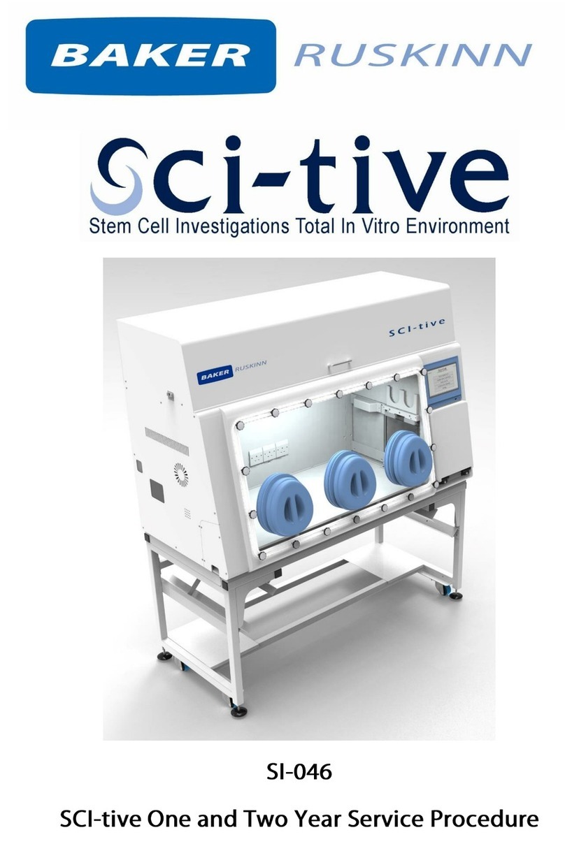
Baker Ruskinn Concept-M User manual

Affix Serial Number Sticker Here
User Manual UM-039
Concept-M
Anaerobic and Microaerophilic
Workstation
Concept-M 400 / Concept-M 500

i
Unit 8&9 / York Park / Bridgend, United Kingdom / CF31 3TB
+44 (0) 1656 645688 / Fax: +44 (0) 1656 667966 / sales@ruskinn.com /
www.bakerruskinn.com
CONTENTS
TABLE OF FIGURES .........................................................................................................III
TABLE OF SCREEN IMAGES............................................................................................. IV
TABLE OF SCREEN ICONS ............................................................................................... IV
TABLE OF TABLES ........................................................................................................... IV
INTRODUCTION ................................................................................................................ 1
SAFETY INSTRUCTIONS ................................................................................................... 2
REGULATORY COMPLIANCE ............................................................................................. 3
EUROPEAN REGION...................................................................................................... 3
NORTH AMERICAN REGION .......................................................................................... 4
PRECAUTIONS .............................................................................................................. 4
SYMBOLS ..................................................................................................................... 5
TRANSPORT AND STORAGE ............................................................................................. 6
LOCATION AND HANDLING OF THE CONCEPT WORKSTATION........................................... 6
ENVIRONMENTAL OPERATING CONDITIONS .................................................................... 6
SERVICE REQUIREMENTS................................................................................................ 7
ELECTRICAL SUPPLY REQUIREMENTS.......................................................................... 7
GAS SUPPLY REQUIREMENTS ...................................................................................... 8
CONCEPT OVERVIEW........................................................................................................ 9
FRONT VIEW ................................................................................................................. 9
FRONT INTERIOR VIEWS ............................................................................................. 10
LEFT SIDE VIEW .......................................................................................................... 11
RIGHT SIDE VIEW........................................................................................................ 12
REAR VIEW ................................................................................................................. 13
USING THE WORKSTATION............................................................................................. 14
USING THE INTERLOCK .............................................................................................. 14
INTERLOCK OVERVIEW ............................................................................................... 14
OPERATING THE INTERLOCK OUTER DOOR................................................................. 14
OPERATING THE INTERLOCK INNER DOOR ................................................................. 15
TRANSFERRING MATERIAL INTO THE WORKSTATION CHAMBER VIA THE INTERLOCK 15
REMOVING MATERIAL FROM THE WORKSTATION CHAMBER VIA THE INTERLOCK...... 17
HAND ACCESS TO THE MAIN CHAMBER ..................................................................... 18
VACUUM OPERATION.................................................................................................. 19

ii
Unit 8&9 / York Park / Bridgend, United Kingdom / CF31 3TB
+44 (0) 1656 645688 / Fax: +44 (0) 1656 667966 / sales@ruskinn.com /
www.bakerruskinn.com
WORKSTATION ENTRY ................................................................................................ 21
WORKSTATION EXIT.................................................................................................... 23
HUMIDITY CONTROL ................................................................................................... 24
SCREENS....................................................................................................................... 26
MAIN SCREEN ............................................................................................................ 26
INITIAL SETTINGS SCREEN......................................................................................... 27
ENVIRONMENT CONTROL ........................................................................................... 29
DATA LOG ................................................................................................................... 30
UTILITIES.................................................................................................................... 31
OXYGEN SENSOR CALIBRATION ................................................................................. 32
HELP / SETTINGS........................................................................................................ 33
WARNINGS ................................................................................................................. 34
USB TREND LOG............................................................................................................. 38
CLEANING AND SERVICE REQUIREMENTS..................................................................... 39
SERVICE AND CLEANING OVERVIEW........................................................................... 39
CLEANING PROCEDURE –DURING AND AFTER EACH USE.......................................... 40
CLEANING PROCEDURE –DEEP CLEAN WITH FRONT SCREENS REMOVED ................ 41
1 YEAR SERVICE ......................................................................................................... 44
TROUBLESHOOTING....................................................................................................... 46
THE WORKSTATION WILL NOT SWITCH ON.................................................................. 46
THE CIRCUIT BREAKER TRIPS..................................................................................... 46
LOW GAS PRESSURE .................................................................................................. 46
EXCESSIVE GAS USAGE .............................................................................................. 47
INTERNAL EQUIPMENT NOT POWERING UP................................................................ 47
THE WORKSTATION IS ONLY PARTIALLY OPERATIONAL .............................................. 47
WARRANTY INFORMATION ............................................................................................. 48
DISPOSAL INFORMATION............................................................................................... 49
CONTACT DETAILS ......................................................................................................... 50

iii
Unit 8&9 / York Park / Bridgend, United Kingdom / CF31 3TB
+44 (0) 1656 645688 / Fax: +44 (0) 1656 667966 / sales@ruskinn.com /
www.bakerruskinn.com
TABLE OF FIGURES
Figure 1: Concept Rear Connections ................................................................................ 7
Figure 2: Gas Connection Graphic .................................................................................... 8
Figure 3: Standard Concept Workstation with SPES Option.............................................. 9
Figure 4: Large Concept Workstation ............................................................................... 9
Figure 5: Right Side Internal View................................................................................... 10
Figure 6: Left Side Internal View..................................................................................... 10
Figure 7: Left Side End Panel with Ultrasonic Humidity Option ...................................... 11
Figure 8: Right Side End Panel ....................................................................................... 12
Figure 9: Rear End Panel and Supply Connections ......................................................... 13
Figure 10: Gas and Electrical Connections ..................................................................... 13
Figure 11: Ezee -Sleeves ................................................................................................ 18
Figure 12: Compressed Ezee-Sleeve for Entry................................................................ 19
Figure 13: Arm inserted into Ezee-Sleeve (Shown with and without Ezee-Sleeve).......... 19
Figure 14: Foot pedals for right and left glove ports ....................................................... 20
Figure 15: Ezee-Sleeve before vacuum........................................................................... 20
Figure 16: Ezee-Sleeve after vacuum ............................................................................. 20
Figure 17: Glove port cap ............................................................................................... 21
Figure 18: Glove port cap stowage and locator ............................................................... 21
Figure 19: Glove port cap storage location inside workstation........................................ 22
Figure 20: Glove port cap ............................................................................................... 23
Figure 21: Glove Port Locator ......................................................................................... 23
Figure 22: Aquasorb Sachets - Empty and Charged........................................................ 24
Figure 23: Aquasorb Sachet in Workstation.................................................................... 24
Figure 24: Condensate Plate .......................................................................................... 25
Figure 25: Condensate Output and Tray ......................................................................... 25
Figure 26: Front Screen Pneumatic Connector Disconnection........................................ 41
Figure 27: Ceiling Panel Thumb Screws.......................................................................... 44
Figure 28: Ceiling Panel Handle and Grab Catch............................................................. 44
Figure 29: Large Detox Sachet........................................................................................ 45
Figure 30: Large Catalyst Sachets.................................................................................. 45
Figure 31: Gloveport Sleeves.......................................................................................... 45

iv
Unit 8&9 / York Park / Bridgend, United Kingdom / CF31 3TB
+44 (0) 1656 645688 / Fax: +44 (0) 1656 667966 / sales@ruskinn.com /
www.bakerruskinn.com
TABLE OF SCREEN IMAGES
Screen 1: Interlock Purge Options.................................................................................. 16
Screen 2: Interlock Purge Timer ..................................................................................... 16
Screen 3: Main Menu ..................................................................................................... 26
Screen 4: Initial Settings Screen with Ultrasonic Humidity Option ................................. 27
Screen 5: Oxygen Level Set-point Pop-up ...................................................................... 27
Screen 6: 0% Oxygen Settings Screen with Aquasorb Humidity Option .......................... 28
Screen 7: Environment Control Overview........................................................................ 29
Screen 8: Exit Gas Control Warning ................................................................................ 29
Screen 9: Trend Log ....................................................................................................... 30
Screen 10: Utilities Menu ............................................................................................... 31
Screen 11: Oxygen Sensor Calibration............................................................................ 32
Screen 12: Help / Settings Menu.................................................................................... 33
Screen 13: Temperature Alarm Screen........................................................................... 34
Screen 14: USB Memory Warning Screen ....................................................................... 35
Screen 15: Gas Mix Time Limit Warning Screen .............................................................. 36
Screen 16: Input Gas Pressure Alarm ............................................................................. 37
TABLE OF SCREEN ICONS
Icon 1: Interlock Outer Door ........................................................................................... 14
Icon 2: Internal Lights Control ........................................................................................ 31
Icon 3: Front Screen Release.......................................................................................... 41
TABLE OF TABLES
Table 1: List of Symbols ................................................................................................... 5
Table 2: Electrical Service Requirements......................................................................... 7
Table 3: Fuse Ratings....................................................................................................... 8
Table 4: Standard Gases .................................................................................................. 8
Table 5: Additional gases for specific operating modes.................................................... 8
Table 6: Settings screen column functions..................................................................... 27
Table 7: Audible Alarm Sounds....................................................................................... 37
Table 8: Trend Log Data Fields ....................................................................................... 38
Table 8: Cleaning and Service Details............................................................................. 39

Page 1of 50
INTRODUCTION
Please read this manual carefully before using the Concept and familiarise yourself with
all aspects of using the workstation. The Baker Company (Baker) or Ruskinn Technology
Ltd (Ruskinn) does not accept responsibility for accidents to personnel or damage to the
Concept workstation resulting from incorrect use.
The Concept has been specifically designed and developed to meet the requirements of
all laboratories. The unit is ergonomically laid out to ensure maximum operator comfort
and optimization of space for media preparation, manipulation, and analysis. Concept is
designed to give optimum ‘in-vitro’ conditions for cell culture in a simple and easily
controlled manner.
The system has built in gas control with Oxygen and Carbon Dioxide sensors to enable
constant monitoring of the atmosphere. Hypoxic conditions are created using Nitrogen
(N2), Carbon Dioxide (CO2) and Compressed Air (O2) (or 25% Oxygen in Nitrogen) to achieve
the desired atmosphere. The user can select the Oxygen concentration from 0.1% to
20.9%, and Carbon Dioxide concentrations from 0.1% to 30.0%.
A Heater system maintains the temperature within the workstation between ambient +5°C
to 45°C, which is set by the user. The cooling accessory for the workstation will achieve an
unloaded temperature of 15°C or less which is set by the user.
Optional humidity generation system allows the maintenance of Relative Humidity levels
from ambient to +85% RH @ 37°C which is user settable. The generation of humidity is
either through nebulisation which promotes evaporation from a body of water by breaking
the surface tension or through steam generation.
Many unique features of the Concept workstation are covered in detail in this manual. It is
recommended that the user be fully conversant with the instruction and procedures, and
that the operator familiarises themselves with all aspects and functions of the system
before it is commissions to maintain optimum performance.

Page 2of 50
SAFETY INSTRUCTIONS
Baker and/or Ruskinn do not take any responsibility for damages caused by using the
equipment for other purposes than described in this user manual.
The mains appliance coupler and plug are the AC mains supply isolation device and must be
easily accessible when installed.
In case of emergency disconnect the Concept from the AC Mains Outlet.
Ensure that the connecting cable is not squeezed or bent when the unit is being installed or
moved.
All installation work and adjustments to the unit must be carried out by qualified personnel.
Work performed by persons with insufficient technical knowledge may adversely affect the
performance of the unit or cause physical injury or damage to the equipment.
All servicing and repairs must be carried out by a qualified customer service engineer. Only
genuine spare parts must be used.
In case of damage to the Invivo disconnect the workstation from the mains outlet and contact
your local distributor.
All covers and lids must only to be removed by a qualified service engineer.
Nothing should be placed on the top of the workstation.
A power cord supplied with the workstation and should be used to connect to the mains outlet.
If a replacement is required it must be adequately rated for the application.
All cables and pipes should be routed to ensure that they do not pose a trip hazard.
Mains supply Voltage fluctuation must not exceed ±10% of the nominal Voltage.
Gas regulators must be used for each gas supply. A 2 stage regulator is recommended with a
maximum supply pressure of 4 Bar. Over pressure could damage the workstation.
Only the gases specified in this user manual may be used.
All gas bottles must be adequately secured before connection to the workstation.
The maximum power rating of the internal sockets must not be exceeded.
The end user is responsible for all materials and equipment places inside the workstation.
Before connecting any equipment to the internal mains sockets ensure that the equipment has
or is connected to a protective earth. If in doubt please contact the equipment manufacturer.
The workstation must not be operated at an ambient temperature over 30°C.
The cooling fan covers and cooling vents must not be covered or blocked.
The weight limit for the workstation internal floor is 30kg and must be evenly distributed.
The weight limit for the interlock tray is 5kg and must be evenly distributed.
There should be no naked flames close to the workstation.
The use of radioactive materials if strictly prohibited.
CAUTION: Asphyxiation Risk
The Concept uses Nitrogen (N2) and Carbon Dioxide (CO2) as part of normal use with the
volume released externally is inconsequential. In the event of a leak or malfunction this
gas release may become excessive. DO NOT OPERATE this unit in a SMALL ENCLOSURE
such as a small room or walk-in closet. An accidental release of Nitrogen or Carbon Dioxide
could create an asphyxiating atmosphere in a small space.
If the equipment is not use in a manor specified by the manufacture, the protection
provided by the equipment may be impaired.
Failure to adhere to these safety instructions could cause serious injury and will invalidate
the workstation warranty. Ruskinn technology limited accepts no responsibility for any
accident, injury or loss caused by unsafe operation of the workstation.

Page 3of 50
REGULATORY COMPLIANCE
European Region
This product complies with the essential EEA requirements for Electrical Safety and
Electromagnetic compatibility as set out in the EMC Directive 2014/30/EU, the Low
Voltage Directive 2014/35/EU and hazardous substances (RoHS) Directive 2011/65/EU has
been tested and found to comply in full.
For details on standards tested refer to the DoC Certificate
WEEE:
This equipment must be disposed of in accordance with the Waste from Electrical and
Electronic Equipment (WEEE) Directive
This product must not be treated as household waste. Instead, it shall be handed over to
an appropriate collection point for the recycling of electrical and electronic equipment.
If in doubt, please return this equipment to Ruskinn Technology Ltd who will correctly
dispose of it for you. We strongly recommend that this product is returned to RTL at the
end of its useful life.

Page 4of 50
North American Region
This product is UL 61010-1 Listed, and CSA C22.2 No. 61010-1 under file number E113911.
This equipment has been tested and found to comply with the limits for a Class A digital
device, pursuant to part 15 of the FCC Rules. These limits are designed to provide
reasonable protection against harmful interference when the equipment is operated in a
commercial environment. This equipment generates, uses, and can radiate radio
frequency energy and, if not installed and used in accordance with the instruction manual,
may cause harmful interference to radio communications. Operation of this equipment in
a residential area is likely to cause harmful interference in which case the user will be
required to correct the interference at his own expense.
Precautions
The Concept has been tested and approved to EN61010-1, 61326-1, and 61326-2-6. This
means that the Concept meets or exceeds the requirements for General and IVD electrical
Laboratory equipment in terms of its levels of emitted electromagnetic (EM) radiation and
its susceptibility to electromagnetic radiation from other devices. It should be noted that
the Concept may be affected by high levels of stray EM radiation from other electronic
devices (even those which comply with relevant CISPR emission standards) that are being
used in close proximity to it.
WARNING: This system may cause radio interference or may disrupt the operation of
nearby equipment. It may be necessary to take mitigation measures, such as re-orienting
or relocating the equipment or shielding the location.

Page 5of 50
Symbols
Before using the Concept, please ensure that you are familiar with the symbols.
Symbol
Meaning
Refer to user manual.
~
Alternating current
O
Off
I
On
Functional Earth Connection
Protective Earth Connection
This product complies with the essential EEA requirements for
Electrical Safety and Electromagnetic compatibility as set out in the
EMC directive 2004/108/EC and the Low Voltage Directive 2006/95/EC
Caution, do not remove covers. No end user serviceable parts behind
covers. Please refer to this manual in all cases where this symbol
appears, in order to find out the nature of the Potential Hazard and
actions to be taken in order to avoid the Hazard.
Warning, this equipment contains high voltage circuitry.
Contains material or substances that may be hazardous to human
health. Please refer to your local biohazardous material handling
procedure for further advice on the handling and disposal of these
items.
Concept contains hazardous components and must not be disposed of
at a household waste site. Instead it should be taken to the appropriate
collection point for the recycling of electrical and electronic equipment.
USB socket
Date of manufacture in format
YYYY MM
Table 1: List of Symbols

Page 6of 50
TRANSPORT AND STORAGE
When not in use, the Concept Workstation must only be stored within a temperature of
between 0°C and 30°C
Storage outside of this range may damage the workstation.
LOCATION AND HANDLING OF THE CONCEPT WORKSTATION
The Concept should only be installed or relocated by a qualified engineer. To arrange
installation or relocation please contact your local distributor.
The mains appliance coupler and plug are the AC mains supply isolation device and must
be easily accessible.
ENVIRONMENTAL OPERATING CONDITIONS
The Concept Workstation should only be operated under the following environmental
conditions:
Temperature –Between 15⁰C and 30⁰C
Humidity –Between ambient and 90% RH, Non-Condensing
The workstation must be located in a well-ventilated area.

Page 7of 50
SERVICE REQUIREMENTS
Electrical Supply Requirements
The workstation must be connected to a mains power supply. A power cord is supplied to
connect the workstation to the mains supply. If an alternative power cord is used is must
be rated appropriately for the power requirements of the workstation, refer to Table 2. The
workstation must be connected to a protective earth.
To ensure safe operation of the workstation, it must be connected to a supply of the
correct voltage and frequency as stated on the rating label shown at the rear of the unit.
The mains supply voltage fluctuations must not exceed +/- 10% of the nominal mains
voltage. The input voltage and frequency for Concept workstations are:
Voltage Range
Frequency
Nominal Power
Rated Current
Rated Power
220 to 240 Vac
50/60Hz
360W
8.1A
1830W
110 to 120 Vac
50/60Hz
360W
14.3A
1600W
100 Vac
50/60Hz
360W
15.7A
1570W
Table 2: Electrical Service Requirements
Please note that the applicable ratings for the Workstation configuration are detailed the
labelling at the rear of the product as shown in Figure 1.
Figure 1: Concept Rear Connections
1. Gas Supplies
2. Residual Current Circuit Breaker (RCCB)
3. Mains Input Connector (C19)
4. Footswitch Connector
5. Mains Input Fuses
The Workstation is double pole fused (Live and Neutral) for protection against over current
draw. The fuses fitted are based on the voltage range applicable, see Table 3 for details:
Voltage Range
Mains Input Fusing
220-240 Vac
T10A H250V
100 Vac, 110-120 Vac
T16A H250V
2
1
5
4
3

Page 8of 50
Table 3: Fuse Ratings
Gas Supply Requirements
The workstation gas supplies are located at the rear of the unit as shown in Figure 1.
For standard physiological environment operation of the workstation the input gas
requirements are:
Gas
Symbol
Specification
Regulator Output
Pressure
Nitrogen
N2
Oxygen Free
(Industrial or medical)
58 to 72.5psi
(4 to 5 bar)
Carbon Dioxide
CO2
100%
(Industrial or medical)
42 to 49psi
(3 to 3.5 bar)
Air
N/A
Compressed
(Industrial or medical)
42 to 49psi
(3 to 3.5 bar)
Table 4: Standard Gases
Additional operational modes are available which will require the following gas
connections:
Gas
Symbol
Specification
Replaces
Use
Regulator
Output
Pressure
5%
Hydrogen in
Nitrogen*
H2/N2
Maximum of 5.5%
Hydrogen in Nitrogen
(Industrial or medical)
N/A
For anoxic
mode
42 to 49psi
(3 to 3.5 bar)
25% Oxygen
in Nitrogen
O2/N2
Maximum of 25%
Oxygen in Nitrogen
(Industrial or medical)
Air
For oxygen
levels between
17% and 23%
42 to 49psi
(3 to 3.5 bar)
Table 5: Additional gases for specific operating modes
Figure 2: Gas Connection Graphic
For the gas supply we recommend direct connections of the gas bottle regulator to ensure
minimal pressure drops and flow rate restrictions.
The gas regulator should provide a minimum supply pressure of 3 bar gauge. The
maximum supply pressure permissible is 5 bar gauge. A supply pressure greater than this
will damage internal components of the Concept and will invalidate the warranty.
Only the above stated gases are to be used with the workstation. Failure to comply with
this may cause the product to become hazardous.
* - Recommended Hydrogen concentrations are compliant to BS EN ISO 10165:2010
(Classification of Flammable Gasses). The use of Hydrogen concentrations up to a
maximum of 10% in Nitrogen (N2) is the responsibility of the user and must be assessed
by the user in accordance to local safety regulations at the installation location.

Page 9of 50
CONCEPT OVERVIEW
Front View
The Standard and Large Concept workstations are shown below in Figure 3 and Figure 4
respectively.
Figure 3: Standard Concept Workstation with SPES Option
Figure 4: Large Concept Workstation
1. Ezeeyin Glove Ports
2. Single Plate Entry System (SPES) (Optional Accessory)
3. Removable Front Screen
4. Touch Screen
5. USB Port
6. Interlock Outer Door
7. Interlock Light Panel
3
2
1
6
4
5
7

Page 10 of 50
Front Interior Views
Figure 5: Right Side Internal View
Figure 6: Left Side Internal View
1. Internal Light
2. Temperature and Humidity Sensor Housing
3. Internal interlock door
4. Internal sockets
5. Condensate plate
6. Universal Port (Optional)
7. Waste Port (Optional)
8. Glove Port Cap Stowage
3
4
5
6
7
8
1
2

Page 11 of 50
Left Side View
Figure 7: Left Side End Panel with Ultrasonic Humidity Option
1. Lid –Service access only
2. Humidity water tank (optional)
3. Side Panel –Service access only
4. Cooling vent –Do not obstruct
5. Universal Port (Optional)
1
2
3
4
5

Page 12 of 50
Right Side View
Figure 8: Right Side End Panel
1. Cooling vent –Do not obstruct
2. Side Panel –Service access only
1
2

Page 13 of 50
Rear View
Figure 9: Rear End Panel and Supply Connections
Figure 10: Gas and Electrical Connections
1. Safety Label
2. Rear panel –Service access only
3. Ethernet Port (For use with Remote Monitoring Option Only)
See Service Requirements section for further details on electrical and gas connections.
2
1
3

Page 14 of 50
USING THE WORKSTATION
Using the interlock
The Concept 400 workstation has a 26 litre interlock and the Concept 500 has a 41 litre
interlock. This is used for transferring materials and samples into and out of the
workstation chamber and pre-conditioning the atmosphere to not affect the internal
workstation atmosphere.
As an optional extra (External HEPA containment package) the purge facility can be
operated for both entering and exiting the workstation. When transferring samples out of
the workstation the interlock purge cycle must be run before the interlock outer door can
be opened.
Interlock Overview
The interlock consists of 4 main components;
Interlock outer door.
Interlock inner door.
Interlock chamber.
Interlock floor tray.
The interlock is accessed by opening either the outer or inner door.
Operating the interlock outer door
Before opening the interlock outer door, check that the interlock inner door is closed. To
open the interlock outer door, go to the Utilities menu from the gas control screen, push
and hold the icon of the interlock outer door.
Icon 1: Interlock Outer Door
The door lock will release and the door will move towards you slightly. The door can then
be pulled down to open fully. To close the interlock outer door, push the door closed and
the magnetic lock will re-engage. Do not place object(s) on the interlock outer door when
open, as this may damage the workstation.

Page 15 of 50
Operating the interlock inner door
The interlock inner door can only be opened if the interlock has been purged, indicated on
the touchscreen, and the inner door push button being illuminated. To open the interlock
inner door:
Access the workstation chamber via the Ezeeyin glove ports after putting your arm
through the Ezee-Sleeves.
Press the interlock inner door button.
Slide the interlock inner door backwards to open.
To close the interlock inner door, slide the door forwards.
Note: The interlock inner door should only be open when transferring materials from the
interlock chamber to the workstation chamber and vice versa. The interlock inner door can
be opened and closed as often as required to transfer material, providing the outer door
has not been opened.
Transferring material into the workstation chamber via the interlock
To transfer material into the workstation chamber via the interlock;
Open the interlock outer door (push button for >3 seconds)
Pull the interlock outer door down until it is horizontal.
Place the required items on the interlock tray. The weight limit for the interlock
floor tray is 5kg.
Close the interlock outer door.
Start the interlock purge by either selecting one of the two icons on the touch
screen or by pressing the inner interlock door button. The button will activate a 0%
purge.
oThe fast purge icon purges the interlock down to the same Oxygen level that is
currently in the workstation main chamber. This will allow the internal working
environment to be unaffected by the introduction of new cells / samples.
Table of contents
Other Baker Ruskinn Laboratory Equipment manuals
Popular Laboratory Equipment manuals by other brands

ThermoFisher Scientific
ThermoFisher Scientific Thermo Scientific Sorvall Legend XF instruction manual

Dosmatic
Dosmatic MiniDos 0.4 operating instructions

Thermo Scientific
Thermo Scientific DSQ Series user guide

Nic
Nic Mercury/RH-PE instruction manual

Sonel
Sonel KT-120M user manual

Greenbroz
Greenbroz 420 user manual

OCULUS
OCULUS BIOM 5 CONDITIONING INSTRUCTIONS

Dionex
Dionex ProPac WCX-10 quick tips guide

Hettich
Hettich EBA 280 S operating manual

Scientific
Scientific 401 Installation, Operation and Care Manual

Safelab
Safelab Airone Class II Operating and maintenance manual

Atop
Atop IJG7001 Series Hardware installation guide