manuals.online logo
Brands
  1. Home
  2. •
  3. Brands
  4. •
  5. Balanced Body
  6. •
  7. Medical Equipment
  8. •
  9. Balanced Body Contrology Classical Reformer with Tower Programming manual

Balanced Body Contrology Classical Reformer with Tower Programming manual

Assembling the Contrology® Classical Reformer
with Tower
THIS IS A MEDICAL DEVICE
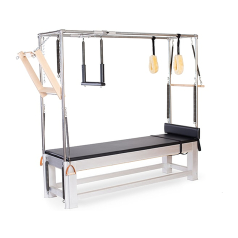
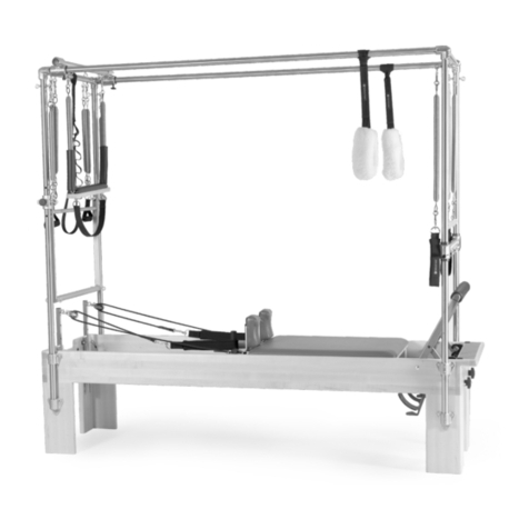
Figure A: Contrology Reformer with Tower
Contact Us
1-800-PILATES | +1-916-388-2838
pilates.com | info@pilates.com
17638-B | 2021-09
Balanced Body, Inc
Sacramento, CA
001-916-388-2838
EC
EMERGO EUROPE
Molenstraat 15
2513 BH, The Hague
The Netherlands
REP
Balanced Body, Inc.
5909 88th St,
Sacramento, CA 95828 USA
STATEMENT OF INTENDED USE
The Contrology® Classical Reformer with Tower device is intended
by the manufacturer to be used by people for the purposes of
physiotherapy, rehabilitation, the prevention, treatment and relief
of injuries, supportive, functional therapy for a disability or for
general strengthening and improving the mobility of the human
body. Should injury occur during usage please report to the
manufacturer and competent authority of the Member State in
which the user and/or patient is established.
DÉCLARATION SPÉCIFIANT L’USAGE PRÉVU
L’appareil Contrology® Classical Reformer with Tower a été conçu
pour être utilisé à des fins de physiothérapie, de réhabilitation, de
prévention, de traitement et de soulagement des blessures, de
thérapie fonctionnelle et de soutien dans le cadre d’un handicap,
ou de renforcement global et d’amélioration de la mobilité du
corps humain. Si une blessure se produit au cours de l’utilisation,
signalér au fabricant et à l’autorité compétente de l’État membre
dans lequel l’utilisateur et / ou le patient est établi.
DICHIARAZIONE DI DESTINAZIONE D’USO
Il dispositivo Contrology® Classical Reformer with Tower è
destinato dal produttore a essere utilizzato dalle persone per
scopi di fisioterapia, di riabilitazione, di prevenzione, trattamento
e sollievo da infortuni, di terapia di sostegno e funzionale per una
disabilità o di rinforzo e miglioramento generali della mobilità del
corpo umano. In caso di infortuni durante l’utilizzo, Rapporto al
produttore e all’autorità competente dello Stato membro in cui è
stabilito l’utilizzatore e / o il paz iente.
DECLARACIÓN DE USO PREVISTO
El dispositivo Contrology® Classical Reformer with Tower está
diseñado con fines de fisioterapia, rehabilitación, prevención,
tratamiento y alivio de lesiones, terapia de apoyo y funcional para
una discapacidad o para el fortalecimiento general y la mejora de
la movilidad del cuerpo humano. En caso de que se produzcan
lesiones durante su uso, Reporte al fabricante y a la autoridad
competente del Estado miembro en el que está establecido el
usuario y / o paciente.
ANGABE DER BESTIMMUNGSGEMÄSSEN
VERWENDUNG
Das Gerät Contrology® Classical Reformer with Tower wurde vom
Hersteller für die Verwendung durch Personen zu Zwecken der
Physiotherapie, der Rehabilitation, der Vorbeugung, Behandlung
und Linderung von Verletzungen, der unterstützenden,
funktionellen Therapie bei einer Behinderung oder zur
allgemeinen Stärkung und Verbesserung der Mobilität des
menschlichen Körpers vorgesehen. Sollten bei der Anwendung
Verletzungen auftreten, Bericht und der zuständigen Behörde des
Mitgliedstaats gemeldet, in dem der Benutzer und / oder Patient
ansässig ist.
2
REFORMER PARTS LIST
DESCRIPTION PART NO. QTY
Reformer Frame N/A 1
Carriage Assembly N/A 1
Shoulder Assembly (pair) 17976 1
Mat Conversion N/A 1
Frame foot spacer pads 16839 4
36” Wooden Pole 16457 1
1/4” Black Kneeling Pad 10248 2
Sitting Box 16147 1
Footstrap 16102 2
Extension Straps 16152 2
Leather Straps (pair) 16153 1
Leather Handles with straight wood
(pair) 16154 1
Contrology Reformer Springs 16228 4
Contrology Springbar 16100 1
Wooden Gear Block Stopper 16343 1
Foam Spacer, Sitting Box N/A 2
Legs, Mat Conversion 16903 4
Mat Castor Cover 17644 1
* 86” Reformer: (Leather Straps P/N: 16360, Carriage Block P/N:
16484, Mat Conv. P/N: 17412). 89” Reformer: (Leather Straps P/N:
16361, Carriage Block P/N: 16505, Mat Conv. P/N: 17414)
INSTALL THE CARRIAGE
Clean all the carriage wheels and the metal rail surfaces of
the frame. Carefully place the carriage into the frame with the
headrest facing away from the footbar.
INSTALLING/REMOVING THE SHOULDER RESTS
1. On the bottom of the shoulder rest brackets, there are
protruding studs. These fit into the plate and secure the
shoulder rest. Lower the shoulder rest so the studs fit into the
key holes on the plate on the carriage. Slide the shoulder rest
away from the carriage pad until it stops. See Figure 1.
2. Secure the shoulder rest by turning the post clockwise until
tight. See Figure 2. Overtightening these will make them
difficult to remove. They should be snug but not too tight.
3. To remove the shoulder rests, turn the posts counter-
clockwise 1-2 turns, gently slide the shoulder rest towards the
carriage. Then gently lift the shoulder rest up and out of the
key holes.
Note: The shoulder rests can be installed in two positions.
One position is wider and more comfortable for broad shoulders.
Swapping the left and right shoulder rests will change between
standard and wide configuration.
INSTALL THE STRAPS
Place the handles on the
shoulder rests posts. Insert the
end of the strap with the
O-ring up and into the caster
opening from the bottom. The
rough side of leather should be
facing the caster wheel. As you
push the strap up, spin the
caster wheel towards the
carriage to assist with feeding
the strap in the wheel
assembly. See Figure 3. Once
the O-ring is through the
caster bring it towards the
carriage and connect it to the
handle clip on that side of the
reformer.
Guide the strap to the eye bolt
on the underside of the carriage.
Connect the Quick Link clip to
the eye bolt on the same side of
the carriage as shown in Figure 4.
Repeat on other side.
Figure 1
Figure 2
Figure 3
Figure 4
3
ATTACH THE SPRINGS TO THE UNDERSIDE OF THE
CARRIAGE
Attach one spring to one
slot in the bracket on the
underside of the carriage
as shown in Figure 5. The
open end of the spring hook
should be facing down.
Repeat for other springs.
INSTALL THE SPRINGBAR
Place the springbar with hook ends facing up into the gear angle
as shown in Figure 6. Connect at least (1) spring to an eye bolt on
the springbar.
CARRIAGE BLOCKS
The Carriage Block at the head end of the Reformer is installed
on the frame to limit the distance the carriage can travel, see
Figure 7. There are two lengths: the Medium Carriage Block
comes with the 86” and Long Carriage Block comes with the 89”
Reformer. Not intended, but can be used on 80” Reformers, must
purchase separately.
The Gear Block, used by all Reformer lengths, at the foot end is
installed on the left side rail of the gear positions as shown in
Figure 8. The Gear Block has two settings, short and long. Figure
8 shows the short position, when spring bar is in the middle or
“B” position. Flip the Gear Block over to get the long position, for
use when the springbar is in the last or “C” position.
The Carriage Blocks are
most commonly used for
clients who have a limited
range of motion, or to stop
the carriage from traveling
too far. The Gear Block is
used to change the carriage
starting position.
INSTALL FOOTSTRAPS
Two footstraps are included
with the Reformer. Clip one
end of the strap to one eye
bolt on the inside foot end
of the frame, the other clip
to the other eye bolt on the
opposite side of frame end.
Repeat for second footstrap,
see Figure 9.
HOW TO INSTALL EXTENSION STRAP
Remove the handles from both straps. Fold the extension strap
in half and insert the clip into and through the D-ring, see Figure
10. Attach the clip to the O-ring on the end of the strap. See
Figure 11. Repeat this process for other strap.
Figure 5
Figure 6
Figure 7
Figure 8
Figure 9
Figure 11Figure 10
4
INSTALL THE OPTIONAL JUMPBOARD (86”/218cm and
89”/226cm models only)
Correct installation of the jumpboard is very important. Lay the
footbar flat down on the Reformer. Install the jumpboard down
into the installed bracket on the inside of the foot end of the
Reformer. The padded side should face the carriage. Properly
installed the jumpboard will rest on the foot plate bracket, see
Figure 12.
FIXED STRAP HOOK (OPTIONAL)
This Reformer comes with
an option to install a Fixed
Hook for the straps. This
can be installed as shown in
Figure 13. Non-Adjustable
Strap Kit (210-146). If your
machine came with a Fixed
Strap Hook pre-installed,
it may be removed and a
Kit for Adjustable Straps
(210-145) may be purchased
separately.
LEVELING
If desired or needed, there are (4) square pads that can be placed
one under each leg; if your machine is not sitting level on your
floor, or if the machine is moving during use.
Figure 12
Figure 13
5
TOWER PARTS LIST
DESCRIPTION PART NO. QTY
Tower Assembly N/A 1
Vertical Tower Tubes 16968 2
Horizontal Tower Tube 17323 1
Push Through Bar 17598 1
Roll Back Bar 17110 1
Push Through Bar Springs 16913 3
Roll Back Bar Springs 16910 2
Light Arm Springs 17109 2
Light Leg Springs 17094 2
Cotton Loop (pair) 16992 1
Storage Chain w/ Quick Link 17648 1
Safety Chain w/ Quick Link 17649 2
Leather Contoured Handle
Assembly (pair) 17115 1
Allen Wrench, 5/32” 13778 1
Allen Wrench, 3/16” 13777 1
1/4-20 x 5/8” Button Screw 15223 4
Eye Bolt 2-1/2” long 13744 2
Lock Washer 13633 2
Hex Nut, 1/4”-20 13635 2
INSTALL THE TOWER
1. Remove the Tower tubes with Push Through Bar from the box.
Do not cut the tie between the Push Through Bar and the tubes
or else it can swing when lifting and hit you or someone else. On
the outside of the two vertical tubes there will be (2) threaded
holes, these will face out away from the machine when installed.
2. Insert the tubes into the
tower brackets on the head
end of the machine, making
sure the threaded holes are
facing you when installing.
Lower the tubes carefully
all the way down the tower
brackets. They will touch the
ground. See Figure 14.
3. Use the provided (4) 1/4”-20 x 5/8” long screws, to secure the
tubes to the brackets. It may be necessary to slightly lift the
tube to align the holes. Start all the screws by hand before
fully tightening. Use the 5/32” Allen wrench to tighten all (4)
screws to the brackets. After screws are tight, remove the tie
and packaging from Push Through Bar. Install the 2 1/2” long
eye bolts with a nut and a lock washer up against the tube in
the bottom hole of brackets. Make sure that the eye bolt is
aligned vertically when tight.
4. Attach the Roll Back Bar Springs to the Roll Back Bar and
install the springs to the outer eye bolts on the top cross tube.
See Figure A and 15 for reference.
5. Install the Arm Springs to the desired position on the tower
and attach the handles to the springs. See Figure A and 15 for
reference.
6. install the Leg Springs to the tower on the desired eye bolts
and install the cotton loops to these springs. See Figure A and
15 for reference.
7. Attach the Storage Chain (shortest chain) to the middle eye
bolt on the top cross tube using the Quick Link.
8. Attach the Safety Chains, one to each of the outer eye bolts
on the top cross tube using the Quick Links.
9. Attach the Push Through Bar Spring with the quick link to one
of the top tube outer eye bolts. The other (2) Push Through
Bar springs will connect to the reformer frame eye bolts using
the open hooks. See Figure 16 for reference.
Figure 15: A) Leg Springs (the longest springs)
B) Roll Down Bar Springs (have 2 dog clips attached)
C) Arm Springs (only 1 dog clip attached)
A)
B)
C)
E) F) Figure 16: D) Push Through Bar Springs
E) Quick link
F) Double harness snap
Quick Link Double
Harness Snaps
Closed hooks both ends
1 open hook (left) and 1 closed hook (right)
D)
Figure 14
6
HOW TO INSTALL YOUR WIRE STOPS ON YOUR
CONTROLOGY SPRINGS
PARTS INCLUDED:
DESCRIPTION PART NO. QTY
Wire Stop 17922 3
10-24 Set Screw 17931 7
3/32” Allen Wrench 17930 1
Start to thread a provided set screw into each wire stop, install the
set screw into the wire stop so about 1/4 of the set screw sticks out.
(Note they might be already in the wire stops, if they are, ensure
they are not going into the middle opening of the wire stop)
Go to the top mounted spring attached to your machine, See
Figure 6. Install a wire stop onto the end of the open hook. Slide
the middle opening of the wire stop onto the wire so that the wire
end is barely coming out the underside of the wire stop.
Make sure the wire stop length of the body is perpendicular to
the wire, See Figure 7. Use the provided Allen wrench to tighten
the set screw. Ensure the set screw is very tight to prevent them
from coming loose.
Repeat the above steps for the other springs with open ends.
There are (3) Push through bar springs, each getting one on the
frame end of the spring.
Figure 6
Figure 7
ASSEMBLY MAT CONVERSION
1. You will need to install legs on your Mat Conversion pad before
using.
2. Find the (4) feet with a thread sticking out and thread them into
the corner inserts on the bottom side of the mat conversion.
3. Turn them clockwise until tight. Hand tight is okay.
See Figure 17.
Figure 17
7
INSTALLING THE MAT CONVERSION
1. Remove all springs that are attached to the spring bar.
2. Remove the shoulder pads and brackets from the carriage.
3. Roll the carriage to the head end of the frame. When close to
the end of the frame, drop in the Mat Caster Cover assembly
between the frame and the carriage. This will act as a stopper
for the carriage and cover the casters. See Figure 18. The flaps
go over shoulder plates, when the shoulder rests are removed.
4. Lay the footbar flat on the inside of the frame as shown in
Figure 19. If using the wooden gear stopper, remove this so the
footbar can lay lower in the frame.
5. Lift and install the Mat Conversion inside the frame. There are
(2) cutouts on the underside of the mat to clear the footbar
pivots, ensure these are on the foot end of the machine when
installing. See Figure 20 for reference
CONVERT BACK TO A REFORMER
Remove the Mat Conversion, flip the footbar back into position
and ensure the kickstand is secure, remove the Mat Caster cover,
roll the carriage to home position and attach at least one spring
to the spring bar.
INSTALLING YOUR SITTING BOX SPACERS:
1. Find the (2) foam spacers, see Figure 21 for what they look like.
2. Flip over the sitting box and place the foam spacer on the
bottom with the PSA paper facing up. Slide this under the
wood rib in the middle. See Figure 22.
3. Once the cut in the foam spacer is centered under the wood
rib, rotate the foam spacer up 90 degrees and push against
the wood side. See Figure 23
4. Repeat this process of the other spacer.
5. The foam spacer reduces the movement between the sitting
box and the shoulder posts when installed in Short Box on the
carriage.
6. If desired, the PSA paper can be removed and the adhesive
can secure the foam spacer to the side of the sitting box.
The foam spacer fits snug in the sitting box area, so it is not
necessary to do this, but can be if desired
Figure 18
Figure 19
Figure 20
Figure 21
Figure 22
Figure 23
8
Cleaning and Maintenance
CLEANING
You can extend the life of upholstery by keeping it clean and free
of dirt, oil and perspiration. After each use, wipe down all skin
contact parts, including carriage, shoulder and head rests.
Equipment upholstery is coated with BeautyGard®, which offers
antibacterial protection. Balanced Body Clean™ is an all-purpose
cleaner that is 100% natural, organic and biodegradable. It cleans,
disinfects and removes dirt, grease and oil and will extend the life of
your upholstery. A mild soap and water solution may also be used.
»Be sure to dry thoroughly.
»For heavier soiling please call Balanced Body Technical
Support.
»Wheel tracks and wheels should be cleaned regularly with a
cloth to ensure that tracks smoothly and quietly.
»Wash footstrap regularly. Place in pillowcase, wash on gentle
cycle, air dry.
»Be sure to inspect springs regularly.
If you have any questions on cleaning or maintenance, please call
Balanced Body Technical Support.
LUBRICATION AND ADJUSTMENT
As needed, lubricate side wheels with 3-in-1 oil.
It is not recommended to lubricate the carriage rolling whe els, do
so at your own risk.
IN CASE OF FREIGHT DAMAGE
If there is freight damage, make certain you keep all packaging
material. Please call Balanced Body immediately.
9
WARNING: This machine is potentially dangerous, and Balanced
Body Inc. assumes no liability towards use or misuse. If you are
not fully aware of the safety issues and use of this machine, do not
use it. Use only with qualified instructor supervision. Please refer
to the Additional Usage and Safety section for more information.
AVERTISSEMENT : Cette machine est potentiellement
dangereuse et Balanced Body Inc. n’assume aucune
responsabilité quant à son utilisation ou sa mauvaise utilisation.
Si vous ne vous êtes pas pleinement familiarisé avec les
questions de sécurité et l’utilisation de cet appareil, ne l’utilisez
pas. Utilisez cet appareil uniquement sous la supervision d’un
instructeur qualifié. Pour plus d’informations, veuillez vous
reporter à la section Utilisation et sécurité.
ATTENZIONE: questo macchinario è potenzialmente pericoloso
e Balanced Body Inc. non si assume la responsabilità in caso
di utilizzo o di utilizzo improprio. Se non siete ben informati
sulla sicurezza e l’utilizzo di questo dispositivo, non utilizzatelo.
Utilizzatelo solo sotto la supervisione di un istruttore qualificato.
Per ulteriori informazioni fate riferimento all’utilizzo addizionale
e alla sezione dedicata alla sicurezza.
ADVERTENCIA: Esta máquina es potencialmente peligrosa, y
Balanced Body Inc. no asume ninguna responsabilidad por su uso
o mal uso. Si no conoce completamente los asuntos relativos a
la seguridad y el uso de este dispositivo, no lo utilice. Úselo solo
bajo la supervisión de un instructor calificado. Consulte la sección
Otros usos y seguridad para obtener más información.
ADDITIONAL SAFETY ANDUSAGE
For additional usage and safety information or to view complete
equipment manual translations (USER GUIDE #17639), please
visit https://contrology.pilates.com/support. For printed instruc-
tions, contact your seller.
Per ulteriori informazioni sull’uso e sulla sicurezza, oppure per
consultare le traduzioni complete del manuale (MODE D’EMPLOI
#17639), visitare https://contrology.pilates.com/support. Pour
obtenir desinstructions imprimées, contactez votre vendeur.
Pour plus d’informations sur l’utilisation et les consignes de
sécurité ou pour consulter le manuel integral disponible (GUIDA
UTENTE #17639),veuillez https://contrology.pilates.com/sup-
port . Per le istruzioni stampate contatta il tuo venditore.
Para obtener más información sobre el uso y la seguridad, o
para ver las traducciones completas del manual (GUIA DEL
USUARIO #17639), visite https://contrology.pilates.com/sup-
port. Para obtener instrucciones impresas, comuníquese con su
vendedor.
Für zusätzliche Informationen zu Gebrauch und Sicherheit oder
vollständige Übersetzungen der Gebrauchsanweisung (BE-
NUTZERHANDBUCH #17639) besuchen https://contrology.
pilates.com/support. Für gedruckte Anweisungen wenden Sie
sich anIhrenVerkäufer.
Scan for Patent Datainformation:
ACHTUNG: Dieses Gerät ist potenziell gefährlich, und Balanced
Body Inc. übernimmt keine Haftung für dessen Gebrauch oder
Missbrauch. Wenn Sie mit den Sicherheitsrisiken und dem
Gebrauch dieses Geräts nicht völlig vertraut sind, verwenden
Sie es bitte nicht. Gebrauchen Sie es nur unter Aufsicht eines
qualifizierten Trainers. Für zusätzliche Informationen lesen Sie bitte
den Abschnitt Zusätzliche Gebrauchs- und Sicherheitshinweise.
QUESTIONS?
Please call Balanced Body Technical Support at
1-800-PILATES (U.S.) or +1-916-388-2838 (International).
10

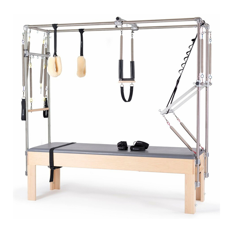
Other Balanced Body Medical Equipment manuals

Balanced Body Reformer Trapeze Combination Administrator Guide

Balanced Body

Balanced Body Reformer Trapeze Combination Administrator Guide

Balanced Body Ron Fletcher Reformer User manual

Balanced Body

Balanced Body Ron Fletcher Reformer User manual

Balanced Body Allegro 2 Reformer User manual

Balanced Body

Balanced Body Allegro 2 Reformer User manual

Balanced Body Contrology Reformer User manual

Balanced Body

Balanced Body Contrology Reformer User manual

Balanced Body Contrology Cadillac User manual

Balanced Body

Balanced Body Contrology Cadillac User manual

Balanced Body Clinical Reformer Administrator Guide

Balanced Body

Balanced Body Clinical Reformer Administrator Guide

Balanced Body Clinical Reformer User manual

Balanced Body

Balanced Body Clinical Reformer User manual

Balanced Body Contrology Cadillac Administrator Guide

Balanced Body

Balanced Body Contrology Cadillac Administrator Guide

Balanced Body Cadillac Administrator Guide

Balanced Body

Balanced Body Cadillac Administrator Guide

Balanced Body Contrology User manual

Balanced Body

Balanced Body Contrology User manual

Popular Medical Equipment manuals by other brands

Rigel Medical UniPulse 400 quick start guide

Rigel Medical

Rigel Medical UniPulse 400 quick start guide

BIOTRONIK Amvia Stellar UDI-DI Technical manual

BIOTRONIK

BIOTRONIK Amvia Stellar UDI-DI Technical manual

Gima 27850 manual

Gima

Gima 27850 manual

Argos Omega Plus Operator's manual

Argos

Argos Omega Plus Operator's manual

Cardioline AR 600 Technical & service manual

Cardioline

Cardioline AR 600 Technical & service manual

Logiquip DRI-STOR Use & care guide

Logiquip

Logiquip DRI-STOR Use & care guide

Vapotherm Precision Flow Hi-VNI Instructions for use

Vapotherm

Vapotherm Precision Flow Hi-VNI Instructions for use

Autel DiagLink OBDII instruction manual

Autel

Autel DiagLink OBDII instruction manual

Sirona DAC UNIVERSAL operating instructions

Sirona

Sirona DAC UNIVERSAL operating instructions

Coala Life Coala Get started

Coala Life

Coala Life Coala Get started

Nellcor OxiMax N 5500 Service manual

Nellcor

Nellcor OxiMax N 5500 Service manual

WHT extriCARE 3600 troubleshooting guide

WHT

WHT extriCARE 3600 troubleshooting guide

Augustine Surgical HotDog WC7 Series User and technical manual

Augustine Surgical

Augustine Surgical HotDog WC7 Series User and technical manual

SOPRO COMEG 640-45L user manual

SOPRO COMEG

SOPRO COMEG 640-45L user manual

Invacare SoftCloud Ace user manual

Invacare

Invacare SoftCloud Ace user manual

ConMed hyfrecator 2000 Operator's manual

ConMed

ConMed hyfrecator 2000 Operator's manual

ADC ADSCOPE 600 Instructions for use

ADC

ADC ADSCOPE 600 Instructions for use

Sirona SIROLaser Xtend operating instructions

Sirona

Sirona SIROLaser Xtend operating instructions

manuals.online logo
manuals.online logoBrands
  • About & Mission
  • Contact us
  • Privacy Policy
  • Terms and Conditions

Copyright 2025 Manuals.Online. All Rights Reserved.