BALDER BH3 User manual

WELDING HELMET
Instruction Manual
METINĀŠANAS AIZSARGMASKA
Instrukciju rokasgrāmata
SCHWEISSERSCHUTZMASKEN
Bedienungsanleitung
MASQUE DE SOUDEUR
Mode d’emploi
HEŁM SPAWALNICZY
Instrukcja użytkowania
MASCHERA PROTETTIVA PER SALDATURA
Manuale di istruzioni
SVÁŘECÍ KUKLA
Návod k použití
CASCO DE SOLDADURA
Manual de instrucciones
СВАРОЧНАЯ МАСКА
Руководство пользователя
SVETSNINGSHJÄLM
Instruktionsmanual
MASCA DE SUDURĂ
Manual de instrucţiuni
HITSAUSMASKI
Käyttöopas
SUVIRINIMO ŠALMAS
Naudojimo instrukcija
SVEISEHJELM
Bruksanvisning
ZVÁRACIA HELMA
Návod
LASHELM
Handleiding
HEGESZTŐPAJZS
Kezelési útmutató
GB
LV
DE
FR
PL
IT
CZ
ES
RU
SE
RO
FI
LT
NO
SK
NL
HU
BALDER BH3


WELDING HELMET
Instruction Manual 4
20
36
52
68
148
84
164
100
180
228
116
196
244
132
212
260
METINĀŠANAS AIZSARGMASKA
Instrukciju rokasgrāmata
SCHWEISSERSCHUTZMASKEN
Bedienungsanleitung
MASQUE DE SOUDEUR
Mode d’emploi
HEŁM SPAWALNICZY
Instrukcja użytkowania
MASCHERA PROTETTIVA PER SALDATURA
Manuale di istruzioni
SVÁŘECÍ KUKLA
Návod k použití
CASCO DE SOLDADURA
Manual de instrucciones
СВАРОЧНАЯ МАСКА
Руководство пользователя
SVETSNINGSHJÄLM
Instruktionsmanual
MASCA DE SUDURĂ
Manual de instrucţiuni
HITSAUSMASKI
Käyttöopas
SUVIRINIMO ŠALMAS
Naudojimo instrukcija
SVEISEHJELM
Bruksanvisning
ZVÁRACIA HELMA
Návod
LASHELM
Handleiding
HEGESZTŐPAJZS
Kezelési útmutató
GBRULVSE PLLTITNO DEROFRFI CZSKESNLHU
3

PRECAUTIONS
Never place the helmet or the autodarkening welding filter on hot surface.
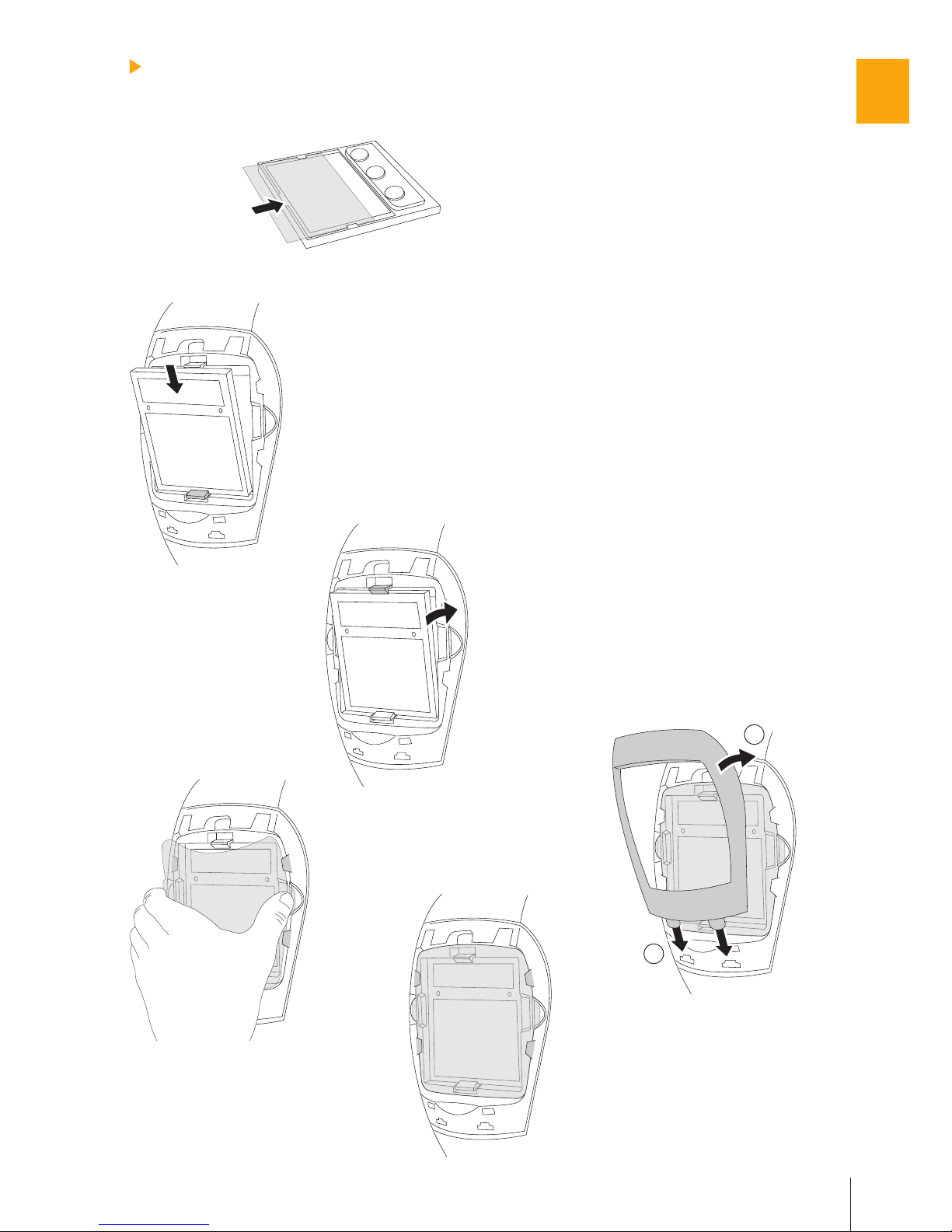
Scratched or damaged protection screens should be regularly replaced by original BALDER
ones. Before using the new protection screen, make sure to remove any additional protection
foil from both sides.
Use only BALDER BH3 within the temperature range of -10°C to +60°C.
Do not expose the autodarkening welding filter to liquids and protect it from dirt.
Use only original BALDER spare parts. In case of doubt, please contact your BALDER author-
ized dealer.
Failure to follow these instructions will invalidate the warranty. BALDER does not accept
responsibility for any problems which may arise from applications other than welding, or if
the instructions for use are not strictly followed. The BALDER BH3 welding helmet is manu-
factured to protect the welder’s face against spatters and hazardous ultraviolet and infrared
rays emitted during the welding process. It is not intended to be used as a protection against
impact, flying particles, molten metals, corrosive liquids or hazardous gases.
Materials which may come into contact with the wearer’s skin could cause allergic reactions to
susceptible individuals.
Welding helmet worn over standard ophthalmic spectacles may transmit impact, thus create a
hazard to the wearer.
If the helmet and the protection screen both do not carry the B marking, then only the S mark-
ing is valid.
BEFORE WELDING
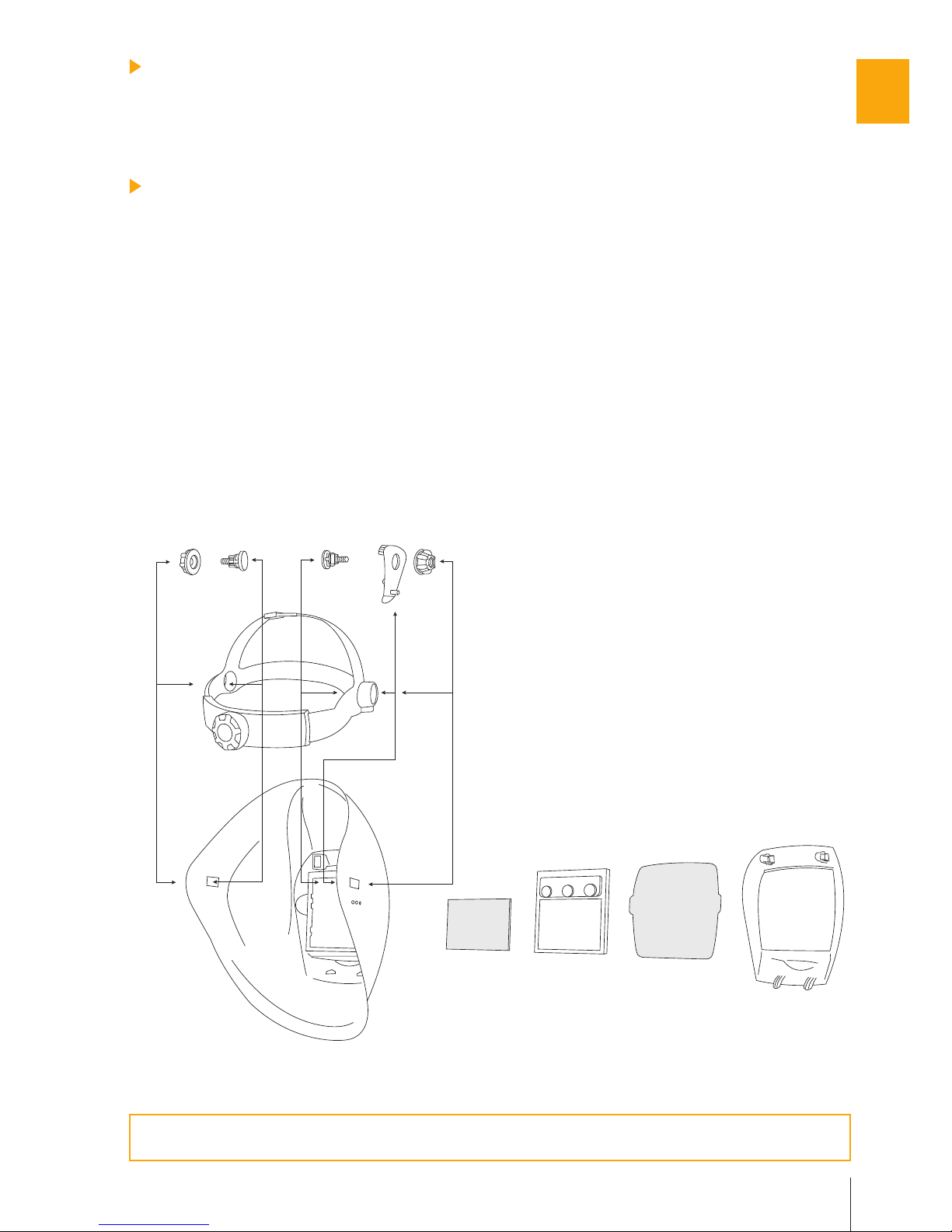
Ensure that the helmet is correctly assembled and that it completely blocks any accidental
light. In the front, light may enter the helmet only through the viewing area of the autodarken-
ing welding filter.
Adjust the headgear to ensure maximum comfort and to provide the largest field of vision.
Select a suitable welding filter for the shield. Dimensions of the filter: 110x110 mm (see
BALDER leaflet).
Check the prescribed shade level for your welding application and adjust your autodarkening
filter accordingly (see the table with recommended shade levels).
STORAGE
When not in use the filter should be stored in a dry place within the temperature range of -20°C to
+65°C. Prolonged exposure to temperatures above 45°C may decrease the battery lifetime of the
autodarkening
welding filter. It is recommended to keep the solar cells of the
autodarkening
weld-
ing filter in the dark or not exposed to light during storage in order to maintain power down mode.
This can be achieved by simply placing the filter face down on the storage shelf.
MAINTENANCE AND CLEANING
It is always necessary to keep the solar cells and the light sensors of the autodarkening welding
filter free of dust and spatters: cleaning can be done with a soft tissue or a cloth soaked in mild
detergent (or alcohol). Never use aggressive solvents such as acetone. BALDER filters should
always be protected from both sides by protection screens (polycarbonate or CR39), which
should also be only cleaned with a soft tissue or cloth. If protection screens are in any way dam-
aged, they must be immediately replaced.
For your protection and maximum efficiency, please read this informa-
tion carefully before use.
•
•
•
•
•
•
•
•
•
•
•
•
•
4
GB

A A CC B
D
E
F
BH3 HELMET AND HEADGEAR ASSEMBLY
Insert screws (A) through the openings in the headgear (D).
Insert the headgear (D) into the helmet shell (F) as shown in figure 1 and push the screws (A)
through the rectangular openings in the helmet shell.
Put the tilt adjustment (B) on the right side between the screw (A) and helmet shell (F). Make
sure that a small pin is fixed in one of the three holes in the helmet shell. Choose the right hole
for your maximum comfort.
Tighten the nuts (C) on the screws (A). Before adequately tightening them, place the headgear
at the most comfortable distance from the filter opening by adjusting the possition of headgear
within the two rectangular holes in the helmet shell.
The headgear size (D) can be adjusted by turning the rear wheel (E) in order to fit any head
size. Press the wheel and hold it while turning, release the wheel when reaching the position
of maximum comfort, so that it will lock in the required position.
Figure 1
The headgear is equipped with a replaceable sweatband. Sweatbands are available
through your local dealer.
WARRANTY
The warranty period of BALDER products is three years. Failure to follow these instructions may
invalidates the warranty. BALDER does not accept responsibility for any problems, which may
arise from applications other than welding.
1.
2.
3.
4.
5.
5
GB

G
H
Figure 1
A
A
E
C1
C1
C2
C2
D
D
B
F
BH3 HELMET AND HARD HAT ASSEMBLY
/ BH3 HH - version of BH3 helmet with Safety cap concept /
If you have purchased the BH3 welding helmet in combination with hard hat, the Speedy
Loop will be replacing the standard headgear. Please note that the holes in the helmet as
well as bolts, nuts and washers are different from those of the standard headgear.
Insert screws (A) through the openings in the Speedy Loop (E).
Insert the Speedy Loop (E) into the helmet shell (F) as shown on figure 1 and push the screws (A)
through the rectangular openings in the helmet shell.
Put the tilt adjustment part (B) on the right side between the Speedy loop (E) and the helmet shell
(F). Make sure that a small pin is fixed in one of the four holes in the tilt adjustment part. Choose
the right hole for your maximum comfort.
Tighten the nuts (D) and washers (C1, C2) on the screws (A).
Place the helmet with speedy loop over the hard hat as shown on figure 2. Left and right “click”
will hold the position. If necessary, adjust the extent/diameter of Speedy Loop for optimum grip
on the helmet. Adjust the distance from the face to the welding helmet by coordinated extension/
reduction of front and rear part of Speedy Loop in order to find the most comfortable position.
The headgear of the hard hat (G) can be adjusted by turning the rear wheel (H) in order to fit any
head size. Press the wheel and hold it while turning, release the wheel when reaching the posi-
tion of maximum comfort, so that it will lock in the required position.
The headgear is equipped with a replaceable sweatbands. Sweatbands are available
through your local dealer.
Figure 2
1.
2.
3.
4.
5.
6.
6
GB

1.
2.b
3.a
2.a
3.b
4.
1
2
AUTODARKENING WELDING FILTER AND PROTECTION SCREENS
ASSEMBLY / Grand DS, Power DS /
Slide in the inner protection screen on the in-
ner side of the autodarkening welding filter as
shown in figure (1.).
From the external side of the helmet shell, insert
the welding filter in the filter opening.
Begin by
inserting the filter at the bottom, so that it clicks in
the bottom clip (2.a); then push in the top part so
that it clicks into the top clip (2.b).
Insert the external protection screen into its po-
sition with four side holders. Hold the protection
screen with your thumb and middle finger and
place it on the side of your thumb into the slots
of both side holders. The indent of the helmet
shell provides the necessary space for your
thumb (3.a). With your middle finger bend the
protection screen and with the aid of the other
fingers place it in both side slots (3.b).
Close the helmet shell with the external frame.
Insert the bottom two pins in the lowest two
openings of the helmet shell and push the top
part of the frame into the helmet shell so that
the two upper pins click in the pin openings on
both sides (2x click) (4.).
1.
2.
3.
4.
7
GB

1.
2.b
3.a
2.a
3.b
AUTODARKENING WELDING FILTER AND PROTECTION SCREENS
ASSEMBLY / Grand GDS, Grand ES, Power GDS, Power ES /
Slide in the inner
protection
screen on the
inner side of the autodarkening welding filter as
shown in figure (1.).
Gently fold the printed circuit board of the
external control behind the filter so that it is
positioned inside the helmet shell before you.
Insert the filter in its opening. Begin by insert-
ing the filter at the bottom, so that it clicks in
the bottom clip (2.a); then push in the top part
so that it clicks into the top clip (2.b).
Insert the external protection screen into its
position with four side holders. Hold the protec-
tion screen with your thumb and middle finger
and place it on the side of your thumb into the
slots of both side holders. The indent of the
helmet shell provides the necessary space for
your thumb (3.a). With your middle finger bend
the protection screen and with the aid of the
other fingers place it in both side slots (3.b).
Close the helmet shell with the external frame.
Insert the bottom two pins in the lowest two
openings of the helmet shell and push the top
part of the frame into the helmet shell so that
the two upper pins click in the pin openings on
both sides (2x click) (4.).
Insert the middle part of the external control
housing in its opening on the exterior side of
the helmet shell (5.).
Insert the electronic circuit board with poten-
tiometers in the middle part of the external
control housing (6.).
While pressing the electronic board, insert the
4 knobs to the potentiometers from the outside.
Take care, that the knobs are inserted cor-
rectly. Check that the final position of the marks
on the knob correspond to the printing on the
external controls housing (7.).
Insert the external part of the external control
housing so that it fits on the middle part of the
external control housing (8.).
Place the internal part of the external control
housing correctly on the middle part of the
external control housing and fix it with four
screws (9.).
1.
2.
3.
4.
5.
6.
7.
8.
9.
8
GB

6.
9.
5.
7.
8.
4.
1
2
9
GB

1.a
1.b 2.
1
22
1
PROTECTION SCREEN REPLACEMENT
Remove the external frame. From the internal
side of the helmet shell squeeze the two pins
towards each other, release the frame and
slightly push it out (1.a), then rotate it to release
the bottom two pins (1.b).
Hold the protection screen with your thumb and
middle finger on the side extensions along the
indents in the helmet shell intended for your fin-
gers. Press on the protection screen to slightly
bend it and remove it from the holder slots (2.).
Insert a new protection screen and close the
cover as described in the previous section,
under points 3 and 4.
During assembly of the helmet and welding
filter, or during the replacement of the pro-
tection screens, make sure that all parts are
firmly in place thus preventing any light from
entering the helmet. Should there still be any
light entering, repeat the procedure until the
problem is eliminated, otherwise the helmet
must not be used for welding. Before placing
the new protection screens, always remove
the protection layers from both sides.
BH3 AIR HELMET ASSEMBLY
/ BH3 AIR - version of BH3 helmet with integrated air supply system for combi-
nation with Clean-air Power unit set /
If you have purchased the BH3 helmet in a combination with the integrated air supply
system, the helmet will be additionaly equiped with integrated airduct, hose connector
and air grill. Balder does not except responsibility for the results of a service performed
by anyone other than a Balder authorised service agent. Failure to follow this instruc-
tions may invalidate the warranty.
1.
2.
3.
10
GB

AA
C
C
B
D
X
E
F
ZZ
Y
In order to assure adequate sealing in the hood
and meeting the safety standards, the BH3 AIR
must be additionally equiped with a pair of wash-
ers. The washers are attached into the two upper
inner pins of the external control frame.
Figure 1
Figure 2
WASHERS ASSEMBLY
The BH3 AIR helmet assembly is similar as described in the section BH3 HELMET AND HEAD-
GEAR ASSEMBLY. Besides some additional integrated parts, (airduct, hose connector and air
grill), which are to be assembled by the manufacturer only, the BH3 AIR helmet has also a hose
holder (X), face seal (Y) and a pair of washers (Z).
Hose holder (X) needs to be fixed onto the headgear (D) between the headgear (D) and the nut
(C), as shown on figure 1. The hose holder is designed in a way to allow use on either side of the
headgear, depending on the type of Clean-air power unit.
Face seal must be properly assembled with the BH3 AIR helmet. It’s position related to the helmet
and the headgear is evident from figure No.1, while exact position related to the BH3 AIR helmet,
airduct and hose holder is precisely described in the next section FACE SEAL REPLACEMENT.
11
GB

1.
2. 3.
6.
5.
4.
FACE SEAL REPLACEMENT
MOUNTING OF THE HOSE
Both available versions of face seal (Standard and Flexi) have exactly the same plastic face
seal holder, so the replacing procedure is the same for both. In order to be able to observe
the details better, the assembly schemes will show the face seal holder without the face
seal (fabric part).
Remove the headgear in the oposite order as described in the section BH3 HELMET AND
HEADGEAR ASSEMBLY.
Pull the lower part of the face seal holder to release it from the airduct (1.).
Release the face seal holder from the two outside upper latches (2.).
Pull the face seal holder from the two inside upper latches (3.).
Take the new face seal and push the inner upper side of the face seal holder into the two up-
per inside latches (4.).
Push the outside upper part of the face seal holder into the two outside upper latches (5.).
Slide the lower part of the face seal holder into the gap between the helmet and airduct (6.).
Assemble the headgear as described in the section BH3 HELMET AND HEADGEAR AS-
SEMBLY.
Screw in the hose of PAPR (hose comes with
the Clean-air power unit set) as shown on the
scheme. Adjust the length of the hose between
the hose connector and the hose holder so you
achieve the maximum comfort. We recommend
this length to be 25-30 cm of non stretched hose,
so the upper loop would not be too long, as the
lenght should allow comfortable lifting of the
helmet. It is recommended that the length of the
hose from the hose connector to the Clean-air
power unit is adjusted, so that the hose follows
well the user’s back without being stretched.
Once the hose is placed into the hose holder,
adjust the height of the hose by simply pulling the
hose trough the hose holder upward or down-
wards. Fine adjustment of shape of the loop can
be achieved by turning the hose left or right.
1.
2.
3.
4.
5.
6.
7.
8.
12
GB

AUTODARKENING WELDING PROTECTION FILTER
OPERATION
BALDER autodarkening welding protection filters operate on the basis of a liquid crystal light
shutter that protects the welder’s eyes against intense visible light emitted during the welding
process. In combination with the permanent passive IR/UV filter, it protects against hazardous
infrared (IR) and ultraviolet (UV) light. The protection against harmful radiation is present regard-
less of the shade level or potential malfunction of the filter, beyond the darkest shade number
marked on each specific model.
BALDER autodarkening welding protection filters are manufactured according to EN 379 require-
ments and are CE, DIN as well as DIN Plus certified. They are not intended to be used as a
protection against impacts, flying particles, molten metals, corrosive liquids or hazardous gases.
Replace potentional malfunctioned (check that the autodarkening filter turns dark if you strike the
welding arc) or physically damaged autodarkening welding filter.
Protection screens, both internal and external (polycarbonate or CR39), must be used in
conjunction with the autodarkening filter in order to protect it against permanent damage.
USAGE
An autodarkening welding protection filter built into a welding helmet is considered to be »Per-
sonal Protection Equipment« (PPE) protecting the eyes, face, ears and neck against direct and
indirect hazardous light of the welding arc. In case that you have only bought a filter without the
helmet, you need to select the appropriate helmet designed to be used in combination with an
autodarkening welding protection filter. It has to allow the filter, including the internal and external
protection screens, to be adequately mounted into the helmet. There should be no increased
point tensions caused by the fixing frame or mounting system, as they could cause severe dam-
age to the filter. Make sure that solar cells and photo-sensors are not covered by any part of the
helmet, as this could prevent the proper operation of the filter. If any of these conditions occur,
the filter may not be suitable for use.
FIELD OF APPLICATION
BALDER filters are suitable for all types of electro-welding: covered electrodes, MIG/MAG, TIG/
WIG, plasma welding, cutting and laser welding (only selected models with two shade ranges,
i.e.6-8 and 9-13), except for gas welding.
FUNCTIONS
BALDER filters are supplied ready for use. Check the degree of required protection for
specific welding procedure and if a certain model allows you, select the recommended
shade, light sensitivity as well as opening time delay.
Shade adjustment: Some models (Power DS, Power ES, Grand DS, Grand ES) enable shade
adjustment range from 9 to 13. Selected models Power GDS and Grand GDS have two shade
ranges, i.e. 6-8 and 9-13. It can be adjusted by the knob »Range« which is located on the filter.
The external knob for shade adjustment has two shade ranges (6-8 and 9-13) marked in two dif-
ferent typefaces (positive and negative). The adjustment of the knob »Range« defines the range
which is being used.
Adjustment of sensitivity: Most welding applications can be performed with welding light
sensitivity set to maximum. The maximum sensitivity level is appropriate for low welding current
work, TIG, or special applications. The welding light sensitivity has to be reduced only in some
specific surrounding lighting conditions in order to avoid unwanted triggering. As a simple rule
for optimum performance, it is recommended to set sensitivity to the maximum at the beginning
and then gradually reduce it, until the filter reacts only to the welding light flashes and without
annoying spurious triggering due to ambient light conditions (direct sun, intensive artificial light,
neighboring welder’s arcs etc.).
13
GB

Grand GDS, Power GDS
Grand ES, Power ES, Grand DS, Power DS
Grand GDS, Power GDS
Grand ES, Power ES, Grand DS, Power DS
Grand GDS, Power GDS
Grand ES, Power ES, Grand DS, Power DS
Grand GDS, Power GDS
Grand ES, Power ES, Grand DS, Power DS
Grand GDS, Power GDS
Grand ES, Power ES, Grand DS, Power DS
Grand GDS, Power GDS
Grand ES, Power ES, Grand DS, Power DS
Grand GDS, Power GDS
Grand ES, Power ES, Grand DS, Power DS
WELDING
PROCESS
MMA
CURRENT IN AMPERES
MAG
TIG
MIG heavy metals
MIG light metals
Stainless, AI
Plasma cutting
Micro plasma welding
610 15 30 40 60 70 100 125 150 175 200 225 250 300 350 400
910 11 12 138
910 11 128
910 11 12 13814
910 11 12 13
10 11 12 13
910 11 12 13
4 5 6 7 8 9 10 11 12 13
Opening time delay adjustment: The opening time delay can be adjusted from 0.1 to 1.0 sec-
onds. It is recommended to use a shorter delay with spot welding applications and a longer delay
with applications using higher currents and longer welding intervals. Longer delay can also be
used for low current TIG welding in order to prevent the filter opening when the light path to the
sensors is temporarily obstructed by a hand, torch, etc.
Function welding/grinding
(models Power GDS, Grand GDS only): For these filters, two modes
of operation can be selected: welding or grinding. By selecting the position »Grind«, the filter
switches off and it will not be triggered by the sparks generated during grinding. Before restarting
welding work, the knob should be set back to the »Weld« position.
RECOMMENDED SHADE LEVELS FOR VARIOUS WELDING APPLICA-
TIONS / EN 379 /
LIGHT TRANSMISSION CURVE
0,0001
0,001
0,01
0,1
1
10
100
T[%]
300 400 500 600 700 800 900 1000 1100 1200 1300 1400
λ[nm]
Shade 3
Shade 4
Shade 6
Shade 7
Shade 8
Shade 9
Shade 10
Shade 11
Shade 12
Shade 13
LIGHT STATE
Transmission
Wavelength
DARK STATE
14
GB

Range 9-136-8
BALDER Grand GDS
4/6-8/9-13 BL 1/1/1/1/379
ANSI-Z87.1
Sensitivity
Delay
S
H
A
D
E
Weld
Grind
7.
9.
8.
6.
Sensitivity
Delay
S
H
A
D
E
7.
9.
8.
5.
3.
4.
2.
1.
2.
3.
4.
3.
4.
2.
1.
2.
3.
4.
BALDER Grand ES
4/9-13 BL 1/1/1/1/379
ANSI-Z87.1
DESCRIPTION OF BALDER FILTER FEATURES
1. Solar cells
2. Photo-sensors (Photo diodes)
3. Filter housing
4. Liquid crystal shutter viewing area
5. Shade adjustment range selection
6. Welding or grinding selection
7. Shade adjustment
8. Sensitivity adjustment
9. Opening time delay adjustment
Figure 1
/ Grand GDS / Power GDS /
Figure 2
/ Grand ES / Power ES /
15
GB

Sensitivity Shade Delay
9
13
11
10
12
BALDER Grand DS ANSI-Z87.1
4/9-13 BL 1/1/1/1/379
8.
7.
9.
3.
4.
2.
1.
2.
3.
4.
TECHNICAL DATA
Model
Viewing area
Weight
Open state shade
Closed state shade
Shade adjustment
Sensitivity adjustment
Delay adjustment
Grinding mode
Switching time at 23°C
Clearing time
UV/IR protection
Temperature range
TIG detection
Energy supply
Grand GDS Grand ES Grand DS Power GDS Power ES Power DS
96 x 68.5
mm 96 x 68.5
mm 96 x 68.5
mm 96 x 46.5
mm 96 x 46.5
mm 96 x 46.5
mm
165 g 160 g 125 g 150 g 145 g 110 g
444444
6-8 /
9-13 9-13 9-13 6-8 /
9-13 9-13 9-13
yes /
external no no yes /
external no no
yes /
external yes /
external yes /
internal
yes /
external yes /
external yes /
internal
yes /
external yes /
external yes /
internal
yes /
external yes /
external yes /
internal
yes /
external yes /
external yes /
internal
yes /
external yes /
external yes /
internal
0.15 ms 0.15 ms 0.15 ms 0.15 ms 0.15 ms 0.15 ms
0.1 - 1.0 s 0.1 - 1.0 s 0.1 - 1.0 s 0.1 - 1.0 s 0.1 - 1.0 s 0.1 - 1.0 s
UV16 /
IR16 UV16 /
IR16 UV16 /
IR16 UV16 /
IR16 UV16 /
IR16 UV16 /
IR16
-10°C /
+60°C -10°C /
+60°C -10°C /
+60°C -10°C /
+60°C -10°C /
+60°C -10°C /
+60°C
enhanced enhanced enhanced enhanced enhanced enhanced
solar cells / no battery change
Figure 3
/ Grand DS / Power DS /
16
GB

MARKINGS
BH3
EN 379
S
ANSI-Z87.1
Grand GDS ADC plus
EN 175
B
DIN
EN 166
DIN Plus
BL
4 / 6-8 / 9-13
EN 12941
EN 14594
1/1/1/1
Product name of the helmet shell
Number of the standard (welding helmet)
Medium energy impact resistance mark
Conformity symbol for DIN
4 - Protection shade number in open state
6-8 / 9-13 - Protection shade numbers in closed state
Number of the standard
(welding helmet combined with powered filtering devices)
Optical classes
(optical quality, light scattering, homogeneity, angular dependence)
Number of the standard
(welding helmet combined with compressed AIR breathing apparatus)
Instruction Manual
Product name of the autodarkening welding filter
Number of the standard (welding helmet)
CE mark
Conformity symbol for DIN Plus
Manufacturer identification code
Number of the standard (autodarkening welding filter)
Increased roboustness
Number of the standard (autodarkening welding filter)
The symbol on the product or on its packaging indicates that this product may not
be treated as household waste. Instead it shall be handed over to the applicable
collection point for the recycling of electrical and electronic equipment. By ensur-
ing this product is disposed of correctly, you will help prevent potential negative
consequences for the environment and human health, which could otherwise be
caused by inappropriate waste handling of this product. For more detailed infor-
mation about recycling of this product, please contact your local city office, your
household waste disposal service or the shop where you purchased the product.
Notified body for CE testing: DIN Certco, Alboinstrasse 56, D-12103 Berlin, 0196
Note: The above is an example
BALDER BH3 welding helmet is tested according to the EN 175 and EN 166 standards.
BALDER BH3 AIR welding helmet is tested according to the EN 12941 and EN 14594
standards. The certificates are only valid in combination with one of the following Clean-
air power unit sets: Clean-air Basic 2000 Dual flow, Clean-air Basic 2000 Flow control,
Clean-air Chemical 2F Plus, Clean-air Chemical 3F Plus, Clean-air Pressure 2A resp.,
Clean-air Pressure Flow control 2A.
17
GB

9
13
11
10
12
BALDER Grand DS ANSI-Z87.1
4/9-13 BL 1/1/1/1/379
Range
9-136-8
BALDER Grand GDS
Sensitivity
Delay
S
H
A
D
E
Weld
Grind
4/6-8/9-13 BL 1/1/1/1/379
ANSI-Z87.1
Sensitivity
Delay
S
H
A
D
E
BALDER Grand ES
4/9-13 BL 1/1/1/1/379
ANSI-Z87.1
ORIGINAL SPARE PARTS
Item Code
Grand GDS
Power GDS
Grand ES
Power ES
Grand DS
Power DS
GFV613BGGAP
GFV913BGESAP
GFV913BGDSAP
GFV613BPGDSAP
GFV913BPESAP
GFV913BPDSAP
Shield BH3 with frame
Shield BH3 with frame and hole for external
controls
BH3 AIR flexi
BH3 AIR flexi with hole for external controls
BH3 AIR standard
BH3 AIR standard with hole for external
controls
GVMBH3
GVMBH3H
GCLAIRBH3BF
GCLAIRBH3BFH
GCLAIRBH3BS
GCLAIRBH3BSH
18
GB

Item Code
External frame
Headgear complete
Safety cap concept with Speedy loop
6NMPOL
GVCCPTSL
6OKBH3
Sweat band / neck pad comfort set GZTB1
External protection screen
Internal protection screen (107,5 x 71,5 mm)
GPCBH3F
GPCBH3R
Face seal flexi
Face seal standard
GCAOZF
GCAOZS
Washers
Hose holder
6CM002
6CM001
19
GB

SICHERHEITSMASSNAHMEN
Die Maske und der automatische Schweißerfilter dürfen nie auf heiße Oberflächen gelegt werden.
Zerkratzte oder beschädigte Schutzschirme sollen regelmäßig durch originale BALDER
Schutzschirme ersetzt werden. Vor dem Einsetzen des neuen Schutzschirmes muss eventuel-
le Schutzfolie an beiden Seiten entfernt werden.
Verwenden Sie die BALDER BH3 Schweißerschutzmaske nur innerhalb des Temperaturbe-
reichs von -10°C bis +60°C.
Der automatische Schweißerfilter darf keinen Flüssigkeiten ausgesetzt werden und muss
gegen Schmutz geschützt werden.
Verwenden Sie nur die BALDER-Original-Ersatzteile. Im Zweifelsfall wenden Sie sich an den
bevollmächtigten BALDER-Vertriebspartner.
Die Nichtbeachtung dieser Anweisungen kann zum Erlöschen der Garantie führen. BALDER
übernimmt keine Verantwortung für Probleme im Falle der Nichtbeachtung dieser Anleitung.
Die BALDER BH3 Schweißerschutzmaske ist nur für das Schweißen und den Gesichtsschutz
während des Schweißens vorgesehen. BALDER übernimmt ebenfalls keine Verantwortung im
Falle der Anwendung der Maske für Schutzfunktionen und Arbeiten, für die sie nicht geeignet
ist, zum Beispiel den Schutz vor Schlägen, fallenden Gegenständen, flüssigem Metall, korrosi-
ven Flüssigkeiten und Giftgas.
Das Material kann bei anfälligen Personen bei Hautkontakt allergische Reaktionen hervorrufen.
Der über die normale Brille getragene Schweißerschutzmaske kann Aufprall übertragen und
somit den Träger in Gefahr bringen.
Wenn der Helm und der Schutzschirm keine B-Kennzeichnung tragen, ist nur die SKennzeich-
nung gültig.
VOR BEGINN DES SCHWEISSENS
Überzeugen Sie sich, dass die Maske korrekt zusammengebaut ist und dass sie keinerlei
Licht durchlässt. An der Vorderseite darf das Licht nur durch das Sichtfeld des automatischen
Schweißerfilters eindringen.
Passen Sie den Helmmechanismus so an, dass er bequem sitzt und eine entsprechend Sicht
durch den Filter ermöglicht.
Wählen Sie einen für die Maske geeigneten Schweißfilter in der Größe 110 x 110 mm (siehe
das Prospekt BALDER).
Wählen Sie die vorgeschriebene Schutzstufe für Ihr Schweißverfahren und stellen Sie den au-
tomatischen Schweißerfilter entsprechend ein (siehe Tabelle mit empfohlenen Schutzstufen).
AUFBEWAHRUNG
Wird der Filter nicht verwendet, muss er an einem trockenen Ort bei einer Temperatur von -20°C
bis +65°C aufbewahrt werden. Wird er über längere Zeit Temperaturen von über 45°C ausge-
setzt, verkürzt sich die Lebensdauer der Batterie des automatischen Schweißerfilters. Es wird
empfohlen, die Solarzellen des automatischen Schweißerfilters im dunklen aufzubewahren oder
sie während der Lagerung nicht dem Licht auszusetzen um den Abschalt-Modus zu behalten.
Dazu wird er einfach nach unten zeigend in ein Regal gestellt.
WARTUNG UND REINIGUNG
Die Solarzellen und die Lichtsensoren des automatischen Schweißerfilters müssen ständig vom
Staub und Spritzflecken freigehalten werden: Sie werden mit einem sauberen Baumwolltuch
gereinigt, das mit einer milden Reinigungs- oder einer Alkohollösung getränkt ist. Verwenden Sie
nie aggressive Lösungsmittel wie zum Beispiel Aceton. Die BALDER Filter müssen immer von
außen und innen durch eine Klarsicht-Schutzscheibe (Polykarbonat oder CR39) geschützt sein,
Für eine sichere und korrekte Bedienung lesen Sie bitte zuerst die An-
leitung durch.
•
•
•
•
•
•
•
•
•
•
•
•
•
20
DE
Table of contents
Languages: