Baldwin Boxall BDM 400 User manual

BDM 400 Microphones
Operating Instructions
Firmware version: 1.18
Manual name: BDM400 Operation Manual
Issue: 10
ECR: 2808
Date of issue: March 2014

BDM 400 Microphones
Operating Instructions
ii BDM400 Operation Manual issue 10
© March 2014 Baldwin Boxall Communications Limited
Wealden Industrial Estate
Farningham Road, Jarvis Brook
Crowborough
East Sussex
TN6 2JR
UK
Telephone: +44 (0)1892 664422
Facsimile: +44 (0)1892 663146
Email: [email protected].uk
Website: http://www.baldwinboxall.co.uk
This equipment has been designed and manufactured to conform to the following
EC Standards:
EMC: EN55103-1 Environment Classification: E1,
EMC: EN55103-2 Environment Classification: E5,
Safety: EN60065
Failure to use the equipment in the manner described in the product literature
will invalidate the conformity.
A “Declaration of Conformity” statement to the above standards and a list of
auxiliary equipment used for compliance verification is available on request.

BDM 400 Microphones
Operating Instructions
BDM400 Operation Manual issue 10 iii
Amendment Record ___________________________________ v
Proprietary Notice ____________________________________ v
Safety Information ___________________________________ vi
Comments_________________________________________ vi
Introduction
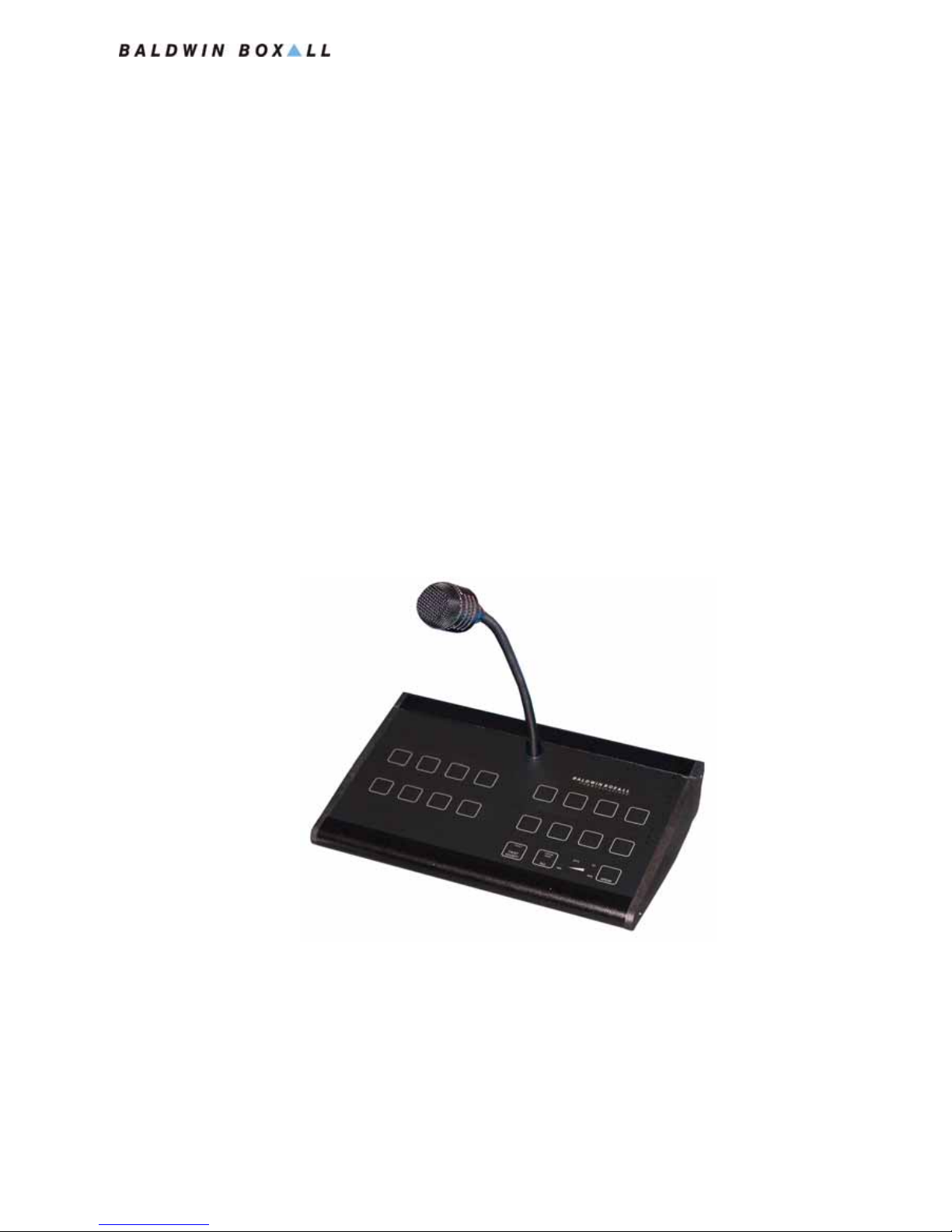
The BDM 400 Microphones Range ________________________2
Microphone Options & Features __________________________2
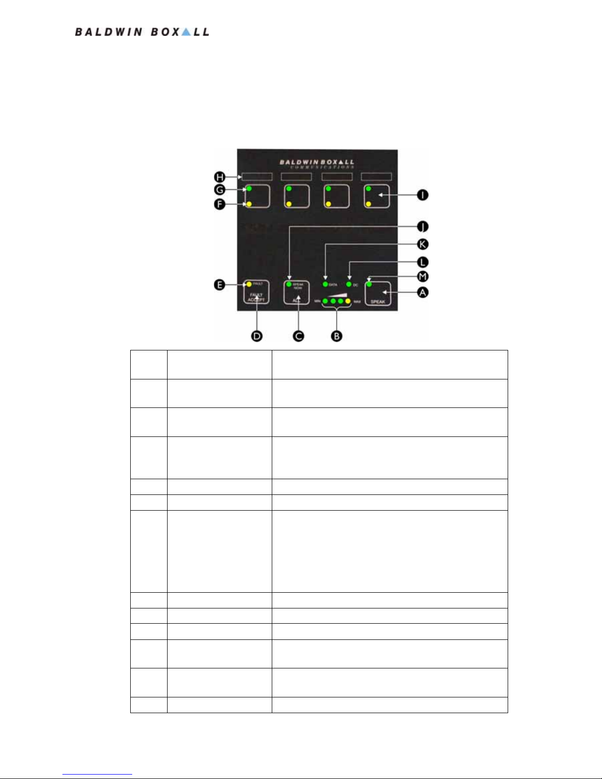
Controls & Indicators __________________________________3
Technical Specification _________________________________4
Installation
BMS8 Termination Box_________________________________5
Hardware Switches and Settings __________________________6
DVA Message Selection option ___________________________7
Processor Bypass “All Call” option ________________________8
Cable Identification____________________________________9
Colour Code for units using Serial Comms- - - - - - - - - - - - - - - - 9
Colour Code for BDM401 in “Parallel” Mode - - - - - - - - - - - - - - 9
Colour Code for Processor Bypass switch - - - - - - - - - - - - - - - - 9
Wall Mounting Option (BDM3WB) _______________________ 10
Installation Instructions - - - - - - - - - - - - - - - - - - - - - - - - 10
Firmware Configuration
Loading “Default” Values_______________________________ 13
Controls & Indicators for Configuration____________________ 14
Entering “Configuration Mode” __________________________ 14
BDM400 Configuration Table ___________________________ 15
Modifying Configuration Settings _________________________ 16
Mic Address & Channel Settings _________________________ 17
Setting Mic Address (using Type 0 protocol) - - - - - - - - - - - - - - 17
Setting Mic Address (using Type 1 protocol) - - - - - - - - - - - - - - 18
Setting Mic Address (Type 2 & 3 protocol) - - - - - - - - - - - - - - - 19

BDM 400 Microphones
Operating Instructions
iv BDM400 Operation Manual issue 10
Setting or cancelling “Auto-cancel of Selected Zones” _________ 20
To Select the Auto-cancel Function - - - - - - - - - - - - - - - - - - 20
To De-select the Auto-cancel Function - - - - - - - - - - - - - - - - 20
Operating Instructions
Controls & Indicators ________________________________ 21
To Make an “All Call” announcement _____________________ 22
Using BDM401 Microphone- - - - - - - - - - - - - - - - - - - - - - 22
Using all other BDM400 Series Microphones - - - - - - - - - - - - - - 22
To Make an Announcement to Selected Zones ______________ 23
Fault Reporting _____________________________________ 23
To Broadcast DVA Messages (only available when fitted) _______ 24
To Broadcast to All Zones - - - - - - - - - - - - - - - - - - - - - - 24
To Broadcast to Selected Zones - - - - - - - - - - - - - - - - - - - 24

BDM 400 Microphones
Operating Instructions
BDM400 Operation Manual issue 10 v
AMENDMENT RECORD
PROPRIETARY NOTICE
All data and information contained within this manual is of a
proprietary nature with the exclusive title to the same held by
Baldwin Boxall Communications Limited. The possession of this
manual and the use of the information is, therefore, restricted
only to those persons duly authorised by Baldwin Boxall
Communications Limited.
Do not reproduce, transcribe, store in a retrieval system or
translate into any language, any part of this manual without the
prior permission of Baldwin Boxall Communications Limited.
In the interest of continual product development, Baldwin Boxall
Communications Limited reserves the right to make changes to
product specification without notice or liability. Use of Baldwin
Boxall Communications Limited products as critical components
in life support systems is not authorised except with express
written approval from Baldwin Boxall Communications Limited.
Change Note
Number
Nature of Amendment Date of
Amendment
2221 Firmware Config updated & made into separate
chapter
March 2009
2400 Issue 9: BDM401 supplied in Parallel Mode by default Oct 2010
2808 Issue 10: Factory Default RS485 Protocol changed to
“Type 2”
March 2014

BDM 400 Microphones
Operating Instructions
vi BDM400 Operation Manual issue 10
SAFETY INFORMATION
Personnel who install, maintain or repair this equipment must
read the safety information below before starting work.
Voltages in excess of 30 Volts RMS or 50 Volts DC are considered
Hazardous and in certain circumstances can be lethal.
If Functional Testing, Maintenance, or Repair is to be completed
with the Mains Power (and/or battery backup) connected then
this should only be undertaken by personnel who are fully aware
of the danger involved and who have taken adequate precautions
and training.
This Manual contains Warnings, Cautions and Notes.
War nings describe potential threats to health or life, e.g.
Cautions describe potential threats to the equipment, e.g.
Notes are statements that are useful to the user in the context of
a particular section of the manual, e.g.
COMMENTS
Comments regarding the content of this manual are welcome and
should be addressed to mail@baldwinboxall.co.uk.
!
WARNING
Before attempting to remove this component, ensure the Mains
Power Supply and Battery Backup have been disconnected.
CAUTION
Notice must be taken of all cautions.
If a Caution is ignored the equipment may be damaged.
CAUTION: ELECTRO-STATIC SENSITIVE DEVICES
Observe the relevant precautions for the protection of Electro-
static Sensitive Devices when handling this equipment.
NOTE: Do not speak into the microphone until the "Speak Now" LED is
illuminated.

BDM 400 Microphones
Operating Instructions
BDM400 Operation Manual issue 10 1
1 Introduction
The BDM 400 range of intelligent Microphones are designed to
provide a wide variety of features to suit any installation.
Figure 1.1 — Typical BDM416 Microphone
The Microphones communicate with the main control system via
an RS485 communications link, and as the only connection
required on each unit is made using a standard RJ45 Network
cable connection (carrying both Audio and Serial Data) system
wiring is considerably reduced.

BDM 400 Microphones
Operating Instructions
2BDM400 Operation Manual issue 10
1.1 THE BDM 400 MICROPHONES RANGE
The range of BDM400 microphones include the following types:
1.2 MICROPHONE OPTIONS & FEATURES
All microphones in the BDM400 range include the following
features as standard:
• Ergonomic design with all buttons and indicators mounted
behind a stylish overlay that allows zone button labels to be
inserted and protected
• The Dynamic Cardioid microphone capsule can be set for
either Monitored or Un-Monitored use during configuration
• “Zone Status” indicators show if a zone is currently selected
or in use
• “Speak Now” indicator to show the user when a pre-
announcement chime has finished
• Simple bar graph display shows the user the current speaking
volume to ensure a clear announcement is made
• “Data” and “DC” indicators to show the unit is functioning
correctly
• A Common Fault indicator is included to show the user if a
fault is evident on the system
• Option to fit fliptop switches to enable DVA Messages to be
broadcast.
Name No. of Zones
BDM401 1
BDM404 4
BDM408 8
BDM416 16
BDM424 24
BDM432 32

BDM 400 Microphones
Operating Instructions
BDM400 Operation Manual issue 10 3
1.3 CONTROLS & INDICATORS
The Front Panel controls and indicators are as follows:
Figure 1.2 — Typical BDM404 Front Panel Controls & Indicators
A"Speak" Button Press button to make an announcement to the selected
zone or zones
BSpeech Level Indicator To ensure clear announcements, the operator should
keep the level below the yellow indicator
C"All Call" Button Press button to speak to All Zones, regardless of
selected zones
D"Fault Accept" Button Press button to accept a fault on the system and silence
the fault buzzer. This button also acts a "Lamp Test" to
check the operation of all indicators
ESystem Fault Indicator Indicates a fault has been detected on the system
FZone Fault Indicator Indicates a fault has been detected on the relevant zone
GZone Status Indicator When a zone is selected, this indicator will flash to
indicate it is selected for the announcement.
If the zone is currently busy, the indicator light
constantly and not flash.
If the zone is busy but also selected, the indicator will
flash intermittently
HZone Label Area Area for Zone labels inserted beneath the overlay
IZone Button Press button to select a zone
J"Speak Now" Indicator Indicates the pre-announcement chime has finished
K"Data" Indicator During normal use, this indicator will flash to show the
microphone is communicating with the system
L"DC" Indicator This indicator shows the microphone is receiving power
from the system
M"Busy" Indicator BDM401 only - indicates the system is busy

BDM 400 Microphones
Operating Instructions
4BDM400 Operation Manual issue 10
1.4 TECHNICAL SPECIFICATION
Audio
Nominal Output Level 700mV
Max Output (limiter operating) 1.5V
Output Impedance 400 Ohms
Frequency Response 250Hz - 10KHz
Power Requirement (24V DC)
BDM401 26mA Standby (30mA Max)
BDM404 & BDM408 35mA Standby (70mA Max)
BDM416 42mA Standby (108mA Max)
BDM424 52mA Standby (150mA Max)
BDM432 62mA Standby (200mA Max)
Serial Data Link
RS485 9600 Baud 8 bit, Even Parity, 1 Stop Bit
Dimensions (W x H x D)
BDM401 / 04 / 8 148mm x 48mm x 177mm
BDM316 275mm x 48mm x 177mm
BDM424 398mm x 48mm x 177mm
BDM432 523mm x 48mm x 177mm

BDM 400 Microphones
Operating Instructions
BDM400 Operation Manual issue 10 5
2 Installation
2.1 BMS8 TERMINATION BOX
The BDM 400 Microphones are designed to allow simple
installation using the minimum of system cabling.
All microphones use a single RJ45 (CAT5 network) connection,
which is usually terminated to a local wall mounted BMS8
Termination box.
Figure 2.1 — Typical BMS8 Termination Box
CAUTION
The BMS8 Termination Box has a standard RJ45 socket to allow
use of a standard CAT5 network cable to connect to the
microphone.
Care must be taken to ensure this socket is not used for any other
equipment since it may be damaged if connected.

BDM 400 Microphones
Operating Instructions
6BDM400 Operation Manual issue 10
2.2 HARDWARE SWITCHES AND SETTINGS
Depending on model, there are up to 6 settings that are available
by removing the right hand side panel of the microphone. These
are shown in Figure 2.2.
Figure 2.2 — Hardware Settings (BDM401 shown)
Ident Marked As... Function
ASTD / MON BDM401 (and Processor Bypass All Call) only - see notes below
Fit link in "STD" position if Monitoring of the Access Line is NOT
required when in "Parallel" mode *
Fit link in "MON" position if Monitoring of the Access Line IS
required when in "Parallel" mode
BS / P BDM401 only - see notes below
Fit link in "P" position to use Parallel Communications *
Fit link in "S" position to use Serial RS485 Communications
CGain / Limiter SW1.1 - Set to ON to increase the gain by 15dB
SW1.2 - Set to "ON" to enable the limiter
DSURV Level Sets the 20KHz surveillance level used to monitor the microphone
capsule
EO/P Level Sets the Output level
FIND Level Sets the Indicator sensitivity (factory preset)
GLK3 Make link if a "Bypass" switch is fitted
HLK2 Make link to connect spare RJ45 conductor to +V IN.
This may be useful in installations with long cable runs.
Can only be used if Bypass switch is not fitted.
NOTE: Monitoring of the Access Line is applicable to the BDM401 when
it is set to "Parallel" Mode or multi-zone BDM microphones with a
Bypass "All Call" switch fitted. Monitoring is acheived by placing a
Zener Diode between the Access Line and 0V.
NOTE: * The Factory Default setting for BDM401 is "P" position for
"Parallel" operation.

BDM 400 Microphones
Operating Instructions
BDM400 Operation Manual issue 10 7
2.3 DVA MESSAGE SELECTION OPTION
The BDM 400 Microphones include an option to broadcast DVA
Messages to either selected or all zones.
The top panel of the microphones have extra cutouts behind the
overlay to allow extra switches to be fitted.
The BDM401, 404 and 408 microphones have three cutouts and
the BDM416 has seven.
It is possible to select one of a range of 8 DVA messages by closing
the relevant DVA selection point to 0V.
Please refer to the following illustration for connection details.
Figure 2.3 — DVA Message Contacts and Switch Connections
NOTE: This is a modification that is normally a factory fitted option.
CAUTION
It is important to ensure switch terminals do not short out on the
chassis due to the limited height within the body of the
microphone.
If required, please contact our Technical Sales department for
details of suitable switches.
Note: If using Type 0 RS485 protocol it is only possible to select DVA
Messages 1-7.
With Type 1, 2 or 3 RS485 protocol the range of the DVA messages can
be set during configuration. Refer to Section 3.4 for details.

BDM 400 Microphones
Operating Instructions
8BDM400 Operation Manual issue 10
2.4 PROCESSOR BYPASS “ALL CALL” OPTION
It is possible to add an extra hard wired “All Call” processor
bypass access switch to the BDM microphones to enable
broadcasts in the unlikely event that the router suffers from a
processor fault or RS485 network failure.
The bypass switch should be connected between JP8 & JP9, a
solder bridge should be made across LK3, and LK4 should be
carefully drilled out as shown in Figure 2.4.
Figure 2.4 — Connections required for Processor Bypass “All Call” switch
NOTE: This is a modification that is normally a factory fitted option.
NOTE: The BDM401 in Parallel mode can access an "All Call" bypass
input without adding an extra switch.
NOTE: The BDM microphone must be connected to the correct input on
the BVRD2M for the processor bypass to operate.
NOTE: If the Access line is to be monitored ensure JP4 is set to "MON".
For further information refer to Figure 2.2.

BDM 400 Microphones
Operating Instructions
BDM400 Operation Manual issue 10 9
2.5 CABLE IDENTIFICATION
2.5.1 Colour Code for units using Serial Comms
2.5.2 Colour Code for BDM401 in “Parallel” Mode
2.5.3 Colour Code for Processor Bypass switch
The colour code for multi zone Microphones with a Bypass switch
fitted are as shown in Section 2.5.1.
The Bypass Access is on Pin 7 (Brown / White).
Function Pin # Cable Colour
+V DC 1Orange / White
0V 2 & 8 Orange & Brown
Data "A" 3Green / White
Audio 4 Blue
Audio 5 Blue / White
Data "B" 6Green
Spare 7Brown / White (Not used by default)
NOTE: The table above is correct for all types of microphone except when
the BDM401 is used in "Parallel" Mode without RS485 comms.
Function Pin # Cable Colour
+V DC 1Orange / White
0V 2 & 8 Orange & Brown
"PTT" 3Green / White (Closes to 0v when PTT is pressed)
Audio 4 Blue
Audio 5 Blue / White
"Busy" 6 Green (Close to 0V to illuminate "Busy" LED)
Spare 7Brown / White (Not used by default)
NOTE: The BDM401 Factory Default setting is "Parallel".

BDM 400 Microphones
Operating Instructions
10 BDM400 Operation Manual issue 10
2.6 WALL MOUNTING OPTION (BDM3WB)
The Wall Mounting option (product code BDM3WB) allows any
of the BDM 400 Microphones to be wall mounted.
The BDM3WB is separate back plate that is secured to the wall.
The overall dimensions and the positions of the mounting holes of
the back plate are shown in Figure 2.5
Figure 2.5 — Mounting hole positions on BDM3WB
2.6.1 Installation Instructions
1. Mount the back plate on the wall.
2. Remove one of the side panels of the microphone.
3. Slide the microphone over the back plate.
Ensure both the upper and lower raised edges of the back
plate slide securely into the corresponding mounting slots in
the extrusion of the base of the unit.
These slots are shown in Figure 2.6.

BDM 400 Microphones
Operating Instructions
BDM400 Operation Manual issue 10 11
Figure 2.6 — Mounting slots for Wall Mounting bracket
4. Refit the side panel on the microphone.
The side panel secures the microphone onto the back plate.
For wall mounting larger microphones (such as the BDM416,
BDM424 or BDM432) two mounting plates can be placed side by
side.

BDM 400 Microphones
Operating Instructions
12 BDM400 Operation Manual issue 10

BDM 400 Microphones
Operating Instructions
BDM400 Operation Manual issue 10 13
3 Firmware Configuration
It is necessary to configure the microphone prior to use.
This configuration includes setting system specific options such as
enabling the unit to communicate with the system, enabling
monitoring of the microphone capsule, and setting the delay
before the “Speak Now” indicator illuminates.
3.1 LOADING “DEFAULT” VALUES
To load the default settings (shown in Table 3.1) the following
procedure should be used:
1. Remove the RJ45 lead,
2. Press and hold the “Speak” button,
3. Re-connect the RJ45 lead,
4. Release the “Speak” button after 3 seconds.
Default configuration values will then be loaded into the unit.
Note: Before the Microphone can be used the RS485 button allocation
data must be downloaded from the BVRD2M.
Press and hold the "FAULT ACCEPT" button for 2 seconds to load the
current button allocation data.
It is necessary to download this data after entering Configuration Mode.

BDM 400 Microphones
Operating Instructions
14 BDM400 Operation Manual issue 10
3.2 CONTROLS & INDICATORS FOR
CONFIGURATION
When in Configuration Mode, the functions of the front panel
indicators and controls are as shown in Figure 3.1.
Figure 3.1 — Controls when in Configuration Mode
3.3 ENTERING “CONFIGURATION MODE”
1. Disconnect power from the unit by removing the RJ45 cable.
2. Press and hold the “Fault Accept” button (“D” in Figure 3.1).
3. Connect the RJ45 cable.
4. Release the “Fault Accept” button when the “Busy” indicator
(item “B” in Figure 3.1) flashes.
5. The Busy indicator should now flash once.
This indicates the unit is in Position 1 within the
Configuration Table, and the “Speak Now” LED will also flash
to indicate the current setting of the “Speak Now Delay”
(which is position 1 in the configuration table).
6. The unit is now in Configuration Mode.
Original Function Function in "Configuration" Mode
A"Speak Now" LED Flashes to show the current setting of the value or
function
B"Busy" LED Flashes to show the current location in the
Configuration Table
C"Speak" Button Press to change the setting of the value or function
D"Fault Accept"
Button
Press to step on to the next location in the internal
Configuration Table
NOTE: The Busy Indicator is only identified on the BDM401.
On other models the Indicator is present but has no ident on the panel.
Table of contents
Other Baldwin Boxall Microphone manuals

Baldwin Boxall
Baldwin Boxall BVRAMB User manual

Baldwin Boxall
Baldwin Boxall BFM 400 User manual

Baldwin Boxall
Baldwin Boxall BVRDTSM User manual

Baldwin Boxall
Baldwin Boxall BDM201 User manual

Baldwin Boxall
Baldwin Boxall BDM 208 User manual

Baldwin Boxall
Baldwin Boxall BVRDTSM Operating and maintenance manual

Baldwin Boxall
Baldwin Boxall BVR16M User manual

Baldwin Boxall
Baldwin Boxall BDM 204 User manual

Baldwin Boxall
Baldwin Boxall BVRD series User manual

Baldwin Boxall
Baldwin Boxall BDM300 User manual