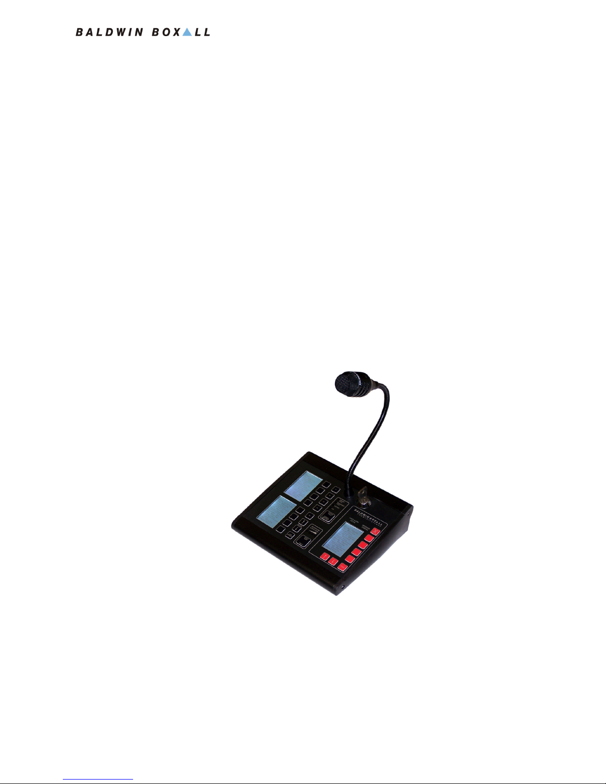
BVRD Series Microphones
Installation Instructions
vi BVRD Series Microphones issue 5
SAFETY INFORMATION
Personnel who install, maintain or repair this equipment must
read the safety information below before starting work.
Voltages in excess of 30 Volts RMS or 50 Volts DC are considered
Hazardous and in certain circumstances can be lethal.
If Functional Testing, Maintenance, or Repair is to be completed
with the Mains Power (and/or battery backup) connected then
this should only be undertaken by personnel who are fully aware
of the danger involved and who have taken adequate precautions
and training.
This Manual contains Warnings, Cautions and Notes.
War nings describe potential threats to health or life, e.g.
Cautions describe potential threats to the equipment, e.g.
Notes are statements that are useful to the user in the context of
a particular section of the manual, e.g.
COMMENTS
Comments regarding the content of this manual are welcome and
should be addressed to mail@baldwinboxall.co.uk.
!
WARNING
Before attempting to remove this component, ensure the Mains
Power Supply and Battery Backup have been disconnected.
CAUTION
Notice must be taken of all cautions.
If a Caution is ignored the equipment may be damaged.
CAUTION: ELECTRO-STATIC SENSITIVE DEVICES
Observe the relevant precautions for the protection of Electro-
static Sensitive Devices when handling this equipment.
NOTE: Do not speak into the microphone until the "Speak Now" LED is
illuminated.