Balluff BIS Z-GW-001-DNT User manual

BIS Z-GW-001-DNT
Subnet16™ DeviceNet Gateway
INSTALLATION GUIDE
This document provides instructions and information designed
to assist users in the hardware setup of the Subnet16™
DeviceNet Gateway. For configuration details see the Gateway
Manual.
The BIS Z-GW-001-DNT is designed to connect RFID
applications to a DeviceNet network. The Gateway is a
DeviceNet Slave node which connects to a DeviceNet Master
(Host PC or PLC) through a DeviceNet-compatible network
cable and is also powered through this network.
It supports Subnet16™ Multidrop bus architecture, a
subnetwork of up to sixteen Balluff RFID processor stations,
through an RS485 interface connection. The Subnet16™
network is powered separately.
A USB port is used for establishing a direct serial connection
with a host computer for the purpose of configuring the
Gateway through the Dashboard Configuration Tool program.
TECHNICAL DATA
ELECTRICAL FEATURES
Power Supply 12 - 30 Vdc
DC Input Current max. 200 mA - 100 mA
Communication Interfaces:
Host
RFID Multidrop Readers
Configuration
DeviceNet
Subnet16™
(uses RS485 physical layer)
USB 2.0
Baud Rate (kbps) 125 (default), 250, 500
ENVIRONMENTAL FEATURES
Operating Temperature -20°to +50 °C
(-4°to +122 °F)
Storage Temperature -20°to +70 °C
(-4°to +158 °F)
Humidity max. 90% non condensing
Vibration Resistance
EN 60068-2-6 14 mm @ 2 to 10 Hz;
1.5 mm @ 13 to 55 Hz;
2 g @ 70 to 200 Hz;
2 hours on each axis
Shock Resistance
EN 60068-2-27 30 g; 11 ms;
3 shocks on each axis
Protection Class
EN 60529 IP30
PHYSICAL FEATURES
Dimensions 112 x 107 x 32 mm
(4.4 x 4.2 x 1.3 in)
Weight 256 g (9 oz)
USER INTERFACE
LED Indicators Power On, Subnet16™ Bus,
DeviceNet,
Configuration Error
GENERAL VIEW
LED INDICATORS
green POWER
The POWER LED is ON whenever
power is applied to the Gateway
through the DeviceNet connector.
amber Subnet16™
BUS
The BUS LED will flash ON and OFF to
indicate that data is being transmitted
between the Gateway and one or more
RFID controllers on the Subnet16™
network.
green/red DEVICENET
SOLID GREEN: Gateway is
operational, online AND a connection is
established. FLASHING GREEN:
Gateway is operational and online, but
with no established I/O connections
(idle on the network) or Gateway is
online and needs commissioning.
FLASHING RED: Recoverable fault
detected and/or the Gateway’s I/O
connection timed out.
SOLID RED: Unrecoverable fault
detected (for example, a duplicate node
address was encountered rendering
Gateway unable to communicate).
red ERROR
The Error LED is solid red when a
Gateway configuration error has
occurred, i.e. an invalid or unrecognized
command. This LED will be cleared
when a valid command is sent.
CONNECTIVITY
DeviceNet
M12 5-pin Male Connector
(DeviceNet and Gateway Power Supply)
USB
Configuration
USB Type B Female Connector
1
2
3
4
Subnet16™
M12 5-pin Female Connector
(Data and Subnet16™ Power Supply)
Typical Layout
See the Gateway Manual for a complete list of accessories including alternative cables and connectors.
HARDWARE REQUIREMENTS
The following components are required for a complete Subnet16™
RFID system:
•
One Subnet16™ DeviceNet Gateway Interface Module
•
One ControlLogix PLC or other DeviceNet-capable host
•
One to 16 processors (
BIS M-41x, BIS M-62x or BIS U-62x-
Series Processors - RS485 models)
•
Adequate length cabling, connectors and terminators
•
A suitable power supply capable of providing sufficient power
to the Gateway via DeviceNet network cabling
•
A suitable power supply capable of providing sufficient power
to the RFID controllers via Subnet16™ network cabling
•
Balluff RFID data carrier or labels: BIS M-1xx or BIS U-1xx
INSTALLATION GUIDELINES
•
Do not route cables near unshielded cables or near wiring carrying
high voltage or high current. Cross cables at perpendicular
intersections and avoid routing cables near motors and solenoids.
•
Review the power requirements of your RFID network and provide
a suitable power supply.
•
Avoid mounting the controller near sources of EMI (electro-
magnetic interference) or near devices that generate high ESD
(electro-static discharge) levels. Always use adequate ESD
prevention measures to dissipate potentially high voltages.
•
If electrical interference is encountered (as indicated by a
significant reduction in read/write performance), relocate the
controller to an area free from potential sources of interference.
•
Perform a test phase by constructing a small scale, independent
network that includes only the essential devices required to test
your RFID application (use Balluff approved Subnet16™ cables
and accessories).
INSTALLATION
The numbered steps in the following procedure are also indicated in
the Subnet16™ network example layout shown in the figure.
1. Preliminary Notes: Read this document in its entirety and note
the
Installation Guidelines
above.
2. Mounting: Mount the Gateway to your chosen location using two
M5 (#10) screws, lock washers and nuts. The Gateway may be
mounted in any orientation, but should be aligned in such a
manner that the LED indicators can be seen during operation.
3. Gateway Connection: Attach one end of a 5-pin, male-to-male,
M12, ThinNet drop cable (
P/N: BCC0ET4
) to the 5-pin, female,
M12 connector on the Gateway. Connect the other end of this 5-
pin, male-to-male, M12, ThinNet drop cable to the 5-pin, female,
M12 connector on a
ThinNet to ThinNet Drop-T Connector
(as
per your network and RFID application requirements).
4. Trunk Wiring: Attach one end of a male-to-female trunk cable to
each mating connector on the Drop-T Connector. Continue
connecting trunk cables and Drop-T connectors as needed.
Note: trunk length should not exceed 300 m for ThickNet and 20 m
for ThinNet.
5. Termination Resistors: For ThinNet Networks: Connect a
Terminating Resistor (
P/N: BCC9MR,
male)
to the first and last
Drop-T Connector on the trunk line.
(over)
PIN 3:
V-
PIN 2:
V+
PIN 5:
CAN_L
PIN 4:
CAN_H
PIN 1:
SHIELD
PIN 5:
TX/RX-
PIN 1:
SIGNAL
GND
PIN 4:
TX/RX+
PIN 3:
GND
PIN 2:
VDC
VDC
GND
D
-
D+
BCC07WR
BCC0E04
BCC07WR
BCC0E04 BCC0E04 BCC0E04
BCC09MR
BCC0E04
Gateway
to DeviceNet
Master (Host)
+ Gateway Power to Subnet16™
Power Supply
Vdc
GND
BCC09MR
BCC06ZF
BIS U-30X
BIS U
-
620
-
067
-
1X1
-
04
-
S92
BIS U-30X BIS U-30X BIS U-30X
BCC07WR
BCC07WR
BCC07WR
BCC07WR
BCC0ET4
BCC0E04
BCC0E04
BCC0E04
BCC0E04
BIS U
-
620
-
067
-
1X1
-
04
-
S92
BIS U
-
620
-
067
-
1X1
-
04
-
S92
BIS
U
-
620
-
067
-
1X1
-
04
-
S92
4
3
4
4
4
5
5
6
6
6
6
8
7

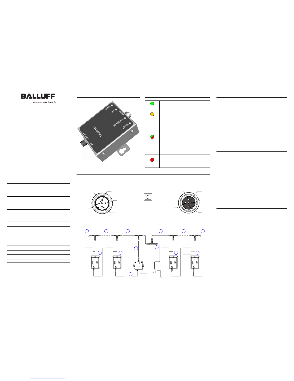
6. RFID Controller Connection: Connect the male end of a 5-pin,
male-to-female, ThinNet drop cable to the female end on your
Drop-T connector(s). Attach the remaining female end of the
ThinNet drop cable to the 5-pin, male, M12 connector on a
BIS U
,
BIS M-6xx
or
BIS M-41x (RS485 models)
. Repeat
Step 5
for
each RFID controller you plan to install.
Note: maximum drop cable length is 2 m.
Subnet16™ Power Supply Wiring: For ThinNet Networks: Using a 5-
pin, female, M12, ThinNet connector (
P/N: BCC06ZF
), make a power
cable and connect it to your power supply (SHIELD wire connected to
Earth). Attach the female, ThinNet end to the 5-pin, male, ThinNet end
on a Drop-T connector (
P/N: BCC07WR).
7. Gateway Power and Host Connection: Connect the Gateway to
the DeviceNet network via a DeviceNet-compatible interface
cable. The Gateway must be powered through pins V+ and V- of
the DeviceNet connector.
8. Power On: Turn both power supplies ON. The POWER LED on
the Gateway will remain lit while power is applied to the unit
through the DeviceNet connector.
9. Automatically Configure Subset16™ Node IDs: At this point all
controllers are powered and should have Node IDs set to 00, (all
controller Node LEDs = OFF), and Subnet16™ baudrate = 9600
(factory defaults).
a. Place the RFID Controller Configuration Tag in front of an
RFID Controller (the controller's RF Activity LED blinks once
indicating the tag has been read), and wait for the Gateway to
assign a valid Node ID to it. The controller's Node LEDs now
indicate a valid Node ID. Remove the Configuration Tag from
the controller.
b. Repeat this step for each node in the Subnet16™ network
(one controller at a time). The first is Node ID 1, then 2 and so
on up to 16 (binary).
The Subnet16™ network is now configured with the default values and
can communicate with the DeviceNet Gateway which in turn
communicates with the DeviceNet Master.
BIS Z-GW-001-DNT DEVICENET FACTORY DEFAULTS:
Node Address: 63; Baud Rate: 125 kbps
For further information or for application specific configuration using
the Dashboard Configuration Tool program, see the Gateway Manual.
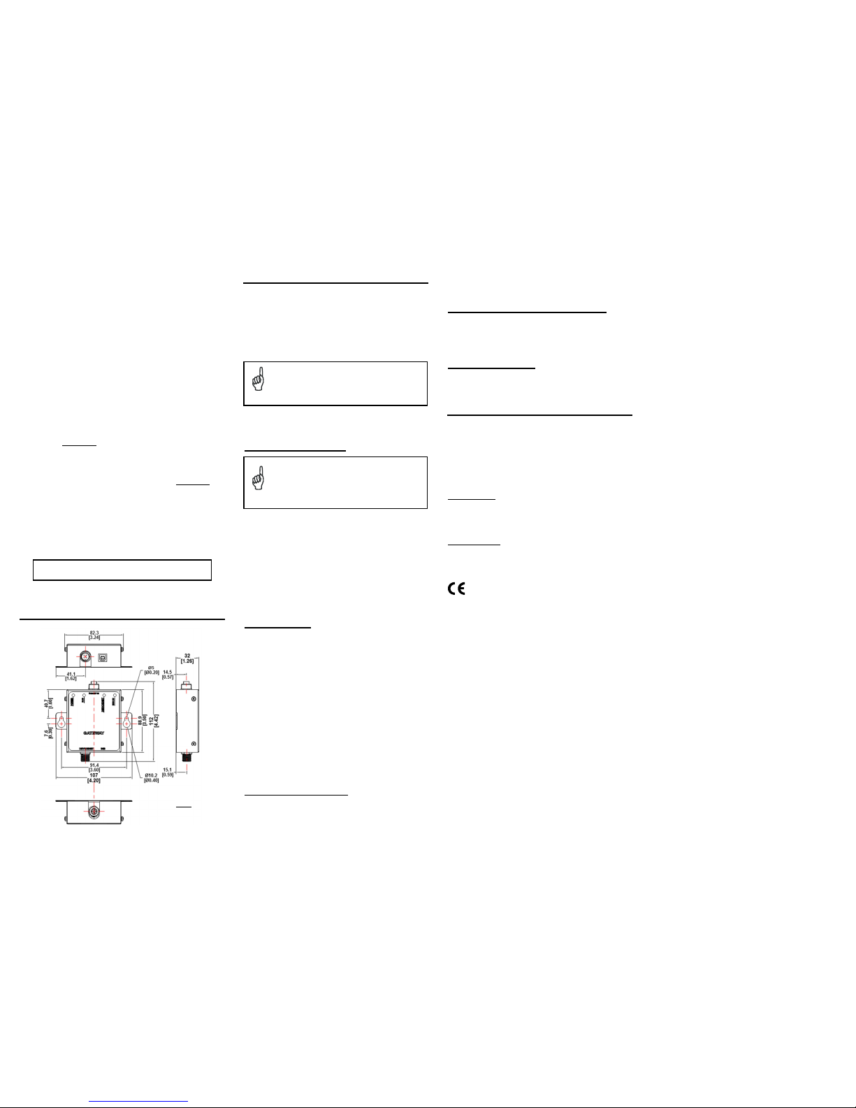
DIMENSIONS
POWER REQUIREMENTS
The DeviceNet Gateway requires an electrical supply voltage of
12 to 30 Vdc. It is powered through the DeviceNet network
connector.
In addition, each RFID controller connected to the Gateway via
the Subnet16™ network will also require power. This network is
powered separately. Use a regulated power supply that is
capable of delivering the requirements listed in the Technical
Features.
NOTE
Power is applied directly to the Subnet16™ Network
trunk and distributed through drop cables to the RFID
controllers. By positioning the power supply near the
middle of the network, you can limit voltage drop at the
ends, (see example layouts).
The following information is provided to assist you in
determining the power requirements of your RFID application.
System Current Consumption
NOTE
The current consumption values of each product are
given in the Technical Features paragraph of the relative
Installation manual and refer to the min and max input
voltage range. These values already include an
adequate safety margin. The consumption values given
in the following examples have been interpolated for an
input voltage of 24 Vdc.
Max Gateway Current: 200 mA @ 12 Vdc (133 mA @ 24 Vdc).
Max Processor Current: 366 mA @ 24 Vdc for BIS M-6xx-Series, 87
mA @ 24 Vdc for BIS M-41X-Series, etc. (refer to Processor ’s spec).
Calculating Subnet16™ System Current Consumption:
Subnet16™ System Current Consumption = (Max Controller
Current x Number of Controllers)
Example
A Subnet16™ network powered at 24 Vdc is composed of a BIS Z-GW-
001-DNT connecting eight BIS M-41X-485 Processor s.
Subnet16™ System Current Consumption = (0.087 A X 8)] = 0.696 A
Cable Voltage Drop
In addition, each RFID controller on the Subnet will experience a certain
amount of voltage drop dependingon the length of the cable.
Cable Resistance per Meter
•ThinNet = 0.058 ohms per meter per wire
•ThickNet = 0.0105 ohms per meter per wire
Calculating Voltage Drop
Voltage Drop = (Max Controller Current x Number of Controllers) x
(Cable Resistance per Meter perWire
1
x Cable length
in Meters)
Example
A Subnet16™ network is composed of a BIS Z-GW-001-DNT
connecting eight BIS M-41X-485 Processors (87 mA each @ 24 Vdc). A
total of 20 meters of ThinNet cables are used to connect the devices,
which have Cable Resistance = 0.058 Ohms per meter per wire. The
network power is 24 Vdc.
2
Voltage Drop = (0.087 A x 8 controllers) x [(0.058 x 2) x 20 meters] =
1.61 Vdc
24 Vdc - 1.61 = 22.39 Vdc at controller number 8
1
The resistance calculation must include both wires (Vdc and GND).
2
This example assumes the power supply is placed at the end of the
network, therefore controller #8 is the worst case. By placing the
power supply in the middle of the network the voltage drop at the
ends is reduced.
It is recommended that the voltage drop calculation be conducted on
the RFID controller that is farthest from the Gateway, as it will
experience the greatest voltage drop.
Max Supported Trunk and Drop Cable Lengths
•
ThickNet trunk length up to 300 m.
•
ThinNet trunk length up to 20 m.
•
ThinNet drop cable length up to 2 m.
Current Rating for Cables
The maximum current rating for the Subnet16™ network using
Balluff cables and accessories (BCCxxxx), is 4.0 A.
COMPLIANCE
This product is intended to be installed by Qualified
Personnel only.
This product must not be used in explosive environments.
See the Subnet16™ Gateway Manual for the Declaration of
Conformity.
Power Supply
This device is intended to be supplied by a UL Listed or CSA
Certified Power Unit with «Class 2» or LPS power source.
CE Compliance
Warning: This is a Class A product. In a domestic environment
this product may cause radio interference in which case the
user may be required to take adequate measures.
mm
in
Nr. 89
0
413
E
.
Edition 130
5
; Subject to modification.
Table of contents
Other Balluff Gateway manuals
Popular Gateway manuals by other brands

Garmin
Garmin Flight Stream 110/210 installation manual

Quasar
Quasar SmartCell 212 installation manual

Amit
Amit SDE852-00001 user manual

Mennekes
Mennekes eMobility-Gateway Professional+ OPERATING AND INSTALLATION Manual

AudioCodes
AudioCodes Mediant 1000 MSBG Installation and configuration manual

Navoto
Navoto Hessler Safety Instructions & Quick Start User Guide