Content
1Notes to the user 3
1.1 Structure of the guide 3
1.2Typographical conventions 3
Enumerations 3
Actions 3
Syntax 3
Cross-references 3
1.3 Symbols 3
1.4 Abbreviations 3
1.5 Deviating views 3
2Safety 4
2.1 Intended use 4
2.2 Installation and startup 4
2.3 General safety instructions 4
2.4 Resistance to aggressive substances 4
Hazardous voltage 4
3Getting Started 5
3.1 Overview BNI IOL-802-000-Z036 5
3.2 Overview BNI IOL-802-000-Z037 6
3.3 Mechanical connection 7
3.4 Electrical connection 7
3.5 Function ground 7
3.6 IO-Link connection 7
Smart Light connection 7
Module versions 7
3.7 Short description of the functionality 8
3.8 Segment mode 8
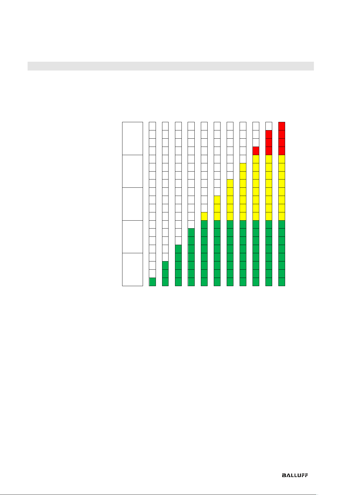
3.9 Level mode 8
3.10 Runlight mode 11
3.11 Flexible mode 12
3.12 Synchronisation 12
4IO-Link Interface 13
4.1 IO-Link Data 13
4.2 Process data / Output data 13
BNI IOL-802-000-Z03x, Segment Mode 13
Bit definitions in segment mode 13
BNI IOL-802-000-Z03x, Level Mode 14
Bit definitions in level mode 14
BNI IOL-802-000-Z03x, Runlight Mode 15
Bit definitions in runlight mode 15
BNI IOL-802-000-Z03x, Flexible Mode 16
Bit definitions in flexible mode 16
4.3 Parameter data/ Request data 17
Mode 40hex 20
Number of segments 41hex 20
Level type 42hex 20
Level resolution 43hex 20
Level mode segment x color 44hex 45hex 46hex 47hex 48hex 20
Level mode limit x-y 49hex 4Ahex 4Bhex 4Chex 21
Runlight mode, background color 4Dhex 22
Runlight mode, running color 4Ehex 22
Runlight mode, number of running segments 4Fhex 22
Supply monitoring 50hex 23
Brightness 51hex 23
Blinking frequency / Runlight speed 52hex 24
Blinking mode 53hex 24