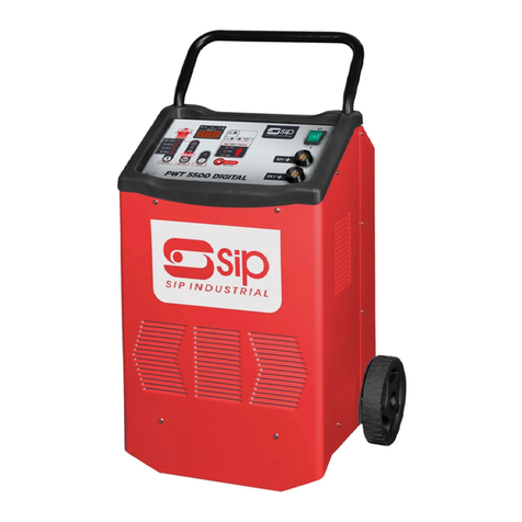
SIP startmaster P440 User manual

20
FOR HELP OR ADVISE ON THIS PRODUCT PLEASE CONTACT YOUR DISTRIBUTOR,
OR SIP DIRECTLY ON:
TEL: 01509500400
EMAIL: sales@sip-group.com or technical@sip-group.com
www.sip-group.com
Please dispose of packaging for the product in a responsible
manner. It is suitable for recycling. Help to protect the
environment, take the packaging to the local amenity tip
and place into the appropriate recycling bin.
Never dispose of electrical equipment or batteries in with
your domestic waste. If your supplier offers a disposal facili-
ty please use it or alternatively use a recognised re-cycling
agent. This will allow the recycling of raw materials and help
protect the environment.
Ref: 060912
1
Startmaster
P440 & P560
Starter / charger
Please read and fully understand the instructions in
this manual before operation. Keep this manual
safe for future reference
05533 & 05535

2
19
Declaration of Conformity
We
SIP (Industrial Products) Ltd
Gelders Hall Road
Shepshed
Loughborough
Leicestershire
LE12 9NH
England
As the manufacturer's authorised representative within the EC
declare that the
Starmaster P440 -SIP Pt. No. 05533
Starmaster P560 -SIP Pt. No. 05535
Conforms to the requirements of the following directive(s), as indicated.
2006/95/EC Low Voltage Directive
2004/108/EC EMC Directive
2002/95/EC ROHS Directive
And the following harmonised standard(s)
EN ISO 12100-2/A1:2009
EN 61029-1:2009
EN 55014-1:2006
EN 55014-2/A1:2008
EN 61000-3-2:2006
EN 61000-3-3:2008
Signed: …………………………………...
Mr P. Ippaso - Director - SIP (Industrial Products) Ltd
Date: 21/05/2010.
DECLARATION OF CONFORMITY

18
PARTS LIST - STARTMASTER P560
Ref. No. Description SIP Part No.
1 Handle PW02-00082
2 Cover PW02-00085
3 Chassis PW02-00091
4 Thermostat (rectifier) PW02-00027
5 Rectifier PMS40/125 PW02-00035
6 On/Off switch PW02-00022
7 High/Low switch 16a PW02-00021
8 Front frame (plastic) PW02-00097
9 Ammeter 20A/start PW02-00016
10 Fuse holder PW02-00010
11 Cable gland PW02-00079
12 Fuse 120a PW02-00005
13 Cover for fuse holder PW02-00011
14 Red cable PW02-00058
15 Red/Black clamps PW02-00072
16 Black cable PW02-00066
17 Mains lead PW02-00113
18 Terminal assy complete PW02-00104
19 Front panel PW02-00093
20 Transformer PW02-00049
21 Thermostat (transformer) PW02-00028
3
CONTENTS
Page No. Description
4 Safety instructions
7 Guarantee
7 Electrical connections
9 Technical specifications
10 Getting To Know Your Starter / Charger
11 Operating Instructions
13 Wiring Diagrams
14 Troubleshooting
15 Parts list & Exploded Diagram Startmaster P440
17 Parts list & Exploded Diagram Startmaster P560
19 Declaration on conformity

4
SAFETY INSTRUCTIONS
IMPORTANT: Please read the following instructions carefully, failure to do so could
lead to serious personal injury and / or damage to the Starter / charger and any-
thing connected to it.
When using your starter / charger, basic safety precautions should always be followed
to reduce the risk of fire, electric shock, personal injury and / or damage to the starter /
charger. Read all these instructions before operating the charger and save this user
manual for future reference.
SIP recommends that this charger should not be modified or used for any application
other than that for which it was designed. If you are unsure of its relative applications
do not hesitate to contact us and we will be more than happy to advise you.
These starter / chargers are designed for the charging of lead-acid batteries, and for
starting vehicles with lead acid batteries fitted. They should not be used as a DC pow-
er source, or used to recharge non-rechargeable batteries. To do so may cause fire,
electric shock, etc.
They are designed to be powered from a 230v ~ 50 / 60Hz supply, which is reliably
connected to the buildings ground (earth) point.
If the supply cable needs to be extended, ensure the cross-sectional area of the wire
in the extension lead is of a sufficient size for the supply of current over the distance
required.
If the charger is interrupted or damaged due to heavy impact etc., the battery should
be taken off charge immediately.
Do not dismantle the charger - If repairs are required, they should be performed by a
suitably qualified person. Incorrect reassembly may result in a fire hazard and / or
electric shock.
Always disconnect the charger from any connected battery and the mains supply
prior to cleaning the casing or changing fuses etc.
When connecting the charger to a vehicle’s battery. Always connect the battery termi-
nal not connected to the chassis first. The other connection is to be made to the
chassis as far away as practical from the battery and fuel line (a spark can be gener-
ated when connecting the second clip which can ignite battery or fuel gases). The
starter / charger is then to be connected to the mains supply. Once charging is com-
plete, disconnect the starter / charger from mains supply first, and then remove the
chassis connection followed by the battery connection.
17
EXPLODED DIAGRAM - STARTMASTER P560

16
PARTS LIST - STARTMASTER P440
Ref. No. Description SIP Part No.
1 Handle PW02-00082
2 Cover PW02-00085
3 Chassis PW02-00091
4 Rectifier PW02-00033
5 On/Off switch PW02-00022
6 High/Low switch 16a PW02-00021
7 Front frame (plastic) PW02-00097
8 Ammeter 20A/start PW02-00016
9 Fuse holder PW02-00010
10 Cable gland PW02-00079
11 Fuse 100a PW02-00004
12 Cover for fuse holder PW02-00011
13 Red cable PW02-00056
14 Red/Black clamps PW02-00071
15 Black cable PW02-00064
16 Mains lead PW02-00111
17 Terminal assy complete PW02-00104
18 Front panel PW02-00093
19 Transformer PW02-00047
5
SAFETY INSTRUCTIONS….cont
During charging, batteries give off some hydrogen and oxygen creating a highly ex-
plosive mix. Ensure adequate ventilation exists and avoid sparks, smoking, etc.
During battery maintenance ensure adequate clean water is available in the event of
an acid spill. The liquid inside batteries is highly corrosive therefore ensure that it is not
allowed to make contact with the skin (especially eyes). In the event of contact, flush
the area with clean water and immediately consult a doctor.
Lead-acid batteries store a large amount of energy. Short-circuiting the battery or
charger terminals will cause the battery to try and release this energy immediately,
which can result in fire or personal injury. Prevent any metal object (or other conduc-
tive material) from touching the + and –terminals of the charger or battery at the
same time.
KNOW YOUR STARTER / CHARGER: Read and understand the owner's manual and la-
bels affixed to the charger. Learn its applications and limitations, as well as the poten-
tial hazards specific to it.
DO NOT USE THE STARTER / CHARGER IN DANGEROUS ENVIRONMENTS: Do not use your
Starter / charger in damp or wet locations, or expose it to rain. Always provide ade-
quate space around the starter / charger.
KEEP CHILDREN AND UNTRAINED PERSONNEL AWAY FROM THE WORK AREA: All visitors
should be kept at a safe distance from the work area.
STAY ALERT: Always watch what you are doing and use common sense.
DISCONNECT THE STARTER / CHARGER FROM THE MAINS SUPPLY: When not in use.
DO NOT ABUSE THE MAINS LEAD: Never pull the mains lead it to remove the plug from
the mains socket. Keep the mains lead away from heat, oil and sharp edges. If the
mains lead is damaged, it must be replaced by the manufacturer or its service agent
or a similarly qualified person in order to avoid unwanted hazards.
HAVE YOUR STARTER / CHARGER REPAIRED BY A QUALIFIED PERSON: The starter / charger
is in accordance with the relevant safety requirements. Repairs should only be carried
out by qualified persons using original spare parts, otherwise this may result in consid-
erable danger to the user and void the warranty.
DANGER! Check that the starter / charger is in sound condition and good working
order. Take immediate action to repair or replace damaged parts.
USE RECOMMENDED PARTS ONLY - Unapproved parts may be dangerous and will
invalidate the warranty.
WARNING! Only operate on a level and stable surface.
WARNING! Do not allow untrained persons to operate the charger and do not oper-
ate the machine without all covers etc. correctly fitted.
WARNING! RISK OF ELECTRIC SHOCK. Do not expose the starter / charger to water
spray, rain, dripping water or moisture of any kind.
Do not move or handle the charger when it is running.
Do not leave the charger unattended for long periods when in use. Switch the

6
charger off and unplug from the mains supply before leaving the work area.
Ensure that the starter / charger is correctly turned off when not in use and store in a
safe, dry area, out of reach of children.
Do not unplug the starter / charger to switch it off - always use the on/off switch.
Keep all combustible materials away from this starter / charger.
ALWAYS locate the starter / charger in an area of good ventilation.
ALWAYS keep children and animals away from charger.
Never stand on the charger.
DO NOT dismantle or tamper with the starter / charger, as this may be dangerous
and will invalidate the warranty.
If a problem with the starter / charger is experienced, or if the mains lead or plug be-
come damaged, contact your distributor for repair.
If the charger is used in a place of work all rules and laws etc. relating to the use of
portable electrical appliances should be followed.
WARNING: Risk of Electric Shock!
Use only the electrical power (voltage and frequency) specified on the model plate
of the starter / charger. If in doubt contact the manufacturer.
Use only a three-prong, grounded mains supply socket.
ALWAYS unplug the starter / charger when not in use.
SAFETY INSTRUCTIONS...cont
Safety Symbols Used Throughout This Manual.
Danger / Caution: Indicates risk of personal injury and/or the possibility of
damage.
Warning: Risk of electrical injury or damage!
Note: Supplementary information.
CAUTION: The warnings and cautions mentioned in this user manual can not cover
all possible conditions and situations that may occur. It must be understood by the
operator that common sense and caution are factors which cannot be built into
this product, but must be applied.
15
EXPLODED DIAGRAM - STARTMASTER P440

14
TROUBLE SHOOTING
Fault Possible cause Solution
Bad contact of power socket Repair or replace socket
Initial voltage is too low Change battery
No charging current + and - polarity terminals of battery
are oxidised or dirty Clean terminals
Battery is damaged Replace battery
Fuse blown Replace fuse
Overload popped out Reset overload
+ and - polarity terminals of battery
are oxidised or dirty Clean terminals
Low charging current Battery not accepting charge Replace battery
Battery is charged fully Measure specific gravity
Excessive transformer
noise Unstable position Change position for
proper placement
7
GUARANTEE
Guarantee:
These SIP starter / chargers are covered by a 12 month parts and labour warranty cov-
ering failure due to manufacturers defects. This does not cover failure due to misuse or
operating the charger outside the scope of this manual - any claims deemed to be
outside the scope of the warranty may be subject to charges Including, but not lim-
ited to parts, labour and carriage costs. Consumable items such as fuses are not cov-
ered by the warranty.
In the unlikely event of warranty claims, contact your distributor as soon as possible.
Proof of purchase will be required before any warranty can be honoured.
Note: Proof of purchase will be required before any warranty can be hon-
oured.
ELECTRICAL CONNECTION
WARNING! It is the responsibility of the owner and the operator to read, understand
and comply with the following:
You must check all electrical products, before use, to ensure that they are safe.
You must inspect power cables, plugs, sockets and any other connectors for wear or
damage.
You must ensure that the risk of electric shock is minimised by the installation of appro-
priate safety devices; A residual current circuit Breaker (RCCB) should be incorporated
in the main distribution board. We also recommend that a residual current device
(RCD) is used. It is particularly important to use an RCD with portable products that are
plugged into a supply which is not protected by an RCCB. If in any doubt consult a
qualified electrician.
Connecting to the power supply:
The SIP P440 starter / charger is fitted with a standard 230v ~ 13 amp type plug, the
P560 comes with no plug fitted as it needs a supply of 16 amps to work correctly (see
specifications). Before using the starter / charger, inspect the mains lead and plug to
ensure that neither are damaged. If any damage is visible have the starter / charger
inspected / repaired by a suitably qualified person. If it is necessary to replace the
plug a heavy duty impact resistant plug would be preferable.

8
Note: Always make sure the mains supply is of the correct voltage and the
correct fuse protection is used. In the event of replacing the fuse always
replace the fuse with the same value as the original.
Warning: Never connect live or neutral wires to the earth terminal of the plug. Only
fit an approved plug with the correct rated fuse. If in doubt consult a qualified elec-
trician.
ELECTRICAL CONNECTION….cont
Yellow / green Earth
Blue Neutral
Brown Live
As the colours of the wires may not correspond with the markings in your plug, pro-
ceed as follows: The wire which is coloured blue, must be connected to the terminal
marked with N or coloured black. The wire which is coloured brown, must be connect-
ed to the terminal, which is marked L or coloured red. The wire which is coloured yel-
low / green should be connected to the terminal which is coloured the same or
marked
Always secure the wires in the plug terminal carefully and tightly. Secure the cable in
the cord grip carefully.
The wires for the plug are coloured in the following way:
Note: The cross section of the extension lead should be checked so that it is
of sufficient size so as to reduce the chances of voltage drops.
Note: If an extension lead is required in order to reach the mains supply;
ensure that this too is rated for the correct voltage and fuse rating.
13
WIRING DIAGRAMS
P440
P560

12
OPERATING INSTRUCTIONS….cont
4.connect the lead to the battery first (normally +). The other connection is to be
made to the chassis as far away as practical from the battery and fuel line (a spark
can be generated when connecting the second clip which can ignite battery or fuel
gases).
5.Set the charge setting to max.
6.Switch the mains supply on, then switch the charger on.
7.Wait until the ammeter has dropped to about 50%.
8.Then switch the cars ignition on and immediately switch to boost on the starter /
charger.
9. Once the vehicle has started turn the starter / charger off and remove the clips
from the battery / vehicle - chassis connection first followed by the battery connec-
tion.
Note: If the battery is still connected to the vehicle - connect the lead to the
battery first (normally +). The other connection is to be made to the chassis
as far away as practical from the battery and fuel line.
Note: If the vehicle has not started within 10 cycles, switch the starter /
charger off and allow to cool before attempting to operate again; failure to
do so will void the warranty
Note: Never exceed the duty cycle of the starter / charger (check pg8), im-
portant 8 second boost and 60 second rest period, a maximum of 10 cy-
cles, failure to adhere to this will void your warranty.
9
TECHNICAL SPECIFICATION
Warning: Duty cycle for boost - 8 seconds on, 60 seconds off, maximum of
10 cycles. If this is exceeded then you must wait a minimum 20 minutes
before trying again.
Model No. 05535
Model Name Startmaster P560
Input Voltage 230v ~
Input Frequency 50/60 Hz
P. Max. Charge 900 w
Fuse Rating (Plug) 16A
Fuse Rating (internal) 120A
Output Voltage/s 12/24v
Max. Battery Capacity 220Ah
Output (A) 28
Output Max. (A) 45
Boost 1 V/c 200
Boost Max. (A) 280
Model No. 05533
Model Name Startmaster P440
Input Voltage 230v ~
Input Frequency 50/60 Hz
P. Max. Charge 650 w
Fuse Rating (Plug) 10A
Fuse Rating (internal) 100A
Output Voltage/s 12/24v
Max. Battery Capacity 180Ah
Output (A) 22
Output Max. (A) 33
Boost 1 V/c 135
Boost Max. (A) 220

10
GETTING TO KNOW YOUR STARTER / CHARGER
On/Off
switch
Positive voltage
leads 12/24v Negative voltage lead
Ammeter
Fuse
(For boosting)
Charge/Boost
switch
Min/Max
switch
Front Panel:
11
OPERATING INSTRUCTIONS
Danger / Caution: Do not touch the positive clamp (Red) with the negative
clamp (Black) together to check the starter / charger output –this may
cause the internal fuse, or the mains fuse to blow.
CAUTION: Do not leave the battery connected to the charger once the charge has
finished, this may cause excessive heating of the cells and the electrolyte to “boil”.
If this happens during charging select a lower setting or stop the charge.
Charging a Battery:
1.Remove the battery caps to allow any excess gas to escape and to prevent the
case bursting.
2.Check battery liquid and top up if required.
3.Connect the + (red) lead to the correct voltage terminal on the charger depending
on the voltage of the battery to be charged.
4.Clamp the red clip of charger to the + terminal of battery and black clip to the -
terminal of the battery and confirm that connection is correct.
Note: If the battery is still connected to the vehicle - connect the lead to the
battery first (normally +). The other connection is to be made to the chassis
as far away as practical from the battery and fuel line.
Important: Check with the manufacturer of the vehicle that the battery can
be charged whilst still connected to avoid any unwanted damage to the
vehicle.
Boosting a vehicle:
Important: Check with the manufacturer of the vehicle to be started that it
is safe to use a starter / charger without causing damage to the electrical
system.
1.Ensure the mains supply to the starter / charger is off.
2.Check battery liquid and top up if required.
3.Connect the + (red) lead to the correct voltage terminal on the charger depending
on the voltage of the vehicle to be started.
5.After the charger clips are attached, slightly rotate them so as to remove any dirt or
oxidization, this will ensure a good contact
6.Set the current switch of the charger to the positions corresponding to the desired
mode.
7.The starter / charger should then be connected to the mains supply and switched
on.
This manual suits for next models
1
Table of contents
Other SIP Controllers manuals