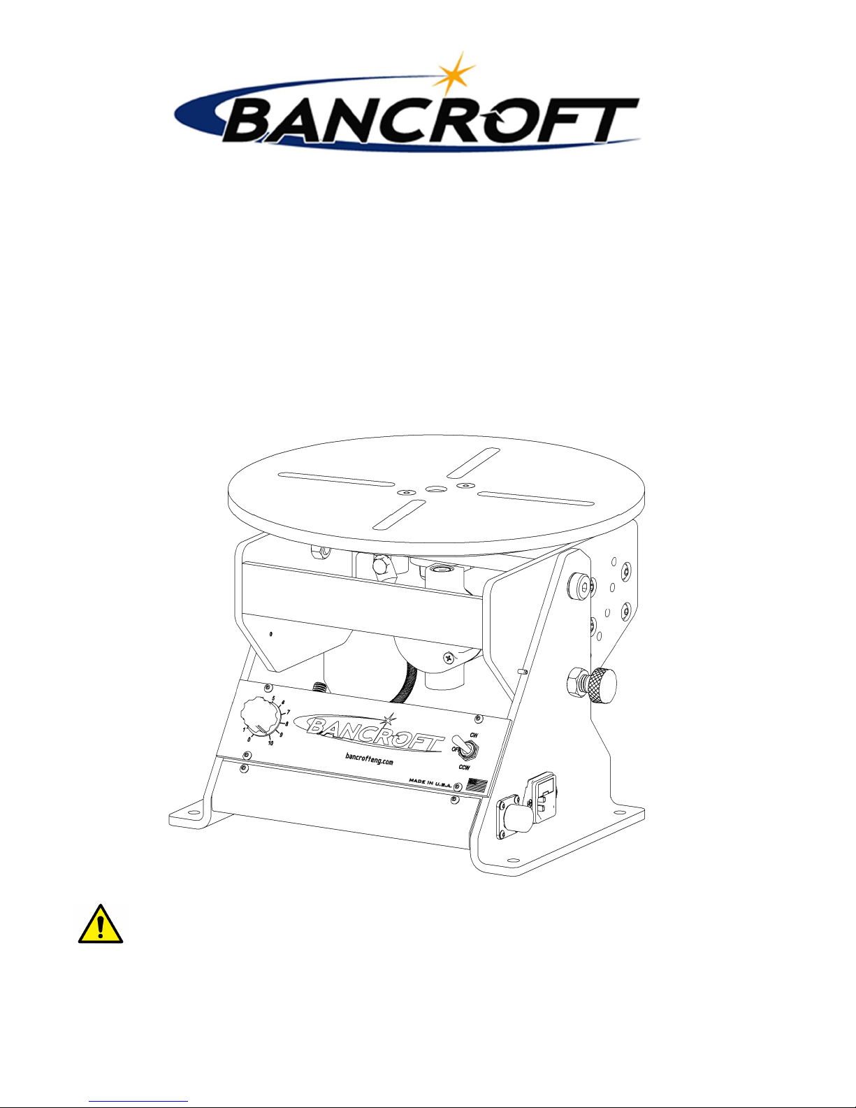
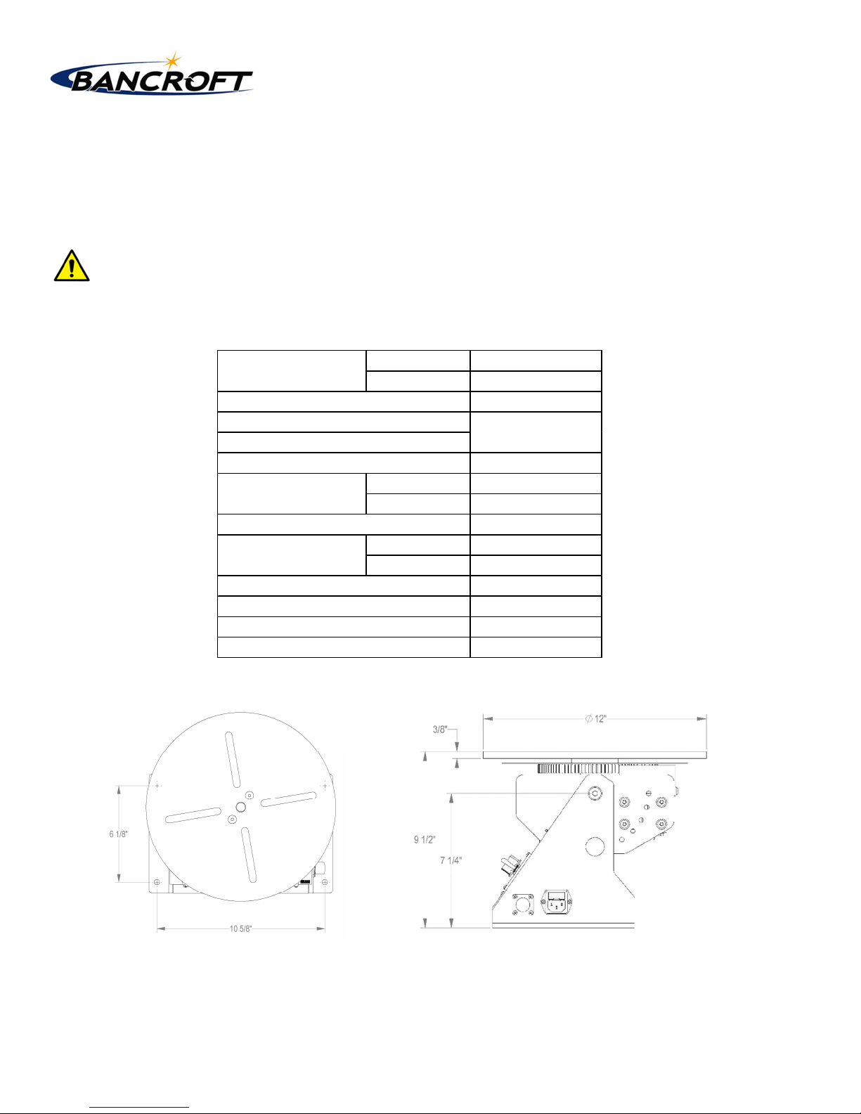
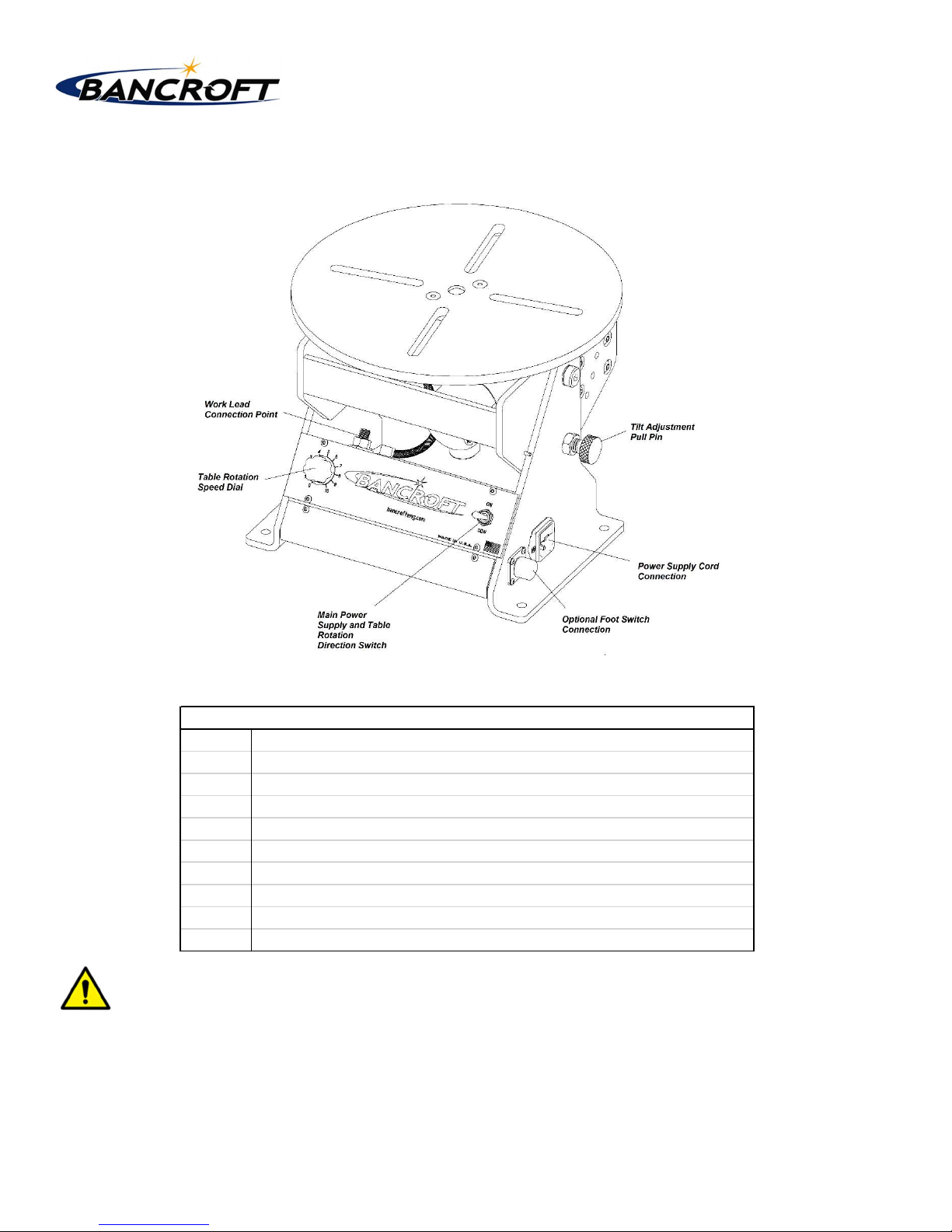
TT-100 Welding Positioner
Bancroft Engineering, LLC
21550 Doral Road Waukes a, WI 53186
P one: (262)786-1880
www.bancrofteng.com
V1.0
Page
SAFETY INFORMATION
ELECTRICAL SHOCK CAN CAUSE INJURY OR DEATH
Electrical equipment must be installed and maintained in accordance wit t e National Electrical Code, NFPA 70, and all local codes. Maintain Mig-
Guns, Electrode Holders, Tig Torc es, Plasma Torc es, Work Clamp, Welding Cable, and Welding Mac ines in good, safe operating condition.
Replace worn or damaged insulation. Do not try to repair or service equipment w ile t e power is still on. Do not service or repair equipment
unless you are trained and qualified to do so. T e Electrode and Work (or Ground) circuits are electrically “HOT” w en equipment power is on. At
no time s ould you touc t e Electrode and Electrical Ground at t e same time wit bare skin or wet clot ing w ile t e power is on. Insulate
yourself from work and ground using dry insulation. Keep gas cylinders, c ains, wire ropes, oists, cranes, and elevators away from any part of t e
electrical pat . Always be sure t e work cable makes a good electrical connection wit t e metal being welded. Occasionally c eck all ground
connections to determine if t ey are mec anically strong and electrically adequate for t e current required. T e ground connection s ould be as
close as possible to t e area being welded. W en not welding for any substantial period, make certain t at no part of t e electrode circuit will
accidentally make contact wit t e work or ground.
SMOKE, FUMES, AND GASES CAN BE DANGEROUS TO YOUR HEALTH
Keep smoke, fumes, and gases from your breat ing zone and t e general area. Smoke, fumes, and gases from t e welding or cutting process are of
various types and strengt s. To ensure your safety, do not breat e t ese fumes or gases. Ventilation must be adequate to remove smoke, fumes,
and gases during t e welding procedure to protect operators and ot ers in t e immediate area. Never Ventil te with Oxygen, because oxygen
supports and vigorously accelerates fire.
HOT PARTS
Hot parts can cause serious burns. T e area at and near t e work being welded s ould be andled wit proper gloves. Proper clot ing s ould be
worn to prevent spatter or c ipped slag from causing burns. Never pick up welded material until it as properly cooled.
MOVING PARTS MAY CAUSE INJURY
Have only qualified people remove guards or covers for performing maintenance and troubles ooting. Moving parts suc as gears can maim
fingers or ands and catc loose clot ing. Keep tools, ands, air and clot ing away from moving parts. Be sure to reinstall all panels and guards
before operating equipment.
FALLING EQUIPMENT
Lift only t e unit to be moved wit out any running gear or accessories t at may be attac ed to it. Use equipment of a proper size to lift
and move t e unit. Falling equipment can cause personal injury and equipment damage.
IMPORTANT - Protect yourself and ot ers! Remember t at safety depends on you. T e operator, supervisor, and elper must
read and understand all warning and safety information provided in t ese instructions. Severe injury or de th could result if
equipment is not properly installed, used and maintained. Training and proper supervision are most important for a safe
work place. Installation, operation, repair work, and maintenance must be performed by qualified personnel. Retain t ese
instructions for future use.