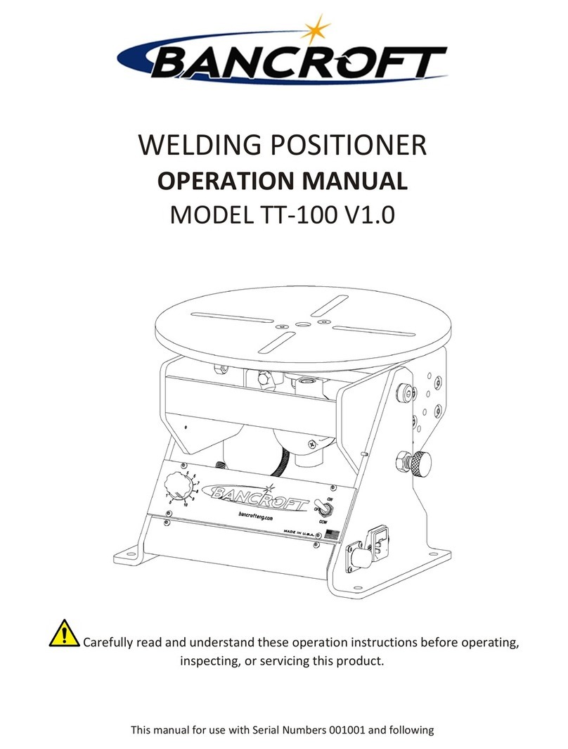
Bancroft TT-500 User manual

WELDING POSITIONER
OPERATION MANUAL
MODEL TT-500 V1.0
Carefully read and unders and hese opera ion ins ruc ions before opera ing,
inspec ing, or servicing his produc .
This manual for use wi h Serial Numbers 201001 and following

TT-500 Welding Posi ioner
Bancroft Engineering, LLC
21550 Doral Road Waukesha, WI 53186
Phone: (262)786-1880
www.bancrof eng.com
V1.0
Page
2
TABLE OF CONTENTS
1. SAFETY INFORMATION……………………………………………………3
2. PACKING LIST………………………………………………………………….4
3. INSPECTION CHECKLIST…………………………………………………..4
4. MACHINE OVERVIEW………………………………………………………5
5. INSTALLATION…………………………………………………………………6
6. OPERATIONS…………………………………..……………….………………7
7. HANDLING MOUNTED OBJECTS……………………………………….8
8. TROUBLESHOOTING…………………………………………………………8
9. DAILY MAINTENANCE……………………………………………………….8
10. WARRANTY…….………………………………………………………………..9
11. ELECTRICAL SCHEMATICS…………………………………………………10
12. PARTS LIST….……………………………………………………………………12

TT-500 Welding Posi ioner
Bancroft Engineering, LLC
21550 Doral Road Waukesha, WI 53186
Phone: (262)786-1880
www.bancrof eng.com
V1.0
Page
3
SAFETY INFORMATION
ELECTRICAL SHOCK CAN CAUSE INJURY OR DEATH
Elec rical equipmen mus be ins alled and main ained in accordance wi h he Na ional Elec rical Code, NFPA 70, and all local codes. Main ain Mig-
Guns, Elec rode Holders, Tig Torches, Plasma Torches, Work Clamp, Welding Cable, and Welding Machines in good, safe opera ing condi ion.
Replace worn or damaged insula ion. Do no ry o repair or service equipmen while he power is s ill on. Do no service or repair equipmen
unless you are rained and qualified o do so. The Elec rode and Work (or Ground) circui s are elec rically “HOT” when equipmen power is on. A
no ime should you ouch he Elec rode and Elec rical Ground a he same ime wi h bare skin or we clo hing while he power is on. Insula e
yourself from work and ground using dry insula ion. Keep gas cylinders, chains, wire ropes, hois s, cranes, and eleva ors away from any par of he
elec rical pa h. Always be sure he work cable makes a good elec rical connec ion wi h he me al being welded. Occasionally check all ground
connec ions o de ermine if hey are mechanically s rong and elec rically adequa e for he curren required. The ground connec ion should be as
close as possible o he area being welded. When no welding for any subs an ial period, make cer ain ha no par of he elec rode circui will
acciden ally make con ac wi h he work or ground.
SMOKE, FUMES, AND GASES CAN BE DANGEROUS TO YOUR HEALTH
Keep smoke, fumes, and gases from your brea hing zone and he general area. Smoke, fumes, and gases from he welding or cu ing process are of
various ypes and s reng hs. To ensure your safe y, do no brea he hese fumes or gases. Ven ila ion mus be adequa e o remove smoke, fumes,
and gases during he welding procedure o pro ec opera ors and o hers in he immedia e area. Never Ventil te with Oxygen, because oxygen
suppor s and vigorously accelera es fire.
HOT PARTS
Ho par s can cause serious burns. The area a and near he work being welded should be handled wi h proper gloves. Proper clo hing should be
worn o preven spa er or chipped slag from causing burns. Never pick up welded ma erial un il i has properly cooled.
MOVING PARTS MAY CAUSE INJURY
Have only qualified people remove guards or covers for performing main enance and roubleshoo ing. Moving par s such as gears can maim
fingers or hands and ca ch loose clo hing. Keep ools, hands, hair and clo hing away from moving par s. Be sure o reins all all panels and guards
before opera ing equipmen .
FALLING EQUIPMENT
Lif only he uni o be moved wi hou any running gear or accessories ha may be a ached o i . Use equipmen of a proper size o lif
and move he uni . Falling equipmen can cause personal injury and equipmen damage.
IMPORTANT - Pro ec yourself and o hers! Remember ha safe y depends on you. The opera or, supervisor, and helper mus
read and unders and all warning and safe y informa ion provided in hese ins ruc ions. Severe injury or de th could resul if
equipmen is no properly ins alled, used and main ained. Training and proper supervision are mos impor an for a safe
work place. Ins alla ion, opera ion, repair work, and main enance mus be performed by qualified personnel. Re ain hese
ins ruc ions for fu ure use.

TT-500 Welding Posi ioner
Bancroft Engineering, LLC
21550 Doral Road Waukesha, WI 53186
Phone: (262)786-1880
www.bancrof eng.com
V1.0
Page
4
PACKING LIST
Confirm he supplied i ems
Before using his produc , confirm all i ems ordered are included in he packaging. In he even an i em is
missing, please con ac Bancrof Engineering or he dealer where you purchased he produc .
PRE-SHIP INSPECTION LIST
Checklis of pre-ship es s and inspec ions
Inspection OK Deficient
Comments
Low Speed Confirma ion
High Speed Confirma ion
CW-OFF-CCW Swi ch Confirma ion
1 Hour es run comple ed
Spindle nu orque confirmed af er run
-
in
(13.2 f -lbs)
Op ional Foo pedal es comple ed
Inspec or Ini ials
ITEM NAME QUANTITY REMARKS
Posi ioner Main Uni 1
Power Cable 1
Opera ing Ins ruc ions 1 This Manual
T-nu s & S uds 4 Op ional
Chuck 1 Op ional
Foo Swi ch 1 Op ional
Digi al Display 1 Op ional

TT-500 Welding Posi ioner
Bancroft Engineering, LLC
21550 Doral Road Waukesha, WI 53186
Phone: (262)786-1880
www.bancrof eng.com
V1.0
Page
5
MACHINE OVERVIEW
The posi ioner is designed and in ended o help posi ion a workpiece for s eady welding. I ro a es a able using a
mo or and le s you adjus he speed and ro a ional direc ion using a con rol dial and 3 posi ion swi ch. An
op ional foo swi ch can be used o s ar /s op he ro a ion.
The able can be se o he necessary il angle using il adjus men handle.
NEVER ADJUST THE TILT ANGLE WITH WORK RESTING ON THE TABLE! REMOVE ALL MATERIAL
INCUDING ANY WORK PIECE HOLDING BEFORE ADJUSTING TILT ANGLE.
SPECIFICATIONS
Posi ioner Dimensional Drawings
Horizon al
Ver ical
Minimum
Max
Heigh
Eccen rici y
Max Load (lbs)
Power Supply
Ex ernal Dimensions
1000
500
20
110V 60Hz AC
0
Table Heigh in Horizon al Posi ion (in)
21-13/16"
Heigh x Wid h x Dep h (in)
21-13/16 x 27 x 24
Table Diame er (in)
Table Ro a ion (RPM)
15.75
Til Angle (Degrees)
-10 o 110
Cen er of Gravi y
during Max Load (in)
4.0
2.0
~260
Weigh of main uni (lbs)
Til Axis Heigh (in)
17.25
Allowable welding curren (A)
500 @ max rpm

TT-500 Welding Posi ioner
Bancroft Engineering, LLC
21550 Doral Road Waukesha, WI 53186
Phone: (262)786-1880
www.bancrof eng.com
V1.0
Page
6
INSTALLATION
1. Confirm he packaged componen s (See Packing Lis , page 4)
2. Ins alla ion Loca ion
a. Well-ven ila ed loca ion. Fumes and gases mus be ven ila ed during welding.
b. Fla surface ha is s rong enough o suppor he weigh s of he moun ed i ems and he
posi ioner. If he surface or floor is weak, unbalanced loads may cause he posi ioner o fall over.
c. DO NOT PLACE THE POSITIONER IN THE FOLLOWING LOCATIONS
i. ANY LOCATION SUBJECT TO WATER
ii. LOCATIONS SUBJECT TO HIGH TEMPERATURES
iii. LOCATIONS NEAR DANGEROUS INFLAMMABLE OBJECTS
iv. LOCATIONS WHERE WELDING SPARKS AND SPATTERS MAY CAUSE FIRE
3. Equipmen Ins alla ion
a. Ins alling he main uni
i. Place he main uni on a fla ins alla ion loca ion.
ii. Secure he uni by inser ing 5/16” or 10mm anchor bol s in he four holes around he
base of he uni .
b. Connec ing he foo swi ch (Op ional)
i. Remove pro ec ive cap.
ii. Connec he cable of he foo swi ch o he ma ing plug on he main uni . Secure he
connec ion wi h he locking nu .
4. Ear h ground conduc or and work lead
a. Properly connec he ear h ground
conduc or on he posi ioner main
uni (labeled wi h a s icker)
b. Direc ly a ach he welding ground
cable/work lead for he power
supply o he ground s ud on
posi ioner, and secure i wi h a nu .
WARNING: Be sure o connec he ear h ground
conduc or o preven an elec ric shock.
5. Connec ing he Power Supply
a. Use specified power supply only.
i. Rou e he power supply cable so i will no be s epped on and in a loca ion were no hing
will be placed on op of he cable.
ii. Connec he power supply cable only af er confirming he safe y of he surrounding area.
iii. Ground he power supply cable properly, and fully plug in o he recep acle.
iv. Do no connec he ear h conduc or o a condui , wa er pipe, or gas pipe.
v. Supply power only af er confirming he oggle swi ch is in he “off” posi ion.

TT-500 Welding Posi ioner
Bancroft Engineering, LLC
21550 Doral Road Waukesha, WI 53186
Phone: (262)786-1880
www.bancrof eng.com
V1.0
Page
7
OPERATIONS
1. Con rol Func ions
2. Opera ional Procedure
This posi ioner is made o con rol TIG welding noise, bu o ensure safe y, use separa e power supplies
for he main uni and he welding power. During opera ion, do no allow he main uni cable and orch
cable o cross each o her.
1 Turn on buildings main power supply and he power o he posi ioner.
2 Adjus he able angle o desired loca ion.
3 A ach a workpiece o he able.
4 Se he ro a ional speed o 2.
5 Selec he direc ion of ro a ion using he 3 posi ion swi ch.
6 If op ional foo pedal is connec ed, press pedal o s ar ro a ion.
7 Adjus he ro a ion speed as needed.
8 Perform welding work.
9 Turn off he uni .
10 Remove he workpiece.
Main Uni

TT-500 Welding Posi ioner
Bancroft Engineering, LLC
21550 Doral Road Waukesha, WI 53186
Phone: (262)786-1880
www.bancrof eng.com
V1.0
Page
8
HANDLING MOUNTED OBJECTS
1. When a aching work, always wear proper personal pro ec ive equipmen including a helme , pro ec ive
glasses, and safe y shoes.
2. A ach and align workpieces properly
3. Check he surrounding area for impedimen s before s ar ing able ro a ion.
4. When placing a workpiece on he able be careful no o crea e a large impac .
5. Do no place a load exceeding he max allowable load, his includes all work holding ooling.
TROUBLESHOOTING
PROBLEM
POSSIBLE CAUSE
SOLUTION
Table does no ro a e.
1
Power cord is no properly secured
Secure properly
2
Blown Fuse
Replace fuse
3
Power cord damaged
Replace he power cord
4
Swi ch
or foo swi ch malfunc ion
Replace he componen
5
Faul y con rol board
Replace he con rol board
6
Faul y mo or
Replace he mo or
7
Bearing damage
Replace he bearing assembly
Fuse Blown
1
Faul y con rol board
Replace he con rol board
2
Faul y
mo or
Replace he mo or
3
Bad power supply
Replace fuse and ry differen power supply
4
Power cord damaged
Replace he power cord
Table does no ro a e
smoo hly.
1
Bearing nu is loose
Torque bearing nu o 13.2 f
-
lbs
2
Bearing damage
Replace he
bearing assembly
3
Spa er from welding adhered o
he gears Clean and apply grease o he gears
Table will no il 1
Seized Adjus men Handle
Lubrica ed and move in bo h direc ions o free
up.
DAILY MAINTENANCE
Inspec able ground for proper ension agains able.
Tes opera ion of 3 posi ion power swi ch
Tes opera ion of op ional foo pedal if provided
Check for any broken wires or loose connec ions
Check for any damaged or worn par s

TT-500 Welding Posi ioner
Bancroft Engineering, LLC
21550 Doral Road Waukesha, WI 53186
Phone: (262)786-1880
www.bancrof eng.com
V1.0
Page
9
WARRANTY
LIMITED WARRANTY: Subjec o he erms and condi ions hereof, B ncroft Engineering, Waukesha, WI warran s i s produc s
o be free from defec s in workmanship and ma erial a he ime of delivery. B ncroft Engineering will honor warran y claims
on produc s as a resul of failure from a defec for a ime period of 90 days from he da e of sale o he original user. Upon
re urn of he merchandise a he user’s expense, B ncroft Engineering reserves he righ o ei her repair or replace as
necessary. This is he only warran y ei her expressed or implied covering his produc .

TT-500 Welding Posi ioner
Bancroft Engineering, LLC
21550 Doral Road Waukesha, WI 53186
Phone: (262)786-1880
www.bancrof eng.com
V1.0
Page
10
ELECTRICAL SCHEMATICS (1)
M in Control Bo rd Wiring Di gr m.
Service or repair of his uni mus be done by qualified personnel only.
Before performing any main enance on his con rol board disconnec he uni from any power supply.

TT-500 Welding Posi ioner
Bancroft Engineering, LLC
21550 Doral Road Waukesha, WI 53186
Phone: (262)786-1880
www.bancrof eng.com
V1.0
Page
11
ELECTRICAL SCHEMATICS (2)
Option l Foot Switch Wiring Di gr m.
Service or repair of his uni mus be done by qualified personnel only.
Before performing any main enance on his con rol board disconnec he uni from any power supply.

TT-500 Welding Posi ioner
Bancroft Engineering, LLC
21550 Doral Road Waukesha, WI 53186
Phone: (262)786-1880
www.bancrof eng.com
V1.0
Page
12
PARTS LIST

TT-500 Welding Posi ioner
Bancroft Engineering, LLC
21550 Doral Road Waukesha, WI 53186
Phone: (262)786-1880
www.bancrof eng.com
V1.0
Page
13
This manual suits for next models
1
Table of contents
Other Bancroft Valve Positioner manuals