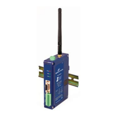
B&B Electronics ZP8 Series User manual

Manual Documentation Number: ZP8D-24RM-0912m 1
B&B Electronics Mfg Co Inc –707 Dayton Rd - PO Box 1040 - Ottawa IL 61350 - www.bb-elec.com
B&B Electronics –Westlink Commercial Park –Oranmore, Galway, Ireland –www.bb-europe.com
Zlinx 868 Radio Modem
ZP8 Series
Documentation Number: ZP8D-24RM-LR-0912m
This product designed and manufactured in Ottawa, Illinois USA
of domestic and imported parts by
707 Dayton Road -- P.O. Box 1040 -- Ottawa, IL 61350 USA
Website: www.bb-elec.com
European Headquarters
B&B Electronics
Westlink Commercial Park -- Oranmore, Co. Galway, Ireland
Website: www.bb-europe.com
B&B Electronics Mfg. Co. Inc. –2009

2 Manual Documentation Number: ZP8D-24RM-LR -0912m
B&B Electronics Mfg Co Inc –707 Dayton Rd - PO Box 1040 - Ottawa IL 61350 - Ph 815-433-5100 - Fax 815-433-5104 –www.bb-elec.com
B&B Electronics –Westlink Commercial Park –Oranmore, Galway, Ireland –Ph +353 91-792444 –Fax +353 91-792445 –www.bb-europe.com
Table of Contents
Introduction 4
RADIO FREQUENCY BASICS 4
What is dBm? 4
Lower Frequencies = Better Propagation 4
Range performance is not just function of transmit power 5
You Must Consider RF Noise 5
Fade margin is critical for reliable operation in rain, snow, or the
presence of interference 6
Remember Your Math 7
RF Attenuation and Line of Sight 7
Latency and Packetization 10
RADIO MODEM INTRODUCTION 10
Package Contents 11
HARDWARE INSTALLATION 12
Dip Switch Settings 12
Mounting and Power 12
Serial Connections 13
RS-232 13
RS-422/485 14
Wireless RF Link Output 16
RADIO FREQUENCY INFORMATION 17
Zlinx Manager Software 18
INSTALLATION 18
SET UP19
OFF-LINE CONFIGURATION SCREEN 21
ON-LINE CONFIGURATION 24
TEST /TROUBLESHOOT 28
FIRMWARE UPDATE 30
Specifications 32
Things to think about 34
HISTORY 34
RF POWER OUTPUT AND ANTENNA CONSIDERATIONS 34
868 RADIO SERIAL DATA TRANSMISSION DUTY CYCLE 34
OVER-THE-AIR DATA RATE 35
DUTY CYCLE 35
RECEIVE SENSITIVITY 36

Manual Documentation Number: ZP8D-24RM-0912m 3
B&B Electronics Mfg Co Inc –707 Dayton Rd - PO Box 1040 - Ottawa IL 61350 - www.bb-elec.com
B&B Electronics –Westlink Commercial Park –Oranmore, Galway, Ireland –www.bb-europe.com
RS232 SERIAL DATA SPECIFICATION 36
REPEATERS AND MESH NETWORKS 37
Command Mode 37
AT COMMAND MODE 37
To Enter AT Command Mode: 37
To send AT Commands 38
To Exit AT Command Mode: 38
COMMAND REFERENCE TABLES 39
Special Commands 39
Addressing 39
Serial Interfacing (I/O) 41
I/O Commands 42
Diagnostic Commands 44
AT Command Options 44
Node Identification 45
Security Commands 46
API OPERATION 47
API Frame Specifications 47
API Operation (AP Parameter = 1) 47
API Operation –with Escape Characters (AP Parameter = 2) 48
API Frames 49
Modem Status 50
AT Command 51
AT Command –Queue Parameter Value 52
AT Command Response 53
Remote AT Command Request 54
Remote Command Response 55
Transmit Request 56
Explicit Addressing Command Frame 57
Transmit Status 58
Receive Packet 58
Explicit RX Indicator 59

4 Manual Documentation Number: ZP8D-24RM-LR -0912m
B&B Electronics Mfg Co Inc –707 Dayton Rd - PO Box 1040 - Ottawa IL 61350 - Ph 815-433-5100 - Fax 815-433-5104 –www.bb-elec.com
B&B Electronics –Westlink Commercial Park –Oranmore, Galway, Ireland –Ph +353 91-792444 –Fax +353 91-792445 –www.bb-europe.com
Introduction
Radio Frequency Basics
What is dBm?
Radio Frequency (RF) power is measured in milli-Watts (mW) or, more
usefully, in a logarithmic scale of decibels (dB), or decibels referenced to 1
mW of power (dBm). Since RF power attenuates as a logarithmic function,
the dBm scale is most useful. Here are some examples of how these scales
relate:
1mW = 0dBm
A 2-fold increase in power yields 3dBm of signal.
2mW = 3dBm
A 10-fold increase in power yields 10dBm of signal.
4mW = 6dBm
A 100-fold increase in power yields 20dBm of
signal.
10mW = 10dBm
100mW = 20dBm
1W = 30dBm
Lower Frequencies = Better Propagation
Industrial applications typically operate in “license free” frequency bands, also
referred to as ISM (Industrial, Scientific and Medical). The frequencies and
power of these bands varies from country to country. The most common
frequencies encountered are:
2.4 GHz –nearly worldwide
915 MHz band –North America, South America, some other countries
868 MHz band –Europe
As frequency rises, available bandwidth typically rises, but distance and ability
to overcome obstacles is reduced. For any given distance, a 2.4 GHz
installation will have roughly 8.5 dB of additional path loss when compared to
900 MHz. However, lower frequencies require larger antennas to achieve the
same gain.

Manual Documentation Number: ZP8D-24RM-0912m 5
B&B Electronics Mfg Co Inc –707 Dayton Rd - PO Box 1040 - Ottawa IL 61350 - www.bb-elec.com
B&B Electronics –Westlink Commercial Park –Oranmore, Galway, Ireland –www.bb-europe.com
Range performance is not just function of transmit power
The more sensitive the radio, the lower the power signal it can successfully
receive, stretching right down to the noise floor. There is so much variety in
“specsmanship” for radio sensitivity, that it is difficult to make a meaningful
comparison between products. The most meaningful specification is
expressed at a particular bit error rate and will be given for an ideal
environment shielded from external noise. Unless you’re in a high RF noise
environment (typically resulting from numerous similar-frequency radio
transmitters located nearby), the odds are good that the noise floor will be
well below the receive sensitivity, so the manufacturer’s rated receive
sensitivity will be a key factor in your wireless system and range estimates.
You can often improve your receive sensitivity, and therefore your range, by
reducing data rates over the air. Receive sensitivity is a function of the
transmission baud rate so, as baud rate goes down, the receive sensitivity
goes up. Many radios give the user the ability to reduce the baud rate to
maximize range.
The receive sensitivity of a radio also improves at lower frequencies,
providing another significant range advantage of 900 MHz (vs. 2.4 GHz) - as
much as six to twelve dB!
You Must Consider RF Noise
RF background noise comes from many sources, ranging from solar activity
to high frequency digital products to all forms of other radio communications.
That background noise establishes a noise floor which is the point where the
desired signals are lost in the background ruckus. The noise floor will vary
by frequency.
Typically the noise floor will be lower than the receive sensitivity of your
radio, so it will not be a factor in your system design. If, however, you’re in
an environment where high degrees of RF noise may exist in your frequency
band, then use the noise floor figures instead of radio receive sensitivity in
your calculations. If you suspect this is the case, a simple site survey to
determine the noise floor value can be a high payoff investment.
When in doubt, look about. Antennas are everywhere nowadays - on the
sides of buildings, water towers, billboards, chimneys, even disguised as
trees. Many sources of interference may not be obvious.

6 Manual Documentation Number: ZP8D-24RM-LR -0912m
B&B Electronics Mfg Co Inc –707 Dayton Rd - PO Box 1040 - Ottawa IL 61350 - Ph 815-433-5100 - Fax 815-433-5104 –www.bb-elec.com
B&B Electronics –Westlink Commercial Park –Oranmore, Galway, Ireland –Ph +353 91-792444 –Fax +353 91-792445 –www.bb-europe.com
Fade margin is critical for reliable operation in rain, snow, or
the presence of interference
Fade margin is a term critical to wireless success. Fade margin describes
how many dB a received signal may be reduced by without causing system
performance to fall below an acceptable value. Walking away from a newly
commissioned wireless installation without understanding how much fade
margin exists is the number one cause of wireless woes.
Establishing a fade margin of no less than 10dB in good weather conditions
will provide a high degree of assurance that the system will continue to
operate effectively in a variety of weather, solar, and RF interference
conditions.
There are a number of creative ways to estimate fade margin of a system
without investing in specialty gear. Pick one or more of the following and use
it to ensure you’ve got a robust installation:
a. Some radios have programmable output power. Reduce the power until
performance degrades, then dial the power back up a minimum of
10dB. Remember again, doubling output power yields 3 dB, and an
increase of 10dB requires a ten-fold increase in transmit power.
b. Invest in a small 10dB attenuator (pick the correct one for your radio
frequency!). If you lose communications when you install the attenuator
installed in-line with one of your antennas, you don’t have enough fade
margin.
c. Antenna cable is lossy, more so at higher frequencies. Specifications
vary by type and manufacturer so check them yourself but, at 900MHz,
a coil of RG58 in the range of 50 to 100 feet (15 to 30 m) will be 10dB.
At 2.4GHz, a cable length of 20-40 feet (6 to 12 m) will yield 10dB. If
your system still operates reliably with the test length of cable installed,
you’ve got at least 10dB of fade margin.

Manual Documentation Number: ZP8D-24RM-0912m 7
B&B Electronics Mfg Co Inc –707 Dayton Rd - PO Box 1040 - Ottawa IL 61350 - www.bb-elec.com
B&B Electronics –Westlink Commercial Park –Oranmore, Galway, Ireland –www.bb-europe.com
Remember Your Math
Contrary to popular opinion, no black art is required to make a reasonable
prediction of the range of a given radio signal. Several simple concepts must
be understood first, and then we can apply some simple rules of thumb.
The equation for successful radio reception is:
TX power + TX antenna gain –Path loss –Cabling loss + RX antenna
gain –10dB fade margin
> RX Radio sensitivity or (less commonly) RF noise floor
Note that most of the equation’s parameters are easily gleaned from the
manufacturer’s data. That leaves only path loss and, in cases of heavy RF
interference, RF noise floor as the two parameters that you must
established for your particular installation.
In a perfect world, you will measure your path loss and your RF noise
conditions. For the majority of us that don’t, there are rules of thumb to
follow to help ensure a reliable radio connection.
RF Attenuation and Line of Sight
In a clear path through the air, radio signals attenuate with the square of
distance. Doubling range requires a four-fold increase in power, therefore:
• Halving the distance decreases path loss by 6dB.
• Doubling the distance increases path loss by 6dB.
When indoors, paths tend to be more complex, so use a more aggressive
rule of thumb, as follows:
• Halving the distance decreases path loss by 9dB.
• Doubling the distance increases path loss by 9dB.
Radio manufacturers advertise “line of sight” range figures. Line of sight
means that, from antenna A, you can see antenna B. Being able to see the
building that antenna B is in does not count as line of sight. For every
obstacle in the path, de-rate the “line of sight” figure specified for each
obstacle in the path. The type of obstacle, the location of the obstacle, and
the number of obstacles will all play a role in path loss.
Visualize the connection between antennas, picturing lines radiating in an
elliptical path between the antennas in the shape of a football. Directly in the
center of the two antennas the RF path is wide with many pathways. A
single obstacle here will have minimal impact on path loss. As you approach
each antenna, the meaningful RF field is concentrated on the antenna itself.
Obstructions located close to the antennas cause dramatic path loss.


8 Manual Documentation Number: ZP8D-24RM-LR -0912m
B&B Electronics Mfg Co Inc –707 Dayton Rd - PO Box 1040 - Ottawa IL 61350 - Ph 815-433-5100 - Fax 815-433-5104 –www.bb-elec.com
B&B Electronics –Westlink Commercial Park –Oranmore, Galway, Ireland –Ph +353 91-792444 –Fax +353 91-792445 –www.bb-europe.com
Be sure you know the distance between antennas. This is often
underestimated. If it’s a short-range application, pace it off. If it’s a long-
range application, establish the actual distance with a GPS or Google Maps.
The most effective way to reduce path loss is to elevate the antennas. At
approximately 6 feet high (2 m), line of sight due to the Earth’s curvature is
about 3 miles (5 km), so anything taller than a well-manicured lawn
becomes an obstacle.
Weather conditions also play a large role. Increased moisture in the air
increases path loss. The higher the frequency, the higher the path loss.
Beware leafy greens. While a few saplings mid-path are tolerable, it’s very
difficult for RF to penetrate significant woodlands. If you’re crossing a
wooded area you must elevate your antennas over the treetops.
Industrial installations often include many reflective obstacles leading to
numerous paths between the antennas. The received signal is the vector
sum of each of these paths. Depending on the phase of each signal, they
can be added or subtracted. In multiple path environments, simply moving
the antenna slightly can significantly change the signal strength.
Some obstacles are mobile. More than one wireless application has been
stymied by temporary obstacles such as a stack of containers, a parked
truck or material handling equipment. Remember, metal is not your friend.
An antenna will not transmit out from inside a metal box or through a
storage tank.
Path Loss Rules of Thumb:
To ensure basic fade margin in a perfect line of sight
application, never exceed 50% of the manufacturer’s
rated line of sight distance. This in itself yields a
theoretical 6dB fade margin –still short of the required
10dB.
De-rate more aggressively if you have obstacles between
the two antennas, but not near the antennas.
De-rate to 10% of the manufacture’s line of sight
ratings if you have multiple obstacles, obstacles
located near the antennas, or the antennas are
located indoors.

Manual Documentation Number: ZP8D-24RM-0912m 9
B&B Electronics Mfg Co Inc –707 Dayton Rd - PO Box 1040 - Ottawa IL 61350 - www.bb-elec.com
B&B Electronics –Westlink Commercial Park –Oranmore, Galway, Ireland –www.bb-europe.com
Antennas
Antennas increase the effective power by focusing the radiated
energy in the desired direction. Using the correct antenna not only
focuses power into the desired area but it also reduces the amount
of power broadcast into areas where it is not needed.
Wireless applications have exploded in popularity with everyone
seeking out the highest convenient point to mount their antenna.
It’s not uncommon to arrive at a job site to find other antennas
sprouting from your installation point. Assuming these systems are
spread spectrum and potentially in other ISM or licensed frequency
bands, you still want to maximize the distance from the antennas
as much as possible. Most antennas broadcast in a horizontal
pattern, so vertical separation is more meaningful than horizontal
separation. Try to separate antennas with like-polarization by a
minimum of two wavelengths, which is about 26 inches (0.66 m) at
900 MHz, or 10 inches (0.25 m) at 2.4 GHz.
Cable Loss
Those high frequencies you are piping to your antennas don’t
propagate particularly well through cable and connectors. Use high
quality RF cable between the antenna connector and your antenna
and ensure that all connectors are high quality and carefully
installed. Factor in a 0.2 dB loss per coaxial connector in addition
to the cable attenuation itself. Typical attenuation figures for two
popular cable types are listed below.
Loss per 10 feet (3 meters) of cable
length
Frequency
RG-58U
LMR-400
900 MHz
1.6 dB
0.4 dB
2.4 GHz
2.8 dB
0.7 dB
While long cable runs to an antenna create signal loss, the benefit
of elevating the antenna another 25 feet (7.6 m) can more than
compensate for those lost dB.

10 Manual Documentation Number: ZP8D-24RM-LR -0912m
B&B Electronics Mfg Co Inc –707 Dayton Rd - PO Box 1040 - Ottawa IL 61350 - Ph 815-433-5100 - Fax 815-433-5104 –www.bb-elec.com
B&B Electronics –Westlink Commercial Park –Oranmore, Galway, Ireland –Ph +353 91-792444 –Fax +353 91-792445 –www.bb-europe.com
Latency and Packetization
Before you lift a finger towards the perfect wireless installation, think about
the impact of wireless communications on your application. Acceptable bit
error rates are many orders of magnitude higher than wired
communications. Most radios quietly handle error detection and retries for
you - at the expense of throughput and variable latencies.
Software must be well designed and communication protocols must be
tolerant of variable latencies. Not every protocol can tolerate simply
replacing wires with radios. Protocols sensitive to inter-byte delays may
require special attention or specific protocol support from the radio. Do your
homework up front to confirm that your software won’t choke, that the
intended radio is friendly towards your protocol, and that your
application software can handle it as well.
Radio Modem Introduction
Easy to install, up to 40km range No wires, no cables!
Zlinx radio modems get your
data moving farther, easier, and at less cost than running
cable. Plug-n-play, Modbus compatible, signal strength
indicator, space saving DIN rail mounting. Heavy-duty,
wide temperature design handles most industrial power
configurations and tough indoor/outdoor environments.
NOTE: All range references made in this manual are best
case scenarios.
Model #
Frequency
Single Channel
Radio
Power
Receive
Sensitivity
RF Data Rate
ZP8D-240RM-LR
869.525 MHz
4 Levels:
1mW
23mW
100mW
158mW
316mW
-112dB
@24kbps
24kbps
Throughput
10% Duty Cycle

Manual Documentation Number: ZP8D-24RM-0912m 11
B&B Electronics Mfg Co Inc –707 Dayton Rd - PO Box 1040 - Ottawa IL 61350 - www.bb-elec.com
B&B Electronics –Westlink Commercial Park –Oranmore, Galway, Ireland –www.bb-europe.com
The radio modem has 4 operating modes:
1. Idle Mode
Checks for Valid RF Data received and discards invalid
data.
Checks for serial data to be packaged and RF transmitted
Received Valid RF data in buffer to be output serially
Checks for Command Mode commands
2. Transmit Mode
Exits Idle mode
Packages serial data (256 bytes max)
Checks operating duty cycle for past hour, if ≤10%
including data to be currently sent, transmits it.
If duty cycle check exceeds 10%, radio buffers data until it
can be sent, the CTS line is set low.
When duty cycle returns to normal, the CTS line is set
high and the radio sends buffered data to destination
radio.
Returns to Idle
3. Receive Mode –Valid data is sent to serial port.
Returns to Idle Mode.
4, Command Mode
Enters AT Command mode with +++ sent to serial input
with Guard Time before and after. Exits after Timeout
Is set to enter API 1 or API 2 operation.
Package Contents
Radio Modem
Antenna
Software CD
Quick Start Guide and Manual on CD
10 Commandants white paper
Requires 18-30VAC or 10-48VDC Power Supply (not included)
XP8D-240RM-LR = 6.0W max

12 Manual Documentation Number: ZP8D-24RM-LR -0912m
B&B Electronics Mfg Co Inc –707 Dayton Rd - PO Box 1040 - Ottawa IL 61350 - Ph 815-433-5100 - Fax 815-433-5104 –www.bb-elec.com
B&B Electronics –Westlink Commercial Park –Oranmore, Galway, Ireland –Ph +353 91-792444 –Fax +353 91-792445 –www.bb-europe.com
Hardware Installation
RECOMMENDED PRACTICE BEFORE INSTALLATION
Please set up, bench test and familiarize yourself with a pair or
set of these radios using RS-232 connections before taking
them out into the field for installation. If using RS422 or RS-485
connections, verify your settings and operation using RS-232
connections and the RSSI Range Test before connecting as 4-
wire RS422/485 or as 2-wire RS485. Do not connect your
devices to the terminal blocks or change the switch 4 from ON
position until setup is complete, it may interfere with the
configuration software settings.
Dip Switch Settings
Dipswitch
OFF
ON
1
4-wire
2-wire
2
4-wire
2-wire
3
No termination
Termination
4
4W RS-422/485
2W RS-485
Mounting and Power
Install on properly grounded DIN rail
oOperating Temperature is -40C to 85C
oOperating Humidity is 10-90% non-condensing
Connect Power Supply
oPower supply is 10-48 VDC or 18-30 VAC
10-48 VDC Auto Polarity or 18-30 VAC

Manual Documentation Number: ZP8D-24RM-0912m 13
B&B Electronics Mfg Co Inc –707 Dayton Rd - PO Box 1040 - Ottawa IL 61350 - www.bb-elec.com
B&B Electronics –Westlink Commercial Park –Oranmore, Galway, Ireland –www.bb-europe.com
Serial Connections
RS-232
RS-232 Always present on DB9
RS-232 (DCE) Pinouts & Signals
DB9F
Pin
Signal Name
Direction
1
Carrier Detect
Out
2
Receive Data
Out
3
Transmit Data
In
4
Data Terminal
Ready
In
5
Signal Ground
---
6
Data Set Ready
Out
7
Request To Send
In
8
Clear To Send
Out
9
Not used
---

14 Manual Documentation Number: ZP8D-24RM-LR -0912m
B&B Electronics Mfg Co Inc –707 Dayton Rd - PO Box 1040 - Ottawa IL 61350 - Ph 815-433-5100 - Fax 815-433-5104 –www.bb-elec.com
B&B Electronics –Westlink Commercial Park –Oranmore, Galway, Ireland –Ph +353 91-792444 –Fax +353 91-792445 –www.bb-europe.com
RS-485 (2Wire)
RS-422/485 (4Wire)
RS-422/485

Manual Documentation Number: ZP8D-24RM-0912m 15
B&B Electronics Mfg Co Inc –707 Dayton Rd - PO Box 1040 - Ottawa IL 61350 - www.bb-elec.com
B&B Electronics –Westlink Commercial Park –Oranmore, Galway, Ireland –www.bb-europe.com

16 Manual Documentation Number: ZP8D-24RM-LR -0912m
B&B Electronics Mfg Co Inc –707 Dayton Rd - PO Box 1040 - Ottawa IL 61350 - Ph 815-433-5100 - Fax 815-433-5104 –www.bb-elec.com
B&B Electronics –Westlink Commercial Park –Oranmore, Galway, Ireland –Ph +353 91-792444 –Fax +353 91-792445 –www.bb-europe.com
Wireless RF Link Output
Zlinx Radio modems offer a source (PNP) transistor output when
the wireless signal strength drops below a critical level (link
failure or missed packets)
40 mA max current

Manual Documentation Number: ZP8D-24RM-0912m 17
B&B Electronics Mfg Co Inc –707 Dayton Rd - PO Box 1040 - Ottawa IL 61350 - www.bb-elec.com
B&B Electronics –Westlink Commercial Park –Oranmore, Galway, Ireland –www.bb-europe.com
Note: In order for the RSSI LED to continuously indicate the signal strength, set the
RP command (RSSI PWM timer) to FF. The RSSI light typically goes out after the
last data is received.
Radio Frequency Information
The ZP8D-24RM-LR has an indoor range of up to 550m
and an outdoor range of up to 40km

18 Manual Documentation Number: ZP8D-24RM-LR -0912m
B&B Electronics Mfg Co Inc –707 Dayton Rd - PO Box 1040 - Ottawa IL 61350 - Ph 815-433-5100 - Fax 815-433-5104 –www.bb-elec.com
B&B Electronics –Westlink Commercial Park –Oranmore, Galway, Ireland –Ph +353 91-792444 –Fax +353 91-792445 –www.bb-europe.com
These ranges are for line of sight installations using the
supplied antenna. Performance may vary depending on your
particular installation.
The antenna connection on the radio modem is an RPSMA
(Reverse Polarity SMA) female plug.
B&B Electronics has a wide variety of accessory antennas.
Visit www.bb-elec.com for more information.
Zlinx Manager Software
Installation
The Zlinx Manager Software is provided on CD.
Insert the CD into the drive.
Model #
Frequency
Single Channel
Radio
Power
Receive
Sensitivity
RF Data Rate
ZP8D-240RM-LR
869.525 MHz
4 Levels:
1mW
23mW
100mW
158mW
316mW
-112db
@24kbps
24kbps
Throughput
10% Duty Cycle

Manual Documentation Number: ZP8D-24RM-0912m 19
B&B Electronics Mfg Co Inc –707 Dayton Rd - PO Box 1040 - Ottawa IL 61350 - www.bb-elec.com
B&B Electronics –Westlink Commercial Park –Oranmore, Galway, Ireland –www.bb-europe.com
The installation program should auto start.
Follow the on screen prompts.
Set Up
1. Connect your PC to the modem using a straight through serial
cable.
2. Start the Zlinx Manager Software and click on the radio modem
button.

20 Manual Documentation Number: ZP8D-24RM-LR -0912m
B&B Electronics Mfg Co Inc –707 Dayton Rd - PO Box 1040 - Ottawa IL 61350 - Ph 815-433-5100 - Fax 815-433-5104 –www.bb-elec.com
B&B Electronics –Westlink Commercial Park –Oranmore, Galway, Ireland –Ph +353 91-792444 –Fax +353 91-792445 –www.bb-europe.com
3. The radio modem launcher screen will appear
4. Click on the Radio Modem Configuration button to configure the
modem on-line or the Radio Modem Configuration Button
(offline) to configure the modem offline. Follow the on screen
directions to configure the modem. Note: using the off-line
configuration button skips the auto modem discovery process.
This manual suits for next models
1
Table of contents
Other B&B Electronics Radio Modem manuals

B&B Electronics
B&B Electronics ZP9D-115RM-LR User manual

B&B Electronics
B&B Electronics Zlinx Xtreme IP67 ZXT9-RM User manual

B&B Electronics
B&B Electronics Zlinx ZP24D-250RM-SR User manual

B&B Electronics
B&B Electronics Zlinx ZP Series User manual

B&B Electronics
B&B Electronics Zlinx Xtreme ZXT9-RM User manual

B&B Electronics
B&B Electronics Zlinx ZP Series User manual

B&B Electronics
B&B Electronics Zlinx ZP24D-250RM-SR User manual

B&B Electronics
B&B Electronics Zlinx ZP Series User manual

B&B Electronics
B&B Electronics Zlinx Xtreme ZXT9-RM User manual

B&B Electronics
B&B Electronics ZP9D-115RM-LR User manual