B&PLUS RCS600 User manual

Issue 2023.04.24
No. T318C05Oe
O
600W type
RCS600 for 12V・24V・48V battery
Standard head Long distance head
Thank you very much for purchasing the Wireless charging system RCS600 of B&PLUS.
Please read the instruction manual before use and please use the products correctly.
Wireless charging system
Manual
● This product, which is one of those high frequency utilization equipment of Radio Law.
In the case of using in Japan, please apply for a permission application for high frequency utilization
equipment permission to Ministry of Internal Aairs and Communications.
In the case of using the product out side Japan, please take appropriate action after confirming by
yourself the standards and regulations to which the customer's system should conform. If you have any
questions about the application, please contact our sales department.
● For the control communication device that is installed in the product, there is no need for (diploma)
radio station authorization of the Minister as it corresponds to“ a weak radio station (weak radio
equipment)”to. However, please be careful when operating it as it may aect electronic devices (sensor
devices) and medical devices (pacemakers, etc.).
● In principle, repairs will be charged in the event of failure or damage caused by re, earthquake, acts by a third
party, other accidents, intentional or negligent use by the customer, misuse, or use under abnormal conditions.
● The Company is not liable for any incidental damages (loss of business profit, etc.) resulting from the use or
inability to use this machine.
● If this unit is used for purposes other than battery charging, we cannot guarantee it.
Request for use
Disclaimer
※ Specications subject to change without notice.
If there is a point of notice about the contents of this document, hope you'll give me your contact us, thank you.

For safety precautions
Please read, please use it correctly and full attention to safety this "Safety Precautions" before use.
Incorrect handling may cause not only malfunction or failure, leading to an accident or injury.
Also in order to prevent damage or injury, please look after.
■ About Warnings
You are viewing mark with the following notes on safety in this manual.
It indicates that if ignoring this display, and operate the product in an
improper manner, serious injury or possible death can occur.
If you ignore the display, and operate the product in an improper manner, it
indicates that there is a possibility that people bear the damage, the potential and
property damage may occur.
■ About designation
The symbol shown in the instruction manual and product, have the following meanings.
Shows the attention "Please be careful".
I shows that please without doing the "forbidden".
I indicates mandatory "Please always run".
Attention
Caution
Do not do the resolution and remodeling
Failure to do so may result in re, electric shock or malfunction. In addition, there is a risk that can
lead to serious injury. When I perform the resolution and remodeling, a guarantee may not be received.
Do not use it as trouble and an abnormal state
Smoke, or in the case of such an abnormal state when abnormal noise or oensive smell is,
please stop using it immediately. The Malfunction or electric shock , the cause of the re.
The equipment inside, do not insert foreign objects and water
It may cause re, smoke, electric shock, or malfunction due to malfunction or short cir-
cuit.
This product is compatible with 12 VDC or 24 VDC or
48 VDC
lead battery and lithium ion bat-
tery.
Because voltage current setting may be required depending on the type of battery
and conditions of use, be sure to contact our sales representative when purchasing.
In accordance with the instructions, please do the wiring and mounting
Please ensure proper procedure to street work. The malfunction or cause of the re.
Caution

Attention
If you want to dispose of this product, you will be disposed of as industrial waste
Please dispose of in accordance with waste disposal regulations specied.
Please be sure to use the specied parts and accessories
The malfunction or accident, the cause of the re.
Please do not take any action in the hot-line state
If you want to support the installation, maintenance, and failure, after conrming that the main circuit breaker
(power board) is always out, please work. When working with hot-state, there is a potential for electric shock.
Please use the power supply as set forth in the specication always
If it is used in power outside of the specications such as a power in excess of the
rated voltage, there is a risk of overheating, re or malfunction.
Keep the specied temperature range
Use the product so that its temperature does not exceed the specied temperature range.
Using outside the specication range may cause equipment failure due to heat generation.
To contact a specialized dealer or installation of equipment (installation), the wiring
Improper by doing installation work on your own, you will malfunction or an electrical
shock, the cause of the re.
Do not put your hands or metal objects between the coils during operation
There and heat generated by induction heating, the potential to catch re.
Do not install in a place that may be exposed to high temperature
When installed in a place such as hot air heater or direct sunlight directly, it could
cause a malfunction or re.
Do not block the cooling fan
Heat build up inside and cause malfunction or re.
Do not touch the high temperature part
Work for a while or immediately after operation, please do not touch the (power sup-
ply unit, charging unit, head part) hot spots. Doing so could result in burns.
Do not use a deteriorated battery
Charging a deteriorated battery may cause the battery to overheat, resulting in an accident or fire.
Replace the battery regularly according to the battery manufacturer’s recommended replacement time.
Do not use head cables other than those specied by us.
If you use a cable other than the specied one, the cable may generate heat, resulting in an
accident, malfunction, or re. Be sure to use the specied cable.
Do not disconnect the battery while charging
If the battery is disconnected during charging, it may cause an accident, malfunction or re.
Be sure to check that the battery is not charged before disconnecting the battery.
Please be careful about the inuence due to the installation environment
Please be careful about the inuence on the material degradation due to the installation environment and the intru-
sion of foreign material.Especially when using it outdoors, please install it with less inuence from ultraviolet rays.

About the description in the manual
Shown in the explanation for12V type
●This manual is for 600W wireless power supply system for 12V or 24V or 48V battery.
The following label is displayed in the explanation of the specic specications.
Please do not confuse the description, and make sure to check the corresponding part.
Shown in the explanation for 24V type
Shown in the explanation for 48V type
RCS600
CA
12
mark is posted as a representative.
RCS600
CA
24
mark is posted as a representative.
RCS600
CA
48
mark is posted as a representative
RCS600B
CA
12
RCS600B
CA
24
RCS600B
CA
48
RCS600
CA
12
RCS600
CA
24
RCS600
CA
48
normal open normal close
normal open normal close
12V type RCS600-CA12 RCS600B-CA12
24V type RCS600-CA24 RCS600B-CA24
48V type RCS600-CA48 RCS600B-CA48
normal open type: external connection pin (Pin) is arranged as shown on the right. When
the dry contact is ON, charging starts, and when it is OFF, charging stops. To start
charging, it is necessary to turn it on on the ON connector, separate wiring, or on the
control side.
normal close type: the external connection pin (Pin) is arranged as shown on the right.
When the dry contact is OFF, charging starts, and when it is ON, charging stops.
Pin1.charge start
Pin14.GND
dry contact
internal circuit internal circuit
normal open
Pin1.charge stop
Pin14.GND
dry contact
normal close
● The charging unit of this product have two specications, normal open type and normal close type.
Please see P.17 for details.
Attention
Do not use under conditions with excessive vibration or impact
Using it beyond the conditions may cause an accident, malfunction or re. Be sure to use it within
the specications.
Do not use in a state where it is lled with dust containing oil and moisture and accumulated.
Accumulation inside the device may cause a malfunction or re. Clean it regularly or put it in a
case to protect it.

■ Index ■
1. Product summary
- System conguration ・・・・・・・・・・・・・・・・・・・・・・・・・・ 6
- Basic Product Conguration ・・・・・・・・・・・・・・・・・・・・・・・ 6
- Product information ・・・・・・・・・・・・・・・・・・・・・・・・・・・ 6
2. Basic operation
- Various functions and protection ・・・・・・・・・・・・・・・・・・・・ 7
3. The name and specication of each part
- Power Supply unit ・・・・・・・・・・・・・・・・・・・・・・・・・・・・ 8
- Active Head(Standard・Long Distance) ・・・・・・・・・・・・・・・・ 9
- Charging unit ・・・・・・・・・・・・・・・・・・・・・・・・・・・・・・ 10
- Passive Head(Standard・Long Distance) ・・・・・・・・・・・・・・・ 11
4. Notes at the time of installation (at the time of attachment)
- Power supply unit and Charging unit ・・・・・・・・・・・・・・・・・・・ 12
- Heads ・・・・・・・・・・・・・・・・・・・・・・・・・・・・・・・・・・ 12
5. Maintainance ・・・・・・・・・・・・・・・・・・・・・・・・・・・・・・・・ 14
6. About each unit and LED output display
- Power supply unit display ・・・・・・・・・・・・・・・・・・・・・・・・ 15
- Charging unit display ・・・・・・・・・・・・・・・・・・・・・・・・・・ 16
7. Connection diagram
- Standard Specication Head ・・・・・・・・・・・・・・・・・・・・・・ 18
- Long distance Specication Head ・・・・・・・・・・・・・・・・・・・・ 19
8. Operation method
- How to switch on a power supply ・・・・・・・・・・・・・・・・・・・・ 20
- How to turn o the power ・・・・・・・・・・・・・・・・・・・・・・・・ 20
- About basic charging ・・・・・・・・・・・・・・・・・・・・・・・・・・ 21
- About charge control ・・・・・・・・・・・・・・・・・・・・・・・・・・ 22
- Other ・・・・・・・・・・・・・・・・・・・・・・・・・・・・・・・・・・ 24
9. About included product and optional products ・・・・・・・・・・・・・・・・ 25
- Additional bundle purchase type ・・・・・・・・・・・・・・・・・・・・・ 25
- Options ・・・・・・・・・・・・・・・・・・・・・・・・・・・・・・・・・ 26
10. Identifying and troubleshooting abnormalities
- LED indications for power supply and charging unit in case of abnormality 28
- Troubleshooting ・・・・・・・・・・・・・・・・・・・・・・・・・・・・・ 29
11. Consultation on how to use and repair ・・・・・・・・・・・・・・・・・・・ 30

- 6 -
Wireless charging system 600W specication
For 12V・24V・48V battery
Type code(12V) Type code(24V) Type code(48V)
Discription
①
Power supply
unit
RCS600-AC(Common specication)
· Convert AC power to high frequency.
・Receives the input signal and supplies high
frequency to the active head.
· Output various signals received by the active
head to the external control device.
②
Active
Head
RCS600-AH(Standard type)
・ By electromagnetic coupling method, power is
transmitted to the passive head without contact.
・Receives various signals from the passive head,
and transmitted to the power supply unit.
RCS600-AH-L(Long distance type)
③
Passive
Head
RCS600-CH(Standard type)
・The receiving power from the active head, and
supplies power to the charging unit.
・Various signals output from the charging unit
are transmitted to the active head wirelessly.
RCS600-CH-L(Long distance type)
④
Charging
unit
RCS600-CA12
*1
RCS600B-CA12
*2
RCS600-CA24
*1
RCS600B-CA24
*2
RCS600-CA48
*1
RCS600B-CA48
*2
・Charges the battery.
・Monitors the battery voltage and outputs the
results to the receiving head and external control
equipment connected to the unit.
RCS600
CA
12
RCS600
CA
24
RCS600
CA
48
12V type 24V type 48V type
Charging
method
(See page 22 for the
details))
CC・CV charge control
Charge voltage:Max.15V
Charge current:Max.34A
CC
・
CV or
CP・CV charge control
Charge voltage:Max.35V
Charge current:Max.25A
CC
・
CV or
CP・CV charge control
Charge voltage:Max.60V
Charge current:Max.12A
Compatible
battery
12VDC lead battery,
12VDC lithium ion battery
24VDClead battery,
24VDC lithium ion battery
48VDClead battery,
48VDC lithium ion battery
Default setting
(See page21)
Charge voltage:14.4V
Charge current:34A
Recharge voltage:12V
Charge voltage:28.8V
Charge current:20A
Recharge voltage:24V
Charge voltage:57.6V
Charge current:10A
Recharge voltage:48V
RCS600
CA
24
RCS600
CA
48
RCS600
CA
12
1.Product summary
AC90-220VAC90-220V
④ Charging unit④ Charging unit
① Power supply unit① Power supply unit
② Active head② Active head
③ Passive head③ Passive head
This product is a revolutionary wireless charging system that generates high-
frequency waves from an AC power source and transmits power to the charging
control circuit in a non-contact manner. It is a revolutionary wireless recharging
system that also has a signal communication function.
System conguration
Basic product conguration
Product informaiton
Various 12V or 24V
or 48V Battery
Various 12V or 24V
or 48V Battery
AGV sideAGV side
Station sideStation side
*1 normal open type *2 normal close type
The type code ending in “-NOP” is a model that does not come with a thermistor. The type code of the charging unit (normal
open, normal close) is generally described after this in this manual. “RCS600 (B) -CA__”

- 7 -
Wireless charging system 600W specication
For 12V・24V・48V battery
〇 Non-contact power transmission & signal transmission system
Since power transmission and signal transmission are done in a non-contact manner by electromagnetic
coupling method, there is no problem even if glass or plastic exists in the transmission space.
〇 Oscillation power control function
If you have a transmission area within the specied range within the active head / passive head, active head
will make the oscillation behavior by controlling so that the internal voltage is constant value.If not in the
transmission area is passive head, and it is the specications that make the intermittent oscillation. If the
passive head is in the transmission area, the Ready LED of the power supply unit will light and the Ready
signal will be output to the outside.
〇Head overheat protection function
When the internal heat generation of the head exceeds a certain temperature during oscillation of the head,
the protection function is activated and the operation shifts to the intermittent oscillation operation.
〇 Charging function
The battery is charged by CC / CV charging or CP / CV charging, and it can be almost fully charged. When the
charging voltage exceeds a certain level, it is judged to be fully charged and charging is completed.
(See page 22)
〇 Battery voltage abnormality
Stops charging when battery voltage is detected outside a certain value. (See page 28)
〇 Over current protection
When charging current reaches a certain level or more it stops.
(See page 28)
〇 Over voltage protection
When charging voltage reaches a certain level or more it stops.
(See page 28)
〇 Battery overheating protection
When the battery reaches a certain temperature or below, charging stops.
(See page 28)
〇 Recharge function
If the battery is discharged with the heads facing each other after reaching the set constant voltage and the
charge is complete, the battery will start charging again when the re-charge voltage falls below the set re-
charge voltage. (See page 21)
〇 Other functions
● Output frequency ・ ・ ・ The frequency to oscillate for non-contact power supply is 85kHz ± 1kHz.
● Power supply operation ・ ・ ・ When the main power is turned on, the device goes into a standby state, and when the
passive head is located within the rated gap in the active head, power supply starts automatically. In addition, during
power supply, the operation adapts to the constant current and constant voltage power supply control performed by the
charge control device on the power receiving side.
When the passive head goes out of the power transmission range, it automatically stops supplying power and goes into
a standby state.
● An abnormality is detected, charging is stopped, and an LED is displayed on the surface of the power supply unit.
The cause of the error display is shown in the power supply unit and charging unit error determination LED display.
● End of charging ・ ・ ・ Charging ends when the charging current is 1.0A ± 0.5A or less.
2.Basic operation
Various functions and protection

- 8 -
Wireless charging system 600W specication
For 12V・24V・48V battery
11
100 120 100
8
190
170
80
210
1
(16.5)
(12.5)
350
(6)
Type code RCS600-AC
Applicable active head RCS600-AH, RCS600-AH-L
Rated input voltage AC100V / AC200V
Supply voltage AC 90V ...AC 220V Single phase 50/60 Hz
Current consumption 9A (at 100V), 4.5A (at 200V)
① LED display Power, Ready, Charge, End, Error, E1 ~ E3(See page15)
External output Power, Ready, Charge, End, Error, E1 ~ E3
Operating temperature 0...50℃
Storage temperature -10...50℃
Operating humidity 35 ... 90% RH or less However, no condensation
Isolation ≧ 50M Ohm
Dielectric strength AC1500V, 1 minute
Shock rating 10 G, in the X, Y, and Z directions 11 ms
Vibration rating 19.6 m / sec 2 (10 to 55 Hz), 20 times in X and Y directions
Protection class IP20 (Indoor installation type)
Weight 3.3kg
Connec-
tion
② For power supply
Round 3-pin
③ For communication
Round 5-pin
④ I/O connector( exter
-
nal I/O signal)
D-sub25-pin(See page 15)
⑤ Power 3P inlet/ This path has an overcurrent protection circuit with a fuse. The ground re-
sistance should be 100 Ω or less.
Cooling method Forced air cooling
Protection circuit Overheat protection
Material Case SECC
⑥ Mounting part
7mm x 15mm (M6 bolt: 4 mounting locations, 4 auxiliary locations) for enclosure xing
⑦ Power supply switch
Main power on/o
⑧ Exhaust port
Since this product uses a forced air cooling system with a built-in fan, take care to ensure that the air
intake and exhaust ports are not blocked, and that the installation environment of the unit does not
hinder convection so that heat does not accumulate
⑨ Inlet
⑩ Serial number label
SERIAL NO description
Accessories
Power cable with ferrite clamp E04SR401938 (gray) 1PC.
Filters for air intake 8pcs., tapes 8pcs.
3.The name and specication of each part
Power Supply unit
①
②
③
④
⑤
⑥
⑦
⑧
⑨
⑩

- 9 -
Wireless charging system 600W specication
For 12V・24V・48V battery
85
125
210
254
4x 7
フェライトコア
E04SR401938
フェライトコア
RFC-H13
46
3000
135
150
235
フェライトコア
RFC-H13
250
7
40
(3000)
RCS600-AH-L
Made in japan
Serial No. xxxxxxx
85
125
210
254
4x 7
フェライトコア
E04SR401938
フェライトコア
RFC-H13
46
3000
3P connector
for power supply
5P connector
for communication
Ferrite clamp
Ferrite clamp
3P connector
for power supply
5P connector
for communication
Ferrite clamp
Standard Specication Active Head
Long Distance Specication Active Head
Type code
RCS600-AH(3.0m),RCS600-AH-005(0.5m)
RCS600-AH-L(3.0m), RCS600-AH-L-005(0.5m)
Applicable unit RCS600-AC
Rated gap Distance 0 ~ 20mm
20 ~ 40mm * Be sure to follow the
specied distance.Using outside the
specications may damage the equipment.
Center oset
± 10 mm in the X axis direction and ± 15 mm
in the Y axis direction (For details, see P. 13)
± 10mm in X axis direction. ± 20mm
in Y axis direction. However, the total
displacement of the XY axes can be
up to 20mm. (See page 13 for details)
Operating temperature 0...50℃
Storage temperature -10...50℃
Operating humidity 35 ... 90% RH or less However, no condensation
Isolation ≧ 50M Ohm
Dielectric strength 2000 VAC / 1min
Shock rating 10 G, in the X, Y, and Z directions 11ms
Vibration rating 19.6 m / sec 2 (10 to 55 Hz), 20 times in X and Y directions
Protection class IP65 (Indoor installation type) IP6X (Indoor installation type)
Weight(including cable connector part)
3.0kg(Cable length3.0m)/2.5kg(Cable length0.5m)
3.3kg(Cable length3m)/2.8kg(Cable length0.5m)
Connection Supply Connected to the Charging unit at the
(male) 3-pin round
Connected to the Charging unit at the
(male) 3-pin round
Communication
Connected to the Charging unit at the (male) 5-pin round Connected to the Charging unit at the (male) 5-pin round
Material Case PPS, aluminum PPS, aluminum
Output cable
φ 8.6 2.5mm2x3 PUR φ 8.6 2.5mm2x3 PUR
Communication cable
φ 5.6 0.3mm2x4 PUR φ 5.6 0.3mm2x4 PUR
Mounting part For enclosure xing φ 7 × 4 places
Accessories
positioning label,2 ferrite clamp RFC -H13(white)
1PC.,
f
errite clamp E04SR401938 1PC.
positioning label,ferrite clamp RFC-H13 (white) 1PC.,
ferrite clamp E04SR401938 for power cable (gray)1PC.
Max. cable length when us-
ing optional cable
5.5m 5.5m *
Extending the cable of a long-distance
head may cause premature switching of CC ⇒ CV.
Remarks See page 26-27 for cable variations.
Standard Specicatoin Active Head
Long Distance Specication
Active Head

- 10 -
Wireless charging system 600W specication
For 12V・24V・48V battery
77
14
7 7
14232
135
80
160
260
16.5
12.5
210 24
1.6
型式:RCS600-CA24
RCS600
CA
24
Setting
Charge voltabe max.
28.8V
Charge current max.
20.0A
Recharge voltabe
24.0V
Type code normal open
normal close
RCS600-CA12
RCS600B-CA12
RCS600-CA24
RCS600B-CA24
RCS600-CA48
RCS600B-CA48
Applicable passive head RCS600-CH, RCS600-CH-L
Applicable battery Lithium ion battery, Lead battery
Output voltage Max.15V Max.35V Max.60V
Output current Max.34A Max.25A Max.12A
External input normal open :Charge start signal (activation signal)
normal close: Charge stop signal
External output Ready, Charge, End, Error, E1 ~ E3
① LED display Ready, Charge, End, Error, E1 ~ E3
Operating temperature 0...50℃
Storage temperature -10...50℃
Operating humidity 35 ... 90% RH or less However, no condensation
Isolation ≧ 50M Ohm
Dielectric strength AC1500V/1min
Shock rating 10 G, in the X, Y, and Z directions 11 ms
Vibration rating 19.6 m / sec 2 (10 to 55 Hz), 20 times in X and Y directions
protection class IP40(Indoor installation type)
Weight 2.8kg 2.7kg 2.7kg
Connec-
tion
② For power supply
Round 3-pin
③ For communication
Round 5-pin
④ I/O connector
( external I/O signal)
D-sub 25-pin
⑤ Battery
(terminal screw M5)
Terminal block (M5) to connect the AGV battery.
For details on charging method, see p. 21. (Values are factory default settings.)
⑥ Thermistor
(terminal screw M4)
Thermistor connection terminal block (M4) for AGV battery temperature detection. Install the thermistor supplied as an ac-
cessory. *Operation with a resistor is not compensated. When extending the cable, use a cable of 0.25 mm2 or more. When
the battery temperature is other than -10 to 60°C, an abnormal battery temperature is output and charging is stopped.
Cooling method Natural air cooling
Protection
circuit
Battery Battery high / low temperature protection
Over voltage protection
Over current protection
Material Case Aluminum
⑦ Mounting part For enclosure xing 7mm wide M6 bolt x 4 places
⑧ Fin for heat disspation
Since this product uses a natural air cooling system, in order to obtain a higher cooling eect, install the
unit so that it does not interfere with convection, and be careful not to let heat build up.
Accessories Thermistor(Not included in the -NOP type)
Dsub 25P-Connector for start signal ON (included only to normal open type)
RCS600
CA
12
RCS600
CA
24
RCS600
CA
48
※ The printed content of the side
label depends on the model
*normal open and normal close have dierent colors on the front and rear panels. (normal open: gray normal close: black)
①
②
③
④⑤
⑥
⑦
⑧
Charging unit

- 11 -
Wireless charging system 600W specication
For 12V・24V・48V battery
84
154
170
26 1500
100
4x 7
フェライトコア
RFC-H13
45
5
Standard Specication Passive Head
3P connector
for power supply
5P connector
for communication
Ferrite clamp
Long Distance
Specication Passive head
135
150
235
250
4 x 7
( 1500 )
7
40
RCS600-CH-L
RCS600-CH-L
Made in japan
Serial No. xxxxxxx
135
150
235
250
4 x 7
( 1500 )
7
40
RCS600-CH-L
RCS600-CH-L
Made in japan
Serial No. xxxxxxx
3P connector
for power supply
5P connector
for communication
Standard Specication Passive Head
Long Distance Specication Active Head
Type code RCS600-CH(1.5m),RCS600-CH-
01(1.0m),RCS600-CH-005(0.5m)
RCS600-CH-L(1.5m), RCS600-CH-L-01(1.0m)
RCS600-CH-L-005(0.5m)
Applicable unit RCS600(B)-CA24 or RCS600(B)-CA12 or RCS600(B)-CA48
Rated gap Distance 0 ~ 20mm
20 ~ 40mm * Be sure to follow the specied
distance.Using outside the specications may
damage the equipment.
Center oset
± 10 mm in the X axis direction and ± 15 mm
in the Y axis direction (For details, see P. 13)
± 10mm in X axis direction. ± 20mm
in Y axis direction. However, the total
displacement of the XY axes can be up to
20mm. (See page 13 for details)
Operating temperature 0...50℃
Storage temperature -10...50℃
Operating humidity 35 ... 90% RH or less However, no condensation
Isolation ≧ 50M Ohm
Dielectric strength 2000 VAC / 1min
Shock rating 10 G, in the X, Y, and Z directions 11ms
Vibration rating 19.6 m / sec 2 (10 to 55 Hz), 20 times in X and Y directions
Protection class IP65 (Indoor installation type) IP6X (Indoor installation type)
Weight(including cable connector part)
2.0kg(Cable length1.5m)/1.8kg(Cable length0.5m) 3.1kg(Cable length1.5m)/2.9kg(Cable length0.5m)
Connection Supply Connected to the Charging unit at the
(female) 3-pin round
Connected to the Charging unit at the (fe-
male) 3-pin round
communication
Connected to the Charging unit at the
(female) 5-pin round
Connected to the Charging unit at the (fe-
male) 5-pin round
Material Case PPS, aluminum PPS, aluminum
Output cable
φ 8.6 2.5mm2x3 PUR φ 8.6 2.5mm2x3 PUR
Communication cable
φ 5.6 0.3mm2x4 PUR φ 5.6 0.3mm2x4 PUR
Mounting part For enclosure xing φ 7×4 places
Accessories Central positioning label, ferrite clamp
RFC-H13(white) 1PC.
Central positioning label, ferrite clamp
E04SR401938 for charging cable (gray) 1PC.
Max. cable length when us-
ing optional cable
5.0m 5.0m *
Extending the cable of a long-distance head
may cause premature switching of CC ⇒ CV.
Remarks See page 26-27 for cable variations.

- 12 -
Wireless charging system 600W specication
For 12V・24V・48V battery
- 18 -
3.各ヘッド取付け注意事項
3-1 周囲金属の影響
周囲金属による影響を避けるため、必ず下記に示す値以上の空間を設けてヘッドを設置する事。
・給電ヘッド/RCS600-AH A=45mm、D=46mm
・受電ヘッド/RCS600-CH B=57.5mm、C=87mm、E=45mm
3-2 相互干渉
ヘッドを取り付ける場合、相互干渉による影響を避けるため、必ず下記に示す値以上の間隔を
あけてヘッドを設置すること。
RCS600-AH,RCS600-CH 共に A=400mm
3-3.ケーブル曲げ R
ケーブルの曲げ Rは下記数値以上にすること。
電力ケーブル:R50、 通信ケーブル:R30
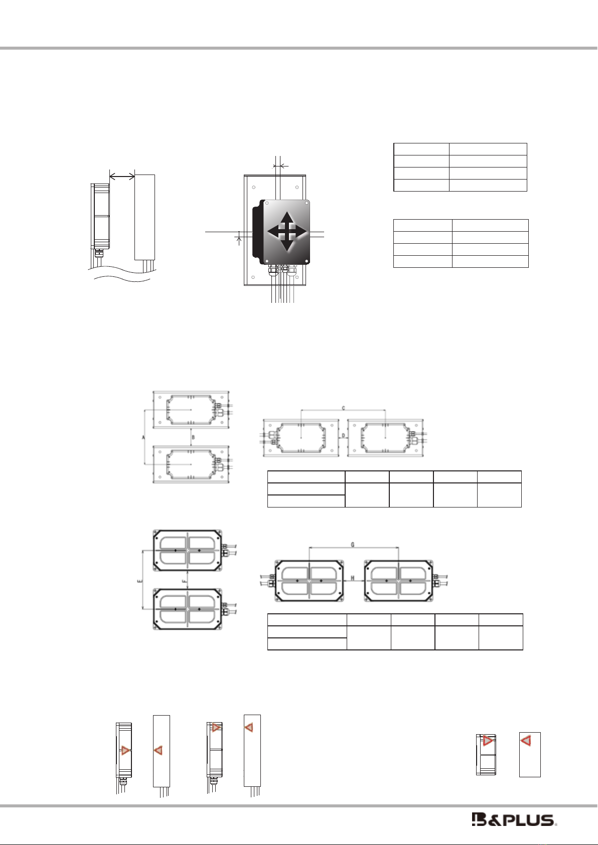
〇 Inuence of surrounding metal
To avoid inuence of surrounding metal, keep minimum spacing.
Also, please remove metal chips and cutting pieces on the transmission surface of the head part. Metal piec-
es may generate heat, which may result in damage to equipment or accidents. Therefore, install it so that the
metal does not face each other for a long time within the range outside the specications.
■ Active Head / RCS600-AH
Power supply unit Charging unit
■ Passive Head / RCS600-CH
A B C D E
Active Head
RCS600-AH
45 46
Passive Head
RCS600-CH
57.5 87 45
(mm)
non-metal non-metal
metal metal
F
F
F
F
G
金属
■給電ヘッド/RCS600-AH-L
■受電ヘッド/RCS600-CH-L
F G
Active Head
RCS600-AH-L
0 40
Passive Head
RCS600-CH-L
(mm)
■
Long Distance Specication Active Head
/ RCS600-AH-L
■
Long Distance Specication Passive Head
/ RCS600-CH-L
metal
4.Notes at the time of installation
(at the time of attachment)
Power supply unit and Charging unit
Heads
Since this product is a natural air cooling
system, in order to obtain a higher cooling eect,
please install the unit so that the installation
environment does not interfere with convection
and do not allow heat to build up.
Since this product uses a forced air cooling
system with a built-in fan, take care to ensure
that the air intake and exhaust ports are not
blocked, and that the installation environment
of the unit does not hinder convection so that
heat does not accumulate.
- 13 -
Wireless charging system 600W specication
For 12V・24V・48V battery
G
X 軸方向
Y 軸方向
X 軸方向
Y 軸方向
X 軸方向
Y 軸方向
〇 For the transmission distance and center o-set between the heads
Set the allowable misalignment of the passive head and the active head within the following ranges.
If the product is used outside the range, you may or equipment degradation of transmission eciency may be
damaged. Also, it is not possible to combine a standard head and a long distance head.
Direction Distance
G 0 ~ 20mm
X ± 10mm
Y ± 15mm
X direction
Y direction Direction Distance
G 20 ~ 40mm
X ± 10mm
Y ± 20mm
■
Long Distance Specication Head
* The total axis misalignment
of XY for long distance
specications is up to 20mm.
■
Standard Specication Head
■
Standard Specication Head
Type code A B C D
RCS600-AH 170 45 300 46
RCS600-CH
・Mutual Interference between the heads
If you are installing in parallel head, to avoid the eects of mutual interference, please attach the
head with an interval greater than or equal to the value shown in the table below always.
■
Long Distance Specication Head
Type code E F G H
RCS600-AH-L 190 40 290 40
RCS600-CH-L
(mm)
(mm)
〇 Positioning label
Positioning label is included for head positioning.
An example of pasting is shown, so please use it if necessary.
【Side view】 【Top view】

- 14 -
Wireless charging system 600W specication
For 12V・24V・48V battery
R bending of the head and the cable line
Please make the following is greater than
or equal to the number of R(mm) bending of the cable line.
・Active Cable and Passive Cable : R50
・Signal Cable line : R30
〇 Installation of ferrite clamp
For details, see P.18 ~ P.20
Reference example
◆ Filter(Type:
RCS-FILTER01
)
This is a filter for the RCS600-AC. Please use it by
attaching it to the air intake section.
A separate instruction manual is available. (No.T320403)
<Maintenance>
The cooling fan and power switch may require maintenance depending on the operating environment
and frequency of use. If you notice any abnormality when using the product, please contact us.
Also, to reduce dust/mist, attach the lter included with the power supply unit to the air inlet of the
power supply unit. The filter should be inspected periodically, and if any clogging, deterioration, or
contamination is observed, the lter should be replaced immediately. If the lter becomes dirty, not
enough air can be taken in, which may cause malfunction or re. For replacement lters, see P.25 in the
section "9. Included and Optional Accessories".
Filter
8pcs. included
24pcs. for optional purchases
installation image
Tape
8pcs. included
8pcs. for optional purchases
Tape
Filter
Both sides need to be attachd
5. Maintenance
R
■ Daily inspection
Inspection point Inspection details Inspection method
Inspection of each device
・Power connector
・Each terminal block of the Charging unit
· Connectors between devices
・ LED lighting
·others
Whether there are any damaged parts
Whether the screws have fallen o
Whether the wiring is connected correctly
Whether there is any abnormal noise
Whether there is odor
Whether the connector is properly
connected
Whether an abnormality has occurred
Please check by sight, sound and smell.
Presence or absence of metal foreign matter
besides the active head or passive head
Whether there is any metallic foreign
matter between and around the head Please check by sight.
Error indication LED lighting Whether Error, E1 to E3 are not lit Please check by sight.
Power supply cooling fan operation Wether it is operating without noise Please check by sight and sound.

- 15 -
Wireless charging system 600W specication
For 12V・24V・48V battery
Name Function Display Output
Power Display main power supply Lit green Present
Ready
Displayed in the stopped charging state
(charging standby state)
Lit blue Present
Charge Displaying during constant current
or voltage charge operation Lit orange Present
End Display the end of charging Lit green Present
Error Indicates abnormality Lit red Present
Error code Display abnormal contents by com-
bination E1 ~ E3. Lit red Present
For details on how to identify and deal with abnormalities, please refer
to “Identifying and Troubleshooting Abnormalities” on page 28.
〇 Connector specication 〇
If necessary, the followings
are recommended.
Connector: D-sub 25 pin (male)
Soldering type:HDBB-25P (05) Hirose Electric
Case made by HDB-CTH Hirose Electric
Terminal block type:SUBCON 25M-SH made by Phoenix Contact
Protective cap:DB-25S-DC1 Hirose Electric
Mounting screw: M2.6 (mm screw)
6.LED/IO connector for each units
Power supply unit(RCS600-AC)
I/O connector
LED output display
Output signal circuit diagram
Fitting surface of connector (cable wiring side)
13 12 11 10 9 8 7 6 5 4 3 2 1
25 24 23 22 21 20 19 18 17 16 15 14
L
O
A
D
18 17 16 8 7 6 5 4
DC 24V
power
supply
-
+
20
* Both NPN and PNP can be wired.The gure is an example of NPN wiring.
L
O
A
D
L
O
A
D
L
O
A
D
L
O
A
D
L
O
A
D
L
O
A
D
L
O
A
D
Pin.
Pin.
Charge
End
Error
電源ユニットのみ
Power
電源ユニット側
Input
Input signal schematic
Output signal schematic
external
external
internal
internal
dry contact
ca.2mA
Pin.14
Pin.1
2k Ω
2k Ω
5V
Output
(Only for Power supply unit)
Power
less than
50mA
4
5
39V
39V
39V
6
7
8
16
17
18
39V
39V
39V
39V
39V
39V
Ready
Charge
End
Error
E1
E2
E3
less than30V
20
無電圧接点
Pin.
Pin.
Charge
End
Error
電源ユニットのみ
Power
External output
signal
Ready
Power
Charge
Error
E1
E2
E3
End
■ Periodic inspection
Inspection point Inspection details Inspection method
All units (once/year)
Check for looseness and missing screws, bolts, nuts, etc.
Whether dust has accumulated on each device
Check visually and retighten.
Battery inspection (at least 1-2
times/year) Whether the battery has deteriorated
Check according to the battery manufacturer's
instruction manual or specications.
Check the cooling status of the
power supply unit
(1-2 times or more/year)
Whether the slits of the inlet or exhaust port are
clogged with dust, etc..
Whether foreign matter is attached
Whether the cooling fan is working without abnormal noise
Please check visually, sound, and airow,
and if necessary, clean or replace (consult
with our person in charge).
Check if the charging unit output
setting is the specied value
(twice/year)
Check the charging voltage/current settings Measure with a voltmeter and ammeter at
the charging unit output terminals.
Check the usage conditions
(at least 1-2 times/year)
Whether the transmission distance between heads uctuates
greatly (is it within the transmission distance range?)
Check whether the cooling function has deteriorated due to
accumulation of dust, etc. around the equipment.
Please check visually, with a distance meter, etc.
If there is a problem, please adjust and clean

- 16 -
Wireless charging system 600W specication
For 12V・24V・48V battery
Charging unit (RCS600(B)-CA _)
LED output
I/O connector
Name Function Display method Output
Ready
Displayed in the stopped charging
state (charging standby state)
Lit Blue Present
Charge Displaying during constant current
or voltage charge operation
Lit Orange Present
End Display the end of charging Lit Green Present
Error Indicates abnormality Lit in Red Present
Error code Display abnormal contents by com-
bination E1 ~ E3.
Lit in Red Present
For details on how to identify and deal with abnormalities, please refer
to “Identifying and Troubleshooting Abnormalities” on page 28.
normal open type: When you connect Pin 1 and Pin 14, charging will start.Since the charging unit does not operate (charge) unless Pin 1 and Pin 14 are connected, use
the attached Dsub25P start signal ON connector, or turn it ON separately by wiring or on the control side.
normal close type: Since Pin 1 and Pin 14 are connected in advance, charging will start when the power is turned on and the heads are properly facing each other.
Fitting surface of connector (cable wiring side)
Normal open type Normal close type
13 12 11 10 9 8 7 6 5 4 3 2 1
25 24 23 22 21 20 19 18 17 16 15 14
Dry contact
charging OFF charging ON
18 17 16 8 7 6 5
-
+
20
114
* Both NPN and PNP can be wired.The gure is an example of NPN wiring.
For PNP, + and - are reversed.
External
input
signal
Fitting surface of connector (cable wiring side)
Ready
Ready
Charge
Charge
Error
Error
E1
E1
E2
E2
E3
E3
End
End
External
output
signal
DC 24V
power
supply L
O
A
D
L
O
A
D
L
O
A
D
L
O
A
D
L
O
A
D
L
O
A
D
L
O
A
D
13 12 11 10 9 8 7 6 5 4 3 2 1
25 24 23 22 21 20 19 18 17 16 15 14
18 17 16 8 7 6 5
-
+
20
114
External
input
signal
Dry contact
charging ON charging OFF
* Both NPN and PNP can be wired.The gure is an example of NPN wiring.
For PNP, + and - are reversed.
DC 24V
power
supply
External
output
signal
L
O
A
D
L
O
A
D
L
O
A
D
L
O
A
D
L
O
A
D
L
O
A
D
L
O
A
D
Name Function Pin No. Remark
Power ON with power supply 4,20 Output
Ready ON when charging is stopped
(charging standby state) 5,20 Output
Charge
ON during constant current or con-
stant voltage charge operation
6,20 Output
End ON at the end of charging 7,20 Output
Error ON when abnormal 8,20 Output
E1
E2
E3
The abnormality are indicated by LED
lighting combinations of E1 to E3
16,20
17,20
18,20
Output
I/O connector function
The operation status of the power supply unit is output to
the outside at the same time as the LED display.
As for the operation of the output signal, the output
turns ON when the LED lights up. Each output is an
open collector output circuit with a rated voltage of 24V
and a maximum current of 50mA. Built-in output surge
absorption protection circuit (maximum 39V).
* Do not wire in combinations other than those listed in "I/
O connector functions" above. Wiring to pins other than
those listed above may result in malfunction.
Type code
Normal open Normal close
12V type RCS600-CA12 RCS600B-CA12
24V type RCS600-CA24 RCS600B-CA24
48V type RCS600-CA48 RCS600B-CA48
RCS600B
CA
12
RCS600B
CA
24
RCS600B
CA
48
RCS600
CA
12
RCS600
CA
24
RCS600
CA
48

- 17 -
Wireless charging system 600W specication
For 12V・24V・48V battery
Pin.
Pin.
Charge
End
Error
電源ユニットのみ
Power
電源ユニット側
Input
Input signal schematic
Output signal schematic
external
external
internal
internal
dry contact
ca.2mA
Pin.14
Pin.1
2k Ω
2k Ω
5V
Output
(Only for Power supply unit)
Power
less than
50mA
4
5
39V
39V
39V
6
7
8
16
17
18
39V
39V
39V
39V
39V
39V
Ready
Charge
End
Error
E1
E2
E3
less than30V
20
無電圧接点
Pin.
Pin.
Charge
End
Error
電源ユニットのみ
Power
Pin.
Pin.
Charge
End
Error
電源ユニットのみ
Power
電源ユニット側
Input
Input signal schematic
Output signal schematic
external
external
internal
internal
dry contact
ca.2mA
Pin.14
Pin.1
2k Ω
2k Ω
5V
Output
(Only for Power supply unit)
Power
less than
50mA
4
5
39V
39V
39V
6
7
8
16
17
18
39V
39V
39V
39V
39V
39V
Ready
Charge
End
Error
E1
E2
E3
less than30V
20
無電圧接点
Pin.
Pin.
Charge
End
Error
電源ユニットのみ
Power
Name Function
Pin No.
Remark
Charge start sig-
nal(activation signal)
dry contact ON: start charging
dry contact OFF: stop charging 1,14 Input
Charge stop signal
dry contact ON: stop charging
dry contact OFF: start charging
Ready Displayed in the stopped charging
state (charging standby state) 5,20 Output
Charge
ON during constant current or
constant voltage charge operation
6,20 Output
End Turn on when charging ends 7,20 Output
Error ON when abnormal 8,20 Output
E1
E2
E3
The abnormality are indicated by
LED lighting combinations of E1 to
E3
16,20
17,20
18,20
Output
I / O connector function
The operation status of the charging unit is output to the outside simultaneously with the LED indicates
The operation of the output signal turns ON when the LED is lit.
In the output circuit, rated voltage 24 V rated current 50 mA, only surge protection (39 V) is installed.
Parameter setting of charging current · charging voltage · timer is done by connecting dedicated connector to PC
and launching dedicated software
※ The followings are recommended for the Dsub 25 pin
plug side if it is prepared by the customer.
HDBB-25P (05) Hirose Electric Machine
Case:HDB-CTH Hirose Electric Case
Terminal block type:SUBCON 25M-SH made
by Phoenix Contact
Input circuit specications
Items Specication
Type code
RCS600-CA__ RCS600B-CA__
Contact Dry contact
(Normal open type)
Dry contact
(Normal close type)
Pin.1 Start charging Stop charging
Rated voltage 5V 5V
Rated current About 2mA About 2mA
Input
Output
■ Wiring of start signal of charging unit
内部回路
Pin1. 充電開始
Pin14.GND
無電圧接点
A 接点仕様
内部回路
Pin1. 充電停止
Pin14.GND
無電圧接点
B 接点仕様
Internal circuit
Internal circuit
dry contact dry contact
chrage start
normal open normal close
chrage stop

- 18 -
Wireless charging system 600W specication
For 12V・24V・48V battery
BATT
12V
+ -
BATT
12V
+ -
AC 90~220V
受電ヘッド
RCS600-CH
給電ヘッド
RCS600-AH
電源ユニット
RCS600-AC
■充電ユニット
・RCS600-CA24(24V仕様)
・RCS600-CA12(12V仕様)
・RCS600-CA48(48V仕様)
サーミスタ
※バッテリは各仕様による
24V仕様・・・12V x 2(直列)
12V仕様・・・12V x 1
48V仕様・・・12V x 4(直列)
E04SR401938
(フェライトコア)
2T/100mm以内
RFC-H13
(フェライトコア)
2T/100mm以内
RFC-H13
(フェライトコア)
2T/100mm以内
E04SR401938
(フェライトコア)
2T/100mm以内
フェライトコア付き
電源ケーブル
Dsub25P起動信号ON用
コネクタ
RCS600-OP001
- 3 -
図 1 全体構成図(標準仕様)
図 2 全体構成図(長距離仕様)
Ferrite clamp
Within 2T/100mm
※3
Common to standard specication heads and long distance specication heads
· Turn on the power after completing the wiring.
· Battery and charging cable are not included in this product. Please prepare and process by customer.
· Make sure that the ends of the charging cable do not touch each other.
· Please be sure to attach the thermistor to the attached parts. It is recommended to paste on the upper part of
battery. Please do not touch it the terminal
· Connect each cable with the specied length. There is a possibility that an error may occur due to output reduction
or the like.
・The "turn", which counts the number of turns of the ferrite clamp of each cable, indicates the number of times that
the cable passes through the inside of the ferrite clamp.
For example, if it is wrapped around the ferrite clamp once, it will take 2 turns, and if it passes through the cable
without wrapping it once, it will take 1 turn.
Standard Specication Head
2T=2 ターン
※ 2 Charging cable is not included.
A cable of 5.5 sq or more is recommended.
Dsub25P 起動信号 ON 用
コネクタ
型式:RCS600-OP001
※2
※1
RCS600
CA
12
RCS600
CA
24
RCS600
CA
48
2T
2T
Charging unit
RCS600(B)-CA12(12V)
RCS600(B)-CA24(24V)
RCS600(B)-CA48(48V)
Battery depends on each specication
12V type…12V × 1 24V type…12V × 2
(series)
48V type…12V × 4
(series)
2 turn
2 turns
2 turn
2 turn
Power cable with ferrite clamp
(Cable lenth 180cm - Included clamp)
Ferrite clamp
Within 2T/300mm ※ 3
AYCS-212 BK
Ferrite clamp
Ferrite clamp
Within 2T/100mm
※3
Within 2T/100mm
Connector for
power supply
Connector for
communication
RFC-H13
E04SR401938
Power Supply unit
RCS600-AC
Active Head
RCS600-AH
Passive Head
RCS600-CH
2T=2 turns
connector for
communication
connector for
power supply
Lead battery
or
Lithium Ion Battery
Thermistor
Type code:
RCS-THERM1.5
Battery
Dsub25P-Connector for
start signal ON
RCS-DSUB
※ 1 This is a D-sub connector in which PIN1 and PIN14 are
shorted circuit internally. When this connector is attached to
the charging unit, charging starts automatically when the head
is facing. (Required only for normal open type. Not required for
normal close type)
※ 3 Be sure to refer to “Installing the Ferrite clamp” on the
next page.
90 ~ 220V AC
(If you want to use it at AC200V,
you need to process the tip)
7.Connection diagram

- 19 -
Wireless charging system 600W specication
For 12V・24V・48V battery
BATT
12V
+ -
BATT
12V
+ -
AC 90~220V
受電ヘッド
RCS600-CH-L
給電ヘッド
RCS600-AH-L
電源ユニット
RCS600-AC
■充電ユニット
・RCS600-CA24(24V仕様)
・RCS600-CA12(12V仕様)
・RCS600-CA48(48V仕様)
サーミスタ
※バッテリ数は各仕様による
24V仕様・・・12V x 2(直列)
12V仕様・・・12V x 1
48V仕様・・・12V x 4(直列)
E04SR401938
(フェライトコア)
1T/100mm以内
E04SR401938
(フェライトコア)
100mm以内
フェライトコア付き
電源ケーブル
Dsub25P起動信号ON用
コネクタ
RCS600-OP001
RFC-H13
(フェライトコア)
2T/100mm以内
3T
2T
- 3 -
図 1 全体構成図(標準仕様)
図 2 全体構成図(長距離仕様)
Long distance Specication Head
※2
※1
※ About installing the Ferrite Clamp
In order to fulll the criteria of Article 65, paragraph 1, product 3 of the Radio Equipment Regulations, and
Ministry of Internal Aairs and Communications Notication 207, and malfunction preventionplease attach
the enclosed ferrite clamp to the following positions with specied turns each.
Case for standard specication head
· 1piece to the communication cable of the passive head within 100 mm from the charging unit. (2 turns)
· 1piece each to the power supply cable and communication cable of the active head within 100 mm from
the power supply unit. (2 turns)
· 1piece to the power supply cable within 300 mm from the power supply unit. (2 turns)(It is already installed
at the time of shipment)
Case for long distance specication heads (see gure above)
・ 1 piece from the charging unit to the battery within 100 mm (1 turn)
・ 1 piece to the communication cable of the active head within 100 mm from the power supply unit (2 turns)
・For the power cable, attach 1 piece of additional ferrite clamp included with the active head within 300
mm in addition to the one already installed at the time of shipment. (Refer to the gure above ※ 3)
※ When using each extension cables, install them on the unit side regardless of the head specications.
Please refer to the next page.
2T
3T
2T
3T
1T
RCS600
CA
12
RCS600
CA
24
RCS600
CA
48
※3
2 turns
3 turns
90 ~ 220V AC
(If you want to use it at AC200V, you need to
process the tip)
Power cable with ferrite clamp
(Cable lenth 180cm - Included clamp)
AYCS-212 BK
E04SR401938
( フェライトコアクラン
Ferrite clamp)
3T&2T/within 300mm
1turn
※ 2 Charging cable is not included.
A cable of 5.5 sq or more is recommended.
Battery depends on each specication
12V type…12V × 1 24V type…12V × 2
(series)
48V type…12V × 4
(series)
Lead battery
or
Lithium Ion Battery
Battery
Thermistor Type code:
RCS-THERM1.5
E04SR401938
Ferrite clamp
Within 1T/300mm
Charging unit
RCS600(B)-CA12(12V)
RCS600(B)-CA24(24V)
RCS600(B)-CA48(48V)
Dsub25P-Connector for
start signal ON
RCS-DSUB
※ 1 This is a D-sub connector in which PIN1 and PIN14 are
shorted circuit internally. When this connector is attached to
the charging unit, charging starts automatically when the head
is facing. (Required only for normal open type. Not required for
normal close type)
2 turns
1T=1 turn
2T=2 turns
3T=3 turns
RFC-H13
Ferrite clamp
Within 2T/100mm
Connector for power supply
Connector for
communication
Active Head
RCS600-AH-L
Passive Head
RCS600-CH-L
Power Supply unit
RCS600-AC

- 20 -
Wireless charging system 600W specication
For 12V・24V・48V battery
- 3 -
③
RCS600AH-PWN-***
RCS600AH-PWR-*** 給電ヘッド-電源側延長コネクタケーブル
④
- RCS600AH-SIR-*** 給電ヘッド-信号側延長コネクタケーブル
⑤
RFC-H13 分割フェライトコア(白)
⑥
E04SR401938 分割フェライトコア(灰)
図 1 全体構成図(標準仕様)
図 2 全体構成図(長距離仕様)
How to switch on a power
BATT
12V
+ -
BATT
12V
+ -
AC 90~220V
受電ヘッド
RCS600-CH
給電ヘッド
RCS600-AH
電源ユニット
RCS600-AC
■充電ユニット
・RCS600-CA24(24V仕様)
・RCS600-CA12(12V仕様)
・RCS600-CA48(48V仕様)
サーミスタ
※バッテリは各仕様による
24V仕様・・・12V x 2(直列)
12V仕様・・・12V x 1
48V仕様・・・12V x 4(直列)
E04SR401938
(フェライトコア)
2T/100mm以内
RFC-H13
(フェライトコア)
2T/100mm以内
RFC-H13
(フェライトコア)
2T/100mm以内
E04SR401938
(フェライトコア)
2T/100mm以内
フェライトコア付き
電源ケーブル
Dsub25P起動信号ON用
コネクタ
RCS600-OP001
※ For long distance specication head, it is not
necessary to install a ferrite clamp on the charging unit
side.
Ferrite clamp installation image when using various extension cables with the standard head
Ferrite clamp installation image when using various extension cables with long distance head
BATT
12V
+ -
BATT
12V
+ -
AC 90~220V
受電ヘッド
RCS600-CH
給電ヘッド
RCS600-AH
電源ユニット
RCS600-AC
■充電ユニット
・RCS600-CA24(24V仕様)
・RCS600-CA12(12V仕様)
・RCS600-CA48(48V仕様)
サーミスタ
※バッテリは各仕様による
24V仕様・・・12V x 2(直列)
12V仕様・・・12V x 1
48V仕様・・・12V x 4(直列)
E04SR401938
(フェライトコア)
2T/100mm以内
RFC-H13
(フェライトコア)
2T/100mm以内
RFC-H13
(フェライトコア)
2T/100mm以内
E04SR401938
(フェライトコア)
2T/100mm以内
フェライトコア付き
電源ケーブル
Dsub25P起動信号ON用
コネクタ
RCS600-OP001
Power Supply unit
RCS600-AC
Charging unit
RCS600(B)-CA _
BATT
12V
+ -
BATT
12V
+ -
AC 90~220V
受電ヘッド
RCS600-CH
給電ヘッド
RCS600-AH
電源ユニット
RCS600-AC
■充電ユニット
・RCS600-CA24(24V仕様)
・RCS600-CA12(12V仕様)
・RCS600-CA48(48V仕様)
サーミスタ
※バッテリは各仕様による
24V仕様・・・12V x 2(直列)
12V仕様・・・12V x 1
48V仕様・・・12V x 4(直列)
E04SR401938
(フェライトコア)
2T/100mm以内
RFC-H13
(フェライトコア)
2T/100mm以内
RFC-H13
(フェライトコア)
2T/100mm以内
E04SR401938
(フェライトコア)
2T/100mm以内
フェライトコア付き
電源ケーブル
Dsub25P起動信号ON用
コネクタ
RCS600-OP001
Attach the Ferrite clamp to
the unit side
E04SR401938
(
Ferrite clamp
)
Within 2T/100mm
connector for
power supply
connector for
communication
RFC-H13
(
Ferrite clamp
)
Within 2T/100mm
connector for
power supply
RFC-H13
(
Ferrite clamp
)
Within 2T/100mm
connector for
communication
Passive Head
RCS600-CH
Active Head
RCS600-AH
Attach the ferrite clamp
to the unit side
connector for
power supply
Power Supply unit
RCS600-AC
connector for
communication
RFC-H13
(
Ferrite clamp
)
Within 2T/100mm
Active Head
RCS600-AH
2T=2 turns
Refer to the photo on the previous page
(P.18-20) for the winding image of the
ferrite clamp.
Turn on the power switch on the back of the power supply unit. (Pressing the switch to the ON side will turn it “on”.)
・When active and passive heads are out of transmission range:
When the power is turned on, LED of the power supply unit (Power) is lit, it will be intermittent oscillation state.
· When active and passive heads are within transmission range:
When the power is turned on, LED of the power supply unit (Power) is lit, and immediately the LED (Ready) turns on.
(However, for normal open type, charging will not start if the charge start signal is OFF.)
Then (Ready) turns o, (Charge) lights and becomes charging state.
How to turn o the power
Turn o the power switch on the back of the power supply unit. (Pressing the switch in the opposite direction to
the ON side will turn it o.)
・When active and passive heads are within transmission range : When the power is turned o, the LED (Power) of
the power supply unit turns o after several tens of seconds and the operation is stopped.
· When active and passive heads are within transmission range : Charging will stop as soon as the power is turned
o. The LED of the power supply unit and the LED of the charging unit will all turn o after a few seconds, and the
operation will be stopped. (Depending on the state of the LED that is lit, the time until it is completely turned o
changes from a few seconds to a few tens of seconds.)
When active head and passive heads are within the range, when the power can be transmitted
charging Immediately.
Attention
8.Operation methods
Other manuals for RCS600
2
This manual suits for next models
1
Table of contents
Other B&PLUS Batteries Charger manuals


