B&PLUS RCS Series User manual

Issue 2019.03.13
No. T313401Me
M
Thank you very much for purchasing the Wireless charging system RCS210 of B&PLUS lately.
Before using this Processor, read this manual carefully and operate properly, paying attention to the
safety aspects.
Wireless charging system
210W specication Manual
RCS series

For safety precautions
Please read, please use it correctly and full attention to safety this "Safety Precautions" before use.
Incorrect handling may cause not only malfunction or failure, leading to an accident or injury.
Also in order to prevent damage or injury, please look after.
■ About Warnings
You are viewing mark with the following notes on safety in this manual.
It indicates that there is likely to ignore this display, and operate the product
in an improper manner, serious injury or possible person to death.
If you ignore the display, and operate the product in an improper manner, it
indicates that that there is a possibility that people bear the damage, the po-
tential and property damage may occur.
■ About designation
The symbol shown in the instruction manual and product, have the following meanings.
Shows the attention "Please be careful".
I shows that please without doing the "forbidden".
I indicates mandatory "Please always run".
Caution
Attention
Caution
I do not do the resolution and remodeling
Failure to do so may result in re, electric shock or malfunction. In addition, there is a risk
that can lead to serious injury.When I perform the resolution and remodeling, a guarantee
may not be received.
I do not use it as trouble and an abnormal state
Smoke, or in the case of such an abnormal state when abnormal noise or oensive smell is,
please stop using it immediately.The malfunction or electric shock , the cause of the re.
The equipment inside, do not insert foreign objects and water
Such as metal objects or combustible enters, and will be set to smoke or fire due to
short circuit or malfunction, re, electrical shock or other damage.
This product is a 24VDC lead battery-only power supply device
It can not be used in applications other than 24VDC battery charge. The malfunction or
cause of the re.
In accordance with the instructions, I will do the wiring and mounting
Please ensure proper procedure to street work. The malfunction or cause of the re.
Attention
Use the product so that its temperature does not exceed the specified temperature
range. Using the product out of the specication range may cause equipment failure
due to overheating.
If you want to dispose of this product, you will be disposed of as industrial waste
Please dispose of in accordance with waste disposal regulations specied.
Always, I want to use the specied parts and accessories
The malfunction or accident, the cause of the re.
I do not take any action in the hot-line state
If you want to support the installation, maintenance, and failure, after conrming that the
main circuit breaker (power board) is always out, please work. When working with hot-
state, there is a potential for electric shock.
I use the power supply as set forth in the specication always
If it is used in power outside of the specications such as a power in excess of the rated
voltage, there is a risk of overheating, re or malfunction.
To contact a specialized dealer or installation of equipment (installation), the wiring
Improper by doing installation work on your own, you will malfunction or an electrical
shock, the cause of the re.
Do not put your hands or metal objects between the coils during operation
There and heat generated by induction heating, the potential to catch re.
Do not install in a place that may be exposed to high temperature
When installed in a place such as hot air heater or direct sunlight directly, it could cause
a malfunction or re.
Do not block the cooling fan
Heat build up inside and cause malfunction or re.
Do not touch the high temperature part
Work for a while or immediately after operation, please do not touch the (power supply
unit, charging Unit, Head part) hot spots. Doing so could result in burns.
The product is for ussing indoors
This product is designed for indoor use. Please use it indoors.
The malfunction or accident, the cause of the re.

Request for use on
● This product, which is one of those high frequency utilization equipment of Radio Law,
In the case of useing in Japan, please apply for a permission application for high frequency
utilizaion equipment permission to Ministry of Internal Aairs and Communications.
In the case of using the product out side Japan, please take appropriate action after
conrming by yourself the standards and regulations to which the customer’s system should
conform.
● The control communication device that is installed in the product, there is no need for (diploma)
radio station authorization of the Minister so apply to “a weak radio station (weak radio equipment)”
to. However, please be careful on the occasion of the operation because it may aect medical
equipment and electronic equipment (such as pacemakers).
※ Specications subject to change without notice.
※ If there is a point of notice about the contents of this document, hope you'll give me your contact
us, thank you.

■ Index ■
1. Product summary ・・・・・・・・・・・・・・・・・・・・・・・・・・・・・
System conguration and product conguration ・・・・・・・・・・・・・ 6
2. Feature ・・・・・・・・・・・・・・・・・・・・・・・・・・・・・・・・・・・ 7
3. The name and specication of each part ・・・・・・・・・・・・・・・・・・ 8
4. Notes at the time of installation (at the time of attachment) ・・・・・・・・ 11
5. About the wiring ・・・・・・・・・・・・・・・・・・・・・・・・・・・・・・・ 13
Connection diagram ・・・・・・・・・・・・・・・・・・・・・・・・・・・ 15
6. Method of operation ・・・・・・・・・・・・・・・・・・・・・・・・・・・・・ 16
How to switch on a power supply ・・・・・・・・・・・・・・・・・・・・ 16
How to turn o the power ・・・・・・・・・・・・・・・・・・・・・・・・ 16
About basic charge ・・・・・・・・・・・・・・・・・・・・・・・・・・・ 16
Image behavior of the output voltage and current value ・・・・・・・・・ 17
Characteristic diagram ・・・・・・・・・・・・・・・・・・・・・・・・・・ 18
7. About the function ・・・・・・・・・・・・・・・・・・・・・・・・・・・・・ 19
Battery voltage monitor function ・・・・・・・・・・・・・・・・・・・・・ 21
About the battery voltage monitoring for charging ・・・・・・・・・・・・ 21
About the battery voltage monitoring for non-charging ・・・・・・・・・ 22
・6

- 6 -
Wireless charging system 210W specication
1.Product summary
Create a high frequency from an AC power source, along with the transmitting power in a non-con-
tact with the charge control circuit, this product is a revolutionary wireless charging system that
has at the same time signal communication function.
System conguration and product conguration
Battery voltage : 24V DC
Available lead batteries : charging current is a thing of 7A or more
Product typecode Description of each part
① Charging unit RCS210-PB24 ・Charge to a battery is performed.
・It monitors the battery voltage, 【voltage monitor signal H,
M, L】 as, and output control device that is connected to this
unit and passive head results.
・I will output to control external devices connected to this
unit and passive head, the information signal on the “oat
charging start”, “charging”, “battery error”.
②
Power Supply unit
RCS240-AC1 ・AC power supply is changed into high frequency.
・In response to the input signal【start-up signal】, and sup-
plies the high frequency to active head.
・I will output to an external control device inzone signal vari-
ous signals and the active head is received.
③ Passive Head RCS240PH ・The receiving power from the active head, and supplies
power to the charging unit.
・I can carry in a non-contact to the active head and a variety
of signal that is output from the charging unit.
④ Active Head RCS240AH ・By electromagnetic coupling method, in a non-contact,
make the power transmitted to the passive head.
・Receives various signals from the passive head, and then
transmitted to the power supply unit.
①②
③
Power Supply unit
Charging unit
Active headPassive head
Thermistor
24V
lead battery
External control device
External control device
AC power supply
Power supply
Signal communication
Start-up signal
④
Voltage monitor signal H,M,L
Float charging signal
Charging signal
Error signal
Inzone signal
Voltage monitor signal H,M,L
Float charging signal
Charging signal
Error signal
Temperature control
ferrite clamp

- 7 -
Wireless charging system 210W specication
System conguration and product conguration
2.Feature
● Signal transmission system and non-contact power transmission
The signal transmission and power transmission, because the electromagnetic coupling method, is car-
ried out in a non-contact, no problem glass-plastic even in the presence of the transmission space.
● Oscillation power control function
If you have a transmission area within the specied range within the active head / passive head, active
head will make the oscillation behavior by controlling so that the internal voltage is constant value.If not
in the transmission area is passive head, and it is the specications that make the intermittent oscilla-
tion. In the case in the transmission area is passive head, in zone LED on the power supply unit is lit, in
zone signal is output to the outside.
● Active head overtemperature protection
If the piece of metal was present in the transmission space oscillation operation of the active head,
internal heating of the active head exceeds a certain temperature due to its eect, it shifts to the inter-
mittent oscillation protection function is activated.
● Battery voltage monitor function
If you have the inzone passive head, [voltage monitor signal H, M, L] is output to the outside from the
charging unit and power supply unit according to the battery voltage.
If there is no inzone passive head, when you connect the power of the default from external control de-
vices that are connected to the charging unit to [voltage monitor request], [voltage monitor signal H, M, L]
is to the outside from the charging unit is output.
● Charging function
Charging of the battery, held at the CC / CV charging, full charge is virtually possible. It is determined
that the full charge charging voltage reaches a certain level or higher, and then start the oat charging.
● Charging voltage error detection function
If you turn on the power to connect the battery of an adaptive voltage other than by mistake, it does not
start charging.
● Battery reverse connection or non-connection (disconnection) detection function
If you connect to reverse the battery terminal by mistake, it does not start charging.In addition, if the ca-
ble leading to the battery for some reason is broken, I will cut o the charge.
● Overcurrent protection
If the charging current ows at least a certain charging, after continued for 1 minute wait state, and
then shut o the charge.
● Overvoltage protection
If the charging voltage is constant over during charging, after continued for 1 minute wait state, and
then shut o the charge.
● Battery overheating protection
Battery is more constant temperature, when it comes to constant temperature or below, after continued
for 1 minute wait state, and then shut o the charge.
- 8 -
Wireless charging system 210W specication
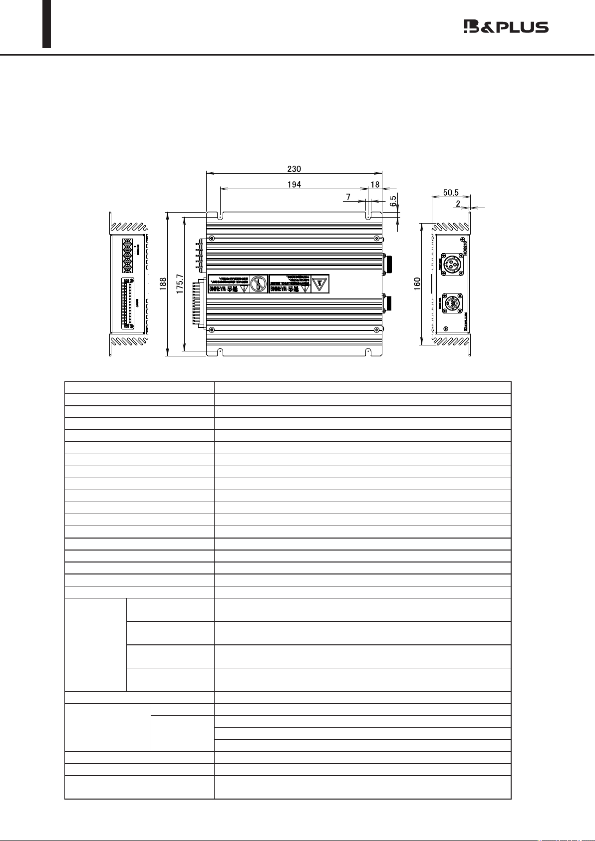
3.The name and specication of each part
● Charging unit
Type code RCS210-PB24
Application battery lead battery
Application passive head RCS240PH
Output voltage Max.30V (It varies depending on battery temperature)
Output current Max.7A
External input (5.About the wiring P.13 reference)
External output (5.About the wiring P.13 reference)
Operating temperature 0℃~ 40℃
Storage temperature 0℃~ 50℃
Operating humidity ≦ 90 %RH (No condensation)
Insulation ≧ 50M Ohm
Dielectric strength 1500 VAC / 1min
Shock rating 10G, each axis to x-y-z
Vibration rating 19.6m/sec2 (10 ~ 55Hz)
Protection class IP20
Dimension 230×188×50.5
Weight 1.6kg
Attachment hole dimensions 4-7x6.5
Connection Power supply
connector
Round 3-pin
Communication
connector
Round 5-pin
Terminal block Battery connection(2-pole), Thermistor connection(2-pole),
Terminal width 6.2mm or less, Terminal screw size M3
Various signal
connector
(5.About the wiring P.13 reference)
Cooling method Natural air cooling
Protection circuit Input Input overvoltage protection
Battery Battery high temperature / low temperature protection
Battery not connected protection
Battery reverse connection protection
Parallel driving None
Series driving Available
Accessories Output cable (1.5m), Thermistor with cable (1.5m),
External device communication connector, 4 screws M6x15

- 9 -
Wireless charging system 210W specication
● Power Supply unit
Type code RCS240-AC1
Apply active Head RCS240AH
Rated input voltage AC100V / AC200V
Power supply voltage AC85 ~ AC265V Single-phase 50/60Hz
Current consumption 4A
Display function The status display by LED
External input (5.About the wiring P.13 reference)
External output (5.About the wiring P.13 reference)
Operating temperature 0℃~ 50℃
Storage temperature 0℃~ 50℃
Operating humidity ≦ 90 %RH (No condensation)
Insulation ≧ 50M Ohm
Dielectric strength 1500 VAC / 1min
Shock rating 10G, each axis to x-y-z
Vibration rating 19.6m/sec2 (10 ~ 55Hz)
Protection class IP20
Dimension 300x210x80 (Including mounting portion)
Weight 2.7kg
Attachment hole dimensions 8-7x15
Connection Power supply
connector
Round 3-pin
Communication
connector
D-sub 9-pin
Power 3P inlet
Various signal
connector
(5.About the wiring P.13 reference)
Cooling method Forced air cooling
Accessories Power cable (2m), External device communication connector,
4 screws M6x15, One ferrite clamp
1
8-7X15
170
190
210
15 90 90 90 15 80
300

- 10 -
Wireless charging system 210W specication
● Head
Passive Head Active Head
Type code RCS240PH RCS240AH
Application power supply unit
/ charging unit
RCS210-PB24 RCS240-AC1
Application head RCS240AH RCS240PH
Rated gap Distance 10mm
Center o-set ≦ 10mm (4.Notes at the time of installation (at the time of at-
tachment) P.11 reference)
Operating temperature 0 ~ 50℃
Storage temperature -10 ~ 50℃
Operating humidity 30%~ 90%
Insulation ≧ 50M Ohm
Dielectric strength 2000 VAC / 1min
Shock rating 10G, each axis to x-y-z
Vibration rating 19.6m/sec2 (10 ~ 55Hz)
Protection class IP65
Dimension 140×100×40
Weight 1.3kg
Attachment hole dimensions 4- φ 6.5
Connection
(With the connector cable 1m)
Power : Connected to the Charging
unit at the (male) 3-pin round
Power : Connected to the Charging
unit at the (female) 3-pin round
Signal : Connected to the Charging
unit at the (male) D-sub9 pin
Signal : Connected to the Charging
unit at the (female) 5-pin round
Accessories 4 screws M6x15, One ferrite clamp
Passive Head
RCS240PH
Active Head
RCS240AH
126
86
担当
前島
リモートシステム
伝送部
■一般仕様
■外形寸法
前島
■特記事項
2016.06.29
1.本製品に対応した出力部の型式は、RCS240-AC1、RCS240AHです。
TA13504D
単位
尺度
図式
型式
管理番号
承認番号
作成日CODE/FILE
RCS240PH
1121110
1/2
mm
承認
B&PLUS K.K.
株式会社ビー・アンド・プラス
作成
型式:RCS240PH
製品仕様書
4-φ6.5
140
100
1000
8
40
126
86
RCS210-PB24
距離 10mm
軸ズレ ±10mm
0~50℃
-10~50℃
30%~90%
50MΩ以上
2000VAC 1分間
10G、XYZ方向に各11ms
19.6m/sec²(10~55Hz)、XYZ方向各20回
IP65(屋内設置型)
給電 丸形3ピン(メス)にて充電ユニットに接続
信号 丸形5ピン(メス)にて充電ユニットに接続
ヘッド PPS(G30%)、アルミ
出力ケーブル φ8.6 2.5mm²X3 KVU
信号ケーブル φ5.6 0.3mm²X4 PVC
1.3kg重量
材質
保護構造
適用充電ユニット
使用周囲温度
定格ギャップ
接続(コネクタ
ケーブル1m付)
耐振動
耐衝撃
保存周囲温度
周囲湿度
絶縁抵抗
耐電圧
126
86
前島
リモートシステム
出力部
■一般仕様
■外形寸法
■特記事項
前島
1.本製品に対応した伝送部の型式は、RCS210-PB24、RCS240PHです。
担当
TA13503D
単位
尺度
図式
型式
管理番号
承認番号
作成日CODE/FILE
RCS240AH
1121108
mm
1/2
作成 承認
B&PLUS K.K.
株式会社ビー・アンド・プラス
2016.06.29
型式:RCS240AH
製品仕様書
4-φ6.5
100
140
1000
8
40
126
86
RCS240-AC1
距離 10mm
軸ズレ ±10mm
0~50℃
-10~50℃
30%~90%
50MΩ以上
2000VAC 1分間
10G、XYZ方向に各11ms
19.6m/sec²(10~55Hz)、XYZ方向各20回
IP65(屋内設置型)
給電 丸形3ピン(オス)にて電源ユニットに接続
信号 D-sub9ピン(オス)にて電源ユニットに接続
ケース PPS(G30%)、アルミ
出力ケーブル φ8.6 2.5mm²X3 KVU
信号ケーブル φ5.6 0.3mm²X4 PVC
1.3kg
材質
重量
保護構造
適用電源ユニット
使用周囲温度
定格ギャップ
接続(コネクタ
ケーブル1m付)
耐振動
耐衝撃
保存周囲温度
周囲湿度
絶縁抵抗
耐電圧
- 11 -
Wireless charging system 210W specication
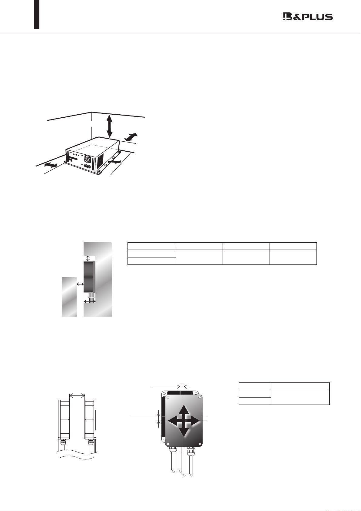
4.Notes at the time of installation (at the time of attachment)
● Notes at the time of installation of the charging unit and power supply unit
・Location
In order to obtain a good cooling eect, please keep as shown below the separation distance between
the surrounding body so as not to block the airow.
・For the transmission distance and center o-set between the heads
The permissible center o-set of the feed head and charging head, please be installed so that the to-
tal (X + Y) axis deviation of the width of the X-axis · Y-axis is the following table. (For example, X-axis
equals a 10mm, Y-axis 0mm. If X-axis is 5mm, Y-axis is less than 5mm.)
If the product is used outside the range, you may or equipment degradation of transmission eciency
may be damaged.
10cm以上
5cm以上
5cm以上
5cm以上
B B
軸ズレ XまたはYどちらか1方向 (mm)
A
B
C
Metal
Metal
GDirection Distance
G≦ 10mm
X+Y
X 軸方向
Y 軸方向
More than 5cm
More than 5cm More than 10cm
More than 5cm
X-axis direction
Y-axis
direction
● Notes of each head when mounting
・Inuence of surrounding metal
To avoid inuence of surrounding metal, keep minimum spacing.
Remove metal chips or metallic debris on the active surface.Metal chips or metallic debris generate
may damage to device or cause unexpected trouble.
Type code A(mm) B(mm) C(mm)
RCS240AH 100 40 45
RCS240PH

- 12 -
Wireless charging system 210W specication
・Mutual Interference between the heads
If you are installing in parallel head, to avoid the eects of mutual interference, please attach the
head with an interval greater than or equal to the value shown in the table below always.
・Head For R bending of the cable line
Please make the following is greater than or equal to the number of R(mm) bending of the cable line.
・Active Cable and Passive Cable : R50
・Signal Cable line : R30
Type code A(mm)
RCS240AH 300
RCS240PH
A
R
・Mounting of the ferrite clamp
Please refer to the P.15.
- 13 -
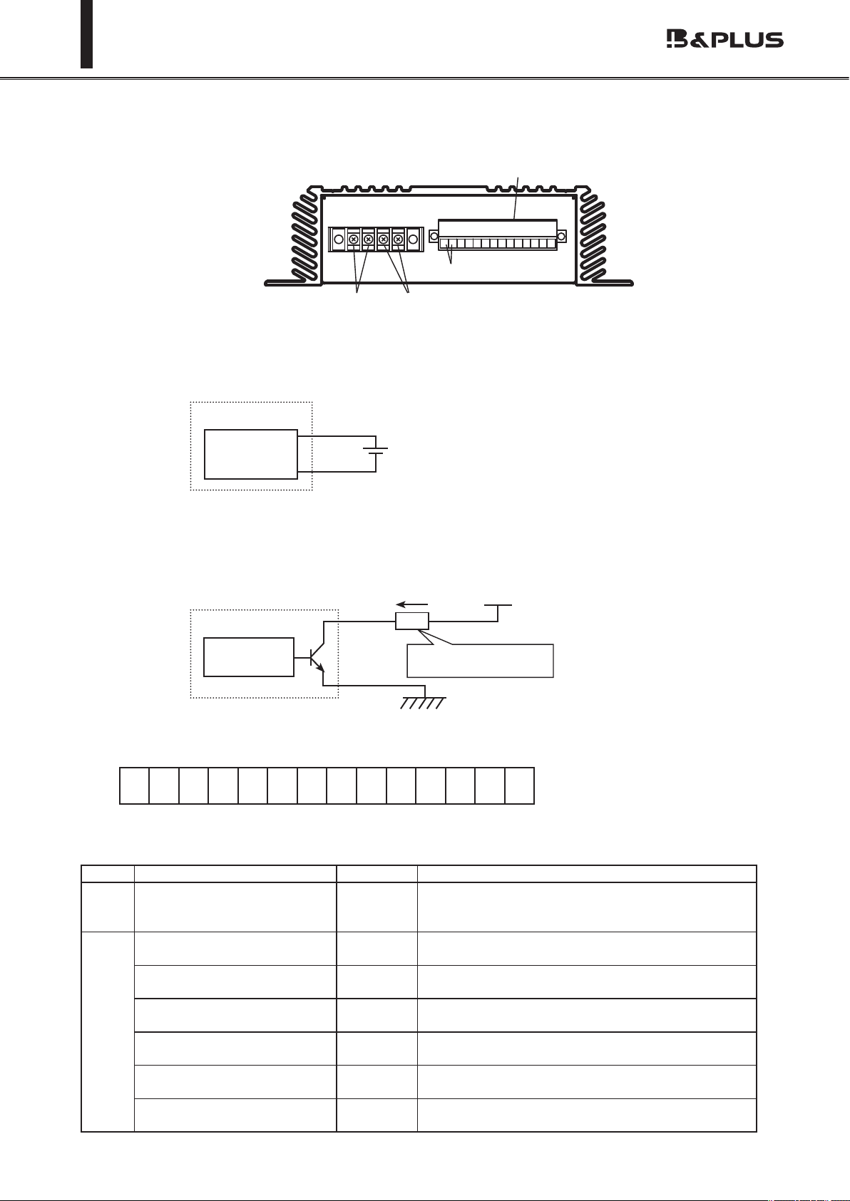
Wireless charging system 210W specication
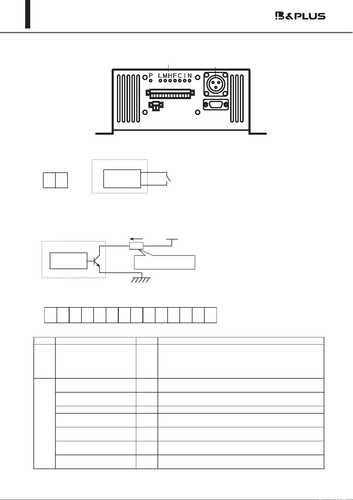
● Charging side (RCS210-PB24)
● Maximum load current : 5mA
● Maximum load voltage: 24V
②①
④
123456789
1011121314
③
① Output terminal for Battery
② Thermistor terminal
③ Input signal (voltage monitor request signal)
Other than at the time of charging, you can use if you want to output the battery voltage monitor signal.
④ Each output signal
Each output signal is an open connector.Please connect the load, such as not to exceed
the maximum load voltage and current of the following whenever you want to connect.
Please be careful so as not to short.
Signal type Pin number Contents
Input Voltage monitor request 1.2 It monitors the battery voltage and the voltage
applied to this pin, and the output voltage moni-
tor signal.
Output Voltage monitor signal H 3.4 It is almost fully charged. (Charging aim:about
90%)
Voltage monitor signal M 5.6 If the charge has been reduced somewhat.
(Charging aim:about 70%)
Voltage monitor signal L 7.8 It needs charging for charging amount is re-
duced. (Charging aim:less than about 50%)
Float charging signal 9.10 It turns on, when a charging current value turns
into a rated value.
Charging signal 11.12 I will turn OFF during charging ON, in charge cut-
o and oat charging start.
Error signal 13.14 It turns on, if a battery error occurs.
(7.About the function P.19 reference)
入力 24V 5mA
RM+ RM- BH+ BH- BM+
BM- BL+ BL- CHG
+
CHG-
FIN+
FIN-
ERR+
ERR-
L+L-
M+M-
H+H-F+F-C+C-N+N-
2 3 4 5 6 7 8 9 10 11 12 13 14
+-
5.About the wiring
Internal circuit
Charging unit
Vin
7.5 ~ 30V
Vcc
I
To t in each condition,
Please select the load
Load
〇+
〇-
Internal circuit
Charging unit
<Input signal pin assignment>
● Input current : 100mA
● Input voltage : 7.5V ~ 30V
1
- 14 -
Wireless charging system 210W specication
● Power supply unit side (RCS240-AC1)
PLMHFCIN
①
②
③
④
⑤
Signal type LED Contents
Input Start-up signal P Shorting this signal, make the power supply to the active
head.Then, the active head starts oscillating, and then
start the communication signal and power transmission
to the passive head. If you do not have a Passive head, I’ll
intermittent oscillation.
Output Voltage monitor signal L L It needs charging for charging amount is reduced.
(Charging aim:less than about 50%)
Voltage monitor signal M M If the charge has been reduced somewhat. (Charging
aim:about 70%)
Voltage monitor signal H H It is almost fully charged. (Charging aim:about 90%)
Float charging signal F It turns on, when a charging current value turns into a rat-
ed value.
Charging signal C I will turn OFF during charging ON, in charge cut-o and
oat charging start.
Inzone signal I I will if ON is in the transmission area within the Active
head / Passive head.
Error signal N It turns on, if a battery error occurs.
(7.About the function P.19 reference)
● Maximum load current : 50 m A
● Maximum load voltage: 30V
PS PS
ショートにて動作
P P
L+L-M+M-H+H-F+F-C+C-I+I-N+N-
1 2 3 4 5 6 7 8 9 10 11 12 13 14
① Connector for the active head (Signal)
② Connector for the active head (Power)
③ Start-up signal
④ Each output signal
Each output signal is an open connector.Please connect the load, such as not to exceed
the maximum load voltage and current of the following whenever you want to connect.
Please be careful so as not to short.
※ It is the ON / OFF signal of the power supply of the Active
Head.To do with the ON / OFF operation with separate
switch, please use always ON.
(It is a jumper with factory)
P
P
Internal circuit
Power supply unit
Vcc
I
To t in each condition,
Please select the load
Load
〇+
〇-
Internal circuit
Power supply unit
<Input signal pin assignment>
⑤ LED

- 15 -
Wireless charging system 210W specication
Single phase 100V,
200V
To the power supply
side
Power Supply unitCharging unit
(1)24V lead battery
(1) Parts of the dotted line (External device communication cable and 24V lead batteries) within the product
is not included with this product. They are contents prepared and processed of a visitor.
(2) That the protection function is turned on, is 40.5 ℃ or more. (The installation situation, there is a dier-
ence about ± 2 ℃ .)
In addition, I have you use the attached article always, thermistor put it on the side of 24V lead
batteries Please attach. In that case, please do not touch any terminal.
(3) Each cable, please connect with the specied length. You may receive an error due to the output such as
a decrease occurs.
Connection diagram
Passive Head Active Head
Power cable
Output cable
(2)Thermistor with Cable
(1)External
device commu-
nication cable
(AWG28 ~ 16)
(1)External device
communication cable
(AWG24 ~ 16)
Details of the charging unit input and output
24V
lead battery
Load
Thermistor
フェライトクランプ
フェライトクランプ
フェライト
クランプ
電源ユニット
充電ユニット
給電ヘッド受電ヘッド
Mounting of the ferrite clamp
The installation of the bundled ferrite clamp is necessary
in addition to the upper gure to meet a standard of the
EMC(IEC61000-4-3).
Please attach a ferrite clamp to a power cable by 2 turns
with the following points each.
・It is one within 20cm from a power supply unit
・It is one within 20cm from a power supply unit to the
power cable of the
active head.
・It is one within 20cm from a passive head to the power
cable of the passive head.
Charging
unit
Power
Supply
unit
Passive Head Active Head
ferrite clamp
ferrite clamp
ferrite
clamp
- 16 -
Wireless charging system 210W specication
6.Method of operation
I turn on the power switch on the power supply unit back. (It becomes the "On" and press the
switch to the white dot side)
・Active head and Passive head, when the power transmission coverage area:
When the power is turned on, LED of the power supply unit (P) is lit, it will be intermittent oscilla-
tion state.
・Active head and Passive head, when the power can be transmitted within the range:
When the power is turned on, LED power supply unit (P)(L)(M)(H)(F)(I) is lit.Then, (L)(M)(H) ashes,
(F) becomes OFF state, (C) is lit, it will be charged.
Active head and Passive head, when the power can be transmitted within the range, When
you press the power switch, will start charging Immediately. Please note.
Attention
How to switch on a power supply
How to turn o the power
About basic charge
I turn off the power switch on the power supply unit back. (It becomes the "Off" and press the
switch to the white dot side)
・Active head and Passive head, when the power transmission coverage area:
When the power is turned o, LED(P) of power supply unit turns o after about 10 seconds, the
operation stopped.
・A and B, when the power can be transmitted within the range:
When the power is turned o, LED of power supply unit is All o after a few seconds, the operation
stopped.(LED lit depends on the state.)
I will explain the non-contact power supply operation ow of the unit.
① When you turn on the power supply unit will cause the system (intermittent oscillation) wait
state. Rise time is about 5 seconds.
② The power can be transmitted within the scope of the (transmission side), and a state in which
there is a (receiving side) passive head, communication device passive head and power supply
starts to communication, to start the power transmission Active head. (Communication and power
transmission,is performed by non-contact.)
③ The charge control, I will do CC · CV control in . (Refer to the next section “Image behavior of
the output voltage and current value”)
④ It becomes oat charge state charging current drops to 1.5A battery voltage and reached a
predetermined voltage. Also, stop the feeding automatically and goes into standby mode if Pas-
sive head became Active head power transmission coverage area.
⑤ Return to the CV charge state when the oat charging state, the output current becomes 3A,
it does the above.

- 17 -
Wireless charging system 210W specication
Image behavior of the output voltage and current value
(Operating to charging current 1.5A)
( )
V
(
V
)
充電時
I
(
A
)
7
充電時
( )
Output voltage
Output current
Output current 1.5A reach
Float charging time
CC charging time
CV charging
time
CV charging
time
Float charging time
CC charging time
- 18 -
Wireless charging system 210W specication
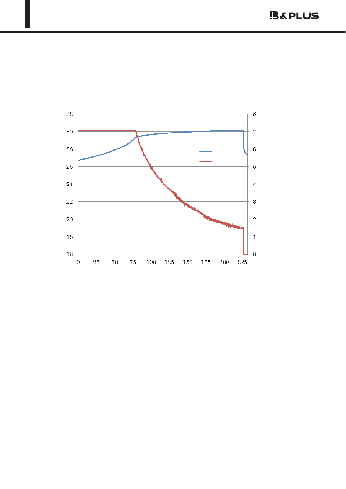
30Ah (5 hour rate) Battery discharge about 50%
Characteristics (Reference)
CC · CV charging characteristics
Time (minutes)
voltage
current
Charging current
(A)
Charging voltage
(V)
- 19 -
Wireless charging system 210W specication
・As a display function, I can be found in the LED displays the status of the equipment.
・As a protective function, it has the ability to detect abnormalities such as overheating during
charging.In that case, you can operate the protection circuitry to protect the equipment.
・It is equipped with a communication function, it performs radio communication with charging side be-
tween the power supply side, we are state control and charging.
The following shows the contents of the <display function> ... <protection>.
※ If an abnormality is detected, the unit will stop the charging operation.
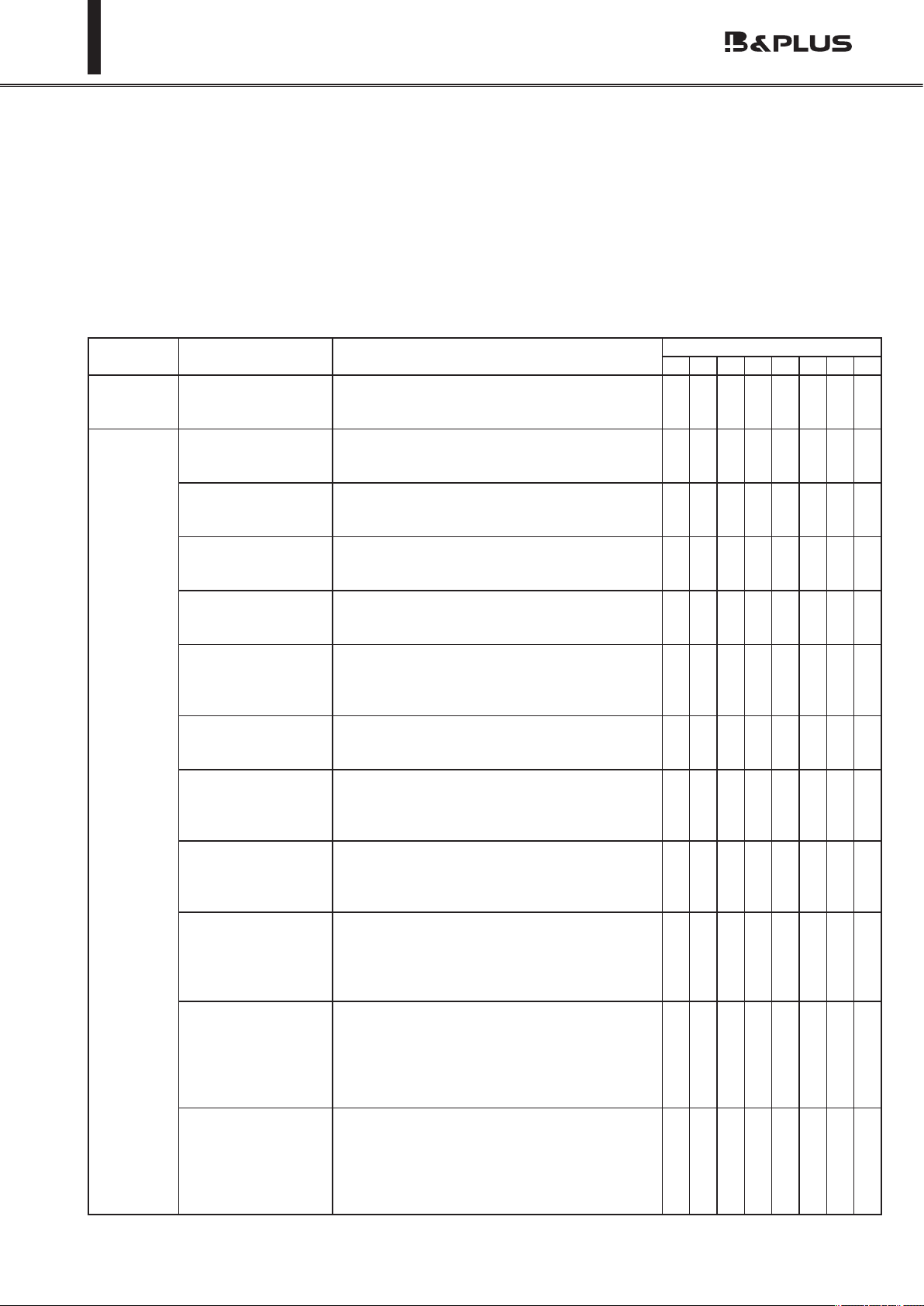
7.About the function
State of equipment Display content LED display
P L M H F C I N
Head
Non-combat
time
Intermittent oscilla-
tion state
This is a state in which power have been
turned on to the power unit, passive head is
not in the operating area of the active head.
●
Head
against
time
State of charge (L) Is charging.
(Charging aim:less than about 50%) ● ● ● ●
State of charge (M) Is charging.
(Charging aim:about 70%) ● ● ● ●
State of charge (H) Is charging.
(Charging aim:about 90%) ● ● ● ●
Float charging state If the charge current value becomes below
a specied value, I will move to this mode. ● ● ● ●
Charging voltage
error
Battery voltage outside of adaptation have
been connected, the voltage of the battery
is down to abnormal. Please connect the
correct battery.
● ● ● ●
Battery reverse con-
nection or non-con-
nection error
Battery terminal is turned in reverse, cable
is disconnected. Please check terminal, the
cable.
● ● ● ●
Over current error
Charging current was increased abnormally.
(8A or more) Since there is a possibility of
equipment failure, you must have inspection
and repair.
● ● ● ●
Over voltage error
Charging voltage was increased abnormally.
(About 33.5V or more) Since there is a pos-
sibility of equipment failure, you must have
inspection and repair.
● ● ● ● ●
Battery overheating
Battery is now the outside temperature
specication. (Specication temperature =
0 ℃ ~ 40 ℃ ). Please review the ambient
temperature environment of the battery.
Or, thermistor is disconnected.
● ● ● ● ●
Input voltage error
Input voltage from the passive head is ab-
normal. Please check distance and center
o-set between the heads is entering spec-
ications within. If you are still unable to
resolve the problem, there is a possibility of
equipment failure.
●●●● ●●
Head overheating
Head temperature has become used to
the maximum temperature (80 ℃ ) or more.
Please on the power again after cooling the
heat. If you are still unable to resolve the
problem, there is a possibility of equipment
failure.
●

- 20 -
Wireless charging system 210W specication
[How to reset body]
Reset can be done in one of the following methods.
・Turn OFF the power, turn ON after about a minute. (Restart)
・The 200mm or more away the head, and to face again in about one minute.
・The (OFF contact) OFF the start-up signal. After about 1 minute, turns ON the start-up signal.
<Communication function>
Communication machine is equipped with the passive head and active head of the unit.
Performs wireless communication with the communication unit, we are charging control and state con-
trol of the battery.
Other manuals for RCS Series
1
Table of contents
Other B&PLUS Batteries Charger manuals


