B&PLUS RCS600 User manual

発行 2021 年 4 月 26 日
No. T 318C05Ke
K
ThankyouverymuchforpurchasingtheWirelesschargingsystemRCS600ofB&PLUS.
Pleasereadtheinstructionmanualbeforeuseandpleaseusetheproductscorrectly.
Wirelesschargingsystem
600WspecicationManual
RCS600for12V,24V,48Vbattery
Standardhead,Longdistancehead
Standardhead
Longdistancehead

Forsafetyprecautions
Pleaseread,pleaseuseitcorrectlyandfullattentiontosafetythis"SafetyPrecautions"beforeuse.
Incorrecthandlingmaycausenotonlymalfunctionorfailure,leadingtoanaccidentorinjury.
Alsoinordertopreventdamageorinjury,pleaselookafter.
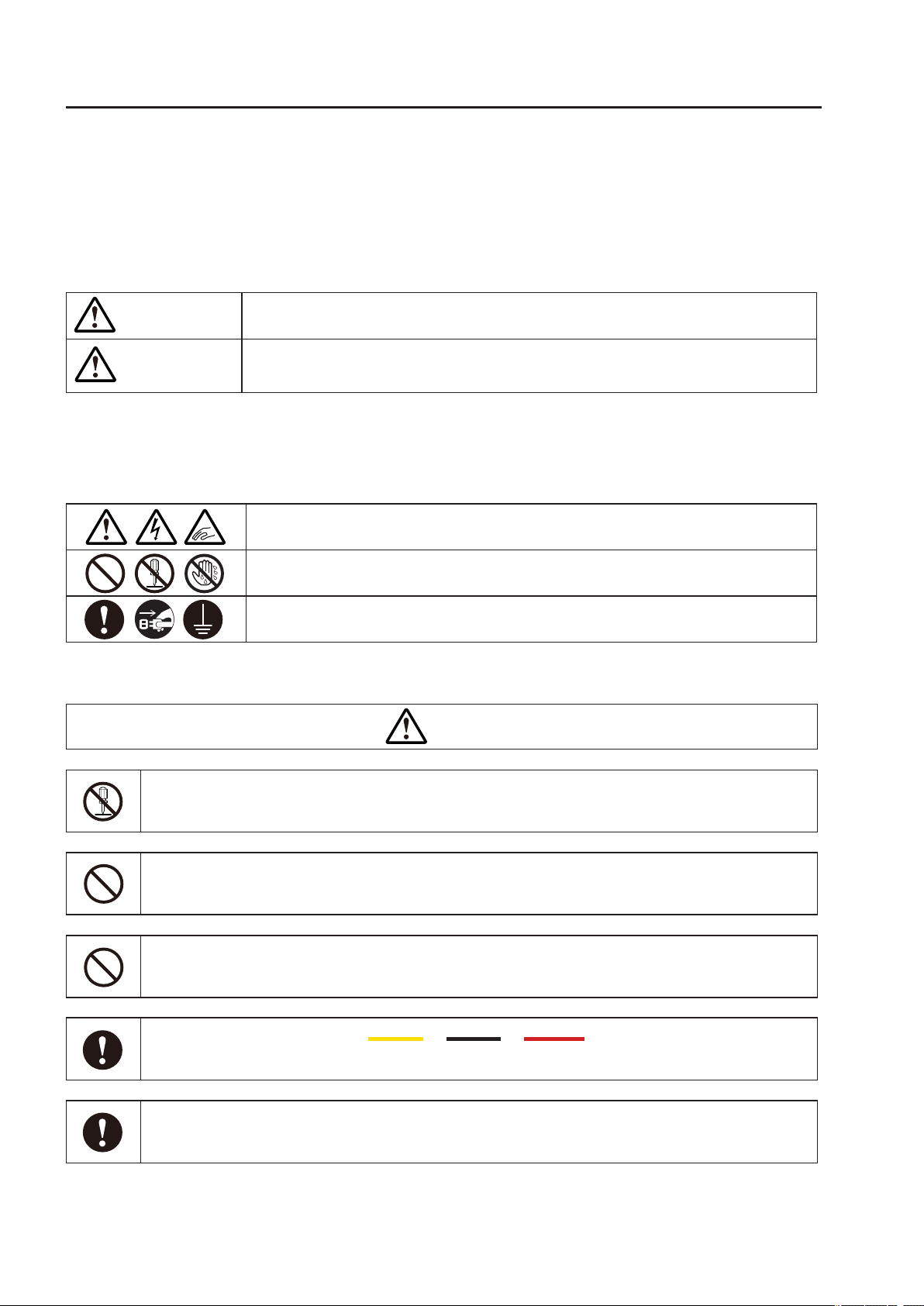
■ AboutWarnings
Youareviewingmarkwiththefollowingnotesonsafetyinthismanual.
Itindicatesthatifignoringthisdisplay,andoperatetheproductinan
impropermanner,seriousinjuryorpossibledeathcanoccur.
Ifyouignorethedisplay,andoperatetheproductinanimpropermanner,it
indicatesthatthereisapossibilitythatpeoplebearthedamage,thepotentialand
propertydamagemayoccur.
■ Aboutdesignation
Thesymbolshownintheinstructionmanualandproduct,havethefollowingmeanings.
Showstheattention"Pleasebecareful".
Ishowsthatpleasewithoutdoingthe"forbidden".
Iindicatesmandatory"Pleasealwaysrun".
Attention
Caution
Do not do the resolution and remodeling
Failuretodosomayresultinre,electricshockormalfunction.Inaddition,thereisa risk that can
leadtoseriousinjury.WhenIperformtheresolutionandremodeling,aguaranteemaynotbereceived.
Do not use it as trouble and an abnormal state
Smoke,orinthecaseofsuchanabnormalstatewhenabnormalnoiseoroensivesmellis,
pleasestopusingitimmediately.TheMalfunctionorelectricshock,thecauseofthere.
The equipment inside, do not insert foreign objects and water
Suchas metal objectsorcombustibleenters,and will be settosmokeorredue to
shortcircuitormalfunction,re,electricalshockorotherdamage.
Thisproductiscompatiblewith12VDCor24VDCor
48VDC
leadbatteryandlithiumionbat-
tery.
Becausevoltagecurrentsettingmayberequireddependingonthetypeofbattery
andconditionsofuse,besuretocontactoursalesrepresentativewhenpurchasing.
In accordance with the instructions, please do the wiring and mounting
Pleaseensureproperproceduretostreetwork.Themalfunctionorcauseofthere.
Caution

Attention
Please do not take any action in the hot-line state
Ifyouwanttosupporttheinstallation,maintenance,andfailure,afterconrmingthatthemaincircuitbreaker
(powerboard)isalwaysout,pleasework.Whenworkingwithhot-state,thereisapotentialforelectricshock.
Please use the power supply as set forth in the specication always
Ifit is used inpoweroutsideofthespecicationssuch as a powerinexcessofthe
ratedvoltage,thereisariskofoverheating,reormalfunction.
To contact a specialized dealer or installation of equipment (installation), the wiring
Improperby doing installationworkonyourown, you will malfunctionoranelectrical
shock,thecauseofthere.
If you want to dispose of this product, you will be disposed of as industrial waste
Pleasedisposeofinaccordancewithwastedisposalregulationsspecied.
Please be sure to use the specied parts and accessories
Themalfunctionoraccident,thecauseofthere.
Do not put your hands or metal objects between the coils during operation
Thereandheatgeneratedbyinductionheating,thepotentialtocatchre.
Do not install in a place that may be exposed to high temperature
Wheninstalled inaplacesuchas hot airheaterordirectsunlightdirectly,itcould
causeamalfunctionorre.
Do not block the cooling fan
Heatbuildupinsideandcausemalfunctionorre.
Do not touch the high temperature part
Workforawhileorimmediatelyafteroperation,pleasedonottouchthe(powersup-
plyunit,chargingUnit,Headpart)hotspots.Doingsocouldresultinburns.
Keep the specied temperature range
Usetheproductsothatitstemperaturedoesnotexceedthespeciedtemperaturerange.
Usingoutsidethespecicationrangemaycauseequipmentfailureduetoheatgeneration.
Please use indoors
Thisproductisdesignedforindooruse.Pleaseuseitindoors.
Themalfunctionoraccident,thecauseofthere.

Requestforuseon
●Thisproduct,whichisoneofthosehighfrequencyutilizationequipmentofRadioLaw.
InthecaseofusinginJapan,pleaseapplyforapermissionapplicationforhighfrequencyutilization
equipmentpermissiontoMinistryofInternalAairsandCommunications.
InthecaseofusingtheproductoutsideJapan,pleasetakeappropriateactionafterconrmingby
yourselfthestandardsandregulationstowhichthecustomer’ssystemshouldconform.Ifyouhave
anyquestionsabouttheapplication,pleasecontactoursalesdepartment.
●Forthecontrolcommunicationdevicethatisinstalledintheproduct,thereisnoneedfor(diplo-
ma)radiostationauthorizationoftheMinisterasitcorrespondsto“aweakradiostation(weakradio
equipment)”to.
However,pleasebecarefulwhenoperatingitasitmayaectelectronicdevices(sensordevices)and
medicaldevices(pacemakers,etc.).
※ Specicationssubjecttochangewithoutnotice.
Ifthereisapointofnoticeaboutthecontentsofthisdocument,hopeyou'llgivemeyourcontact
us,thankyou.
RCS600
CA
12
Shown in the explanation part for
12V type
●This manual is for 600W wireless power supply system for 12V or 24V or 48V battery.
Thefollowinglabelisdisplayedintheexplanationofthespecicspecications.
Pleasedonotconfusethedescription,andmakesuretocheckthecorrespondingpart.
RCS600
CA
24
Shown in the explanation part for
24V type
RCS600
CA
48
Shown in the explanation part for
48V type

■ Index ■
1.Productsummary ・・・・・・・・・・・・・・・・・・・・・・・・・・・・・・ 6
2.Basicoperation
- Variousfunctionsandprotection ・・・・・・・・・・・・・・・・・・・・ 7
3.Thenameandspecicationofeachpart
- PowerSupplyunit・・・・・・・・・・・・・・・・・・・・・・・・・・・・ 8
- ActiveHead(Standard・LongDistance) ・・・・・・・・・・・・・・・・ 9
- Chargingunit ・・・・・・・・・・・・・・・・・・・・・・・・・・・・・・ 10
- PassiveHead(Standard・LongDistance) ・・・・・・・・・・・・・・・ 11
4.Notesatthetimeofinstallation(atthetimeofattachment) ・・・・・・・・ 12
5.AbouteachunitandLEDoutputdisplay
- Powersupplyunitdisplay ・・・・・・・・・・・・・・・・・・・・・・・・ 15
- LEDdisplayfordeterminingabnormalitiesinthepowersupplyunit ・・・ 16
- Chargingunitdisplay ・・・・・・・・・・・・・・・・・・・・・・・・・・ 18
- LEDdisplayfordeterminingabnormalitiesinthechargingunit ・・・・・ 18
6.Connectiondiagram
- StandardSpecicationHead ・・・・・・・・・・・・・・・・・・・・・・ 20
- LongdistanceSpecicationHead・・・・・・・・・・・・・・・・・・・・ 21
7.Operationmethod
- Howtoswitchonapowersupply ・・・・・・・・・・・・・・・・・・・・ 22
- Howtoturnothepower ・・・・・・・・・・・・・・・・・・・・・・・・ 22
- Aboutbasiccharging ・・・・・・・・・・・・・・・・・・・・・・・・・・ 23
- Aboutchargecontrol ・・・・・・・・・・・・・・・・・・・・・・・・・・ 24
- Howtoreset・・・・・・・・・・・・・・・・・・・・・・・・・・・・・・・ 26
- Other ・・・・・・・・・・・・・・・・・・・・・・・・・・・・・・・・・・ 26
8.Aboutincludedproductandoptionalproducts・・・・・・・・・・・・・・・・ 26
9.Troubleshooting ・・・・・・・・・・・・・・・・・・・・・・・・・・・・・・ 30
10.Consultationonhowtouseandrepair ・・・・・・・・・・・・・・・・・・・ 31

-6-
Wireless charging system 600W specication
For 12V・24V・48V battery
CreateahighfrequencyfromanACpowersupply,alongwiththetransmittingpowerinanon-contactwiththe
chargecontrolcircuit,thisproductisarevolutionarywirelesschargingsystemthathasatthesametimesig-
nalcommunicationfunction.
System conguration
1.Product Summary
12Vtype 24Vtype 48Vtype
Chargingmethod
Constantcurrent/constant
voltage(CC·CV)charge
control
Chargingvoltage:Max.15V
Chargingcurrent:Max.34A
Constantpower/constant
voltage(CP·CV)chargecontrol
Chargingvoltage:Max.35V
Chargingcurrent:Max.25A
Constantcurrent/constant
voltage(CC·CV)chargecontrol
Chargingvoltage:Max.60V
Chargingcurrent:Max.10A
Compatiblebattery 12VDCleadbattery
12VDClithiumionbattery
24VDCleadbattery
24VDClithiumionbattery
48VDCleadbattery
48VDClithiumionbattery
Initial(factory
default)setvalue
*Seepage23for
details.
Chargingvoltage:14.4V
Chargingcurrent:34A
Rechargevoltage:12V
Chargingvoltage:28.8V
Chargingcurrent:20A
Rechargevoltage:24V
Chargingvoltage:57.6V
Chargingcurrent:10A
Rechargevoltage:48V
RCS600
CA
24
RCS600
CA
12
RCS600
CA
24
RCS600
CA
48
RCS600
CA
48
Basic product composition
RCS600
CA
12
Typecode(12V)Typecode(24V)Typecode(48V)
Descriptionofeachpart
① Power
Supplyunit RCS600-AC
(Commonspecication)
·ConvertACpowertohighfrequency.
・Receivestheinputsignalandsupplieshigh
frequencytotheactivehead.
·Outputvarioussignalsreceivedbytheactive
headtotheexternalcontroldevice.
② Active
Head
RCS600-AH
(Common ー forstandardspecications)
・Byelectromagneticcouplingmethod,poweris
transmittedtothepassiveheadwithoutcontact.
・Receivesvarioussignalsfromthepassivehead,
andtransmittedtothepowersupplyunit.
RCS600-AH-L
(Common ー forlongdistancespecication)
③ Passive
Head
RCS600-CH
(Common ー forstandardspecications)
・Thereceivingpowerfromtheactivehead,and
suppliespowertothechargingunit.
・Varioussignalsoutputfromthechargingunitare
transmittedtotheactiveheadwirelessly.
RCS600-CH-L
(Common ー forlongdistancespecication)
④ Charging
unit
RCS600-CA12 RCS600-CA24 RCS600-CA48
・Chargetoabatteryisperformed.
・Monitorthebatteryvoltageandoutputtheresult
tothepassiveheadandtheexternalcontrol
deviceconnectedtothisunit.
Various 12V or
24V or 48V
Battery
Various 12V or
24V or 48V
Battery
AC90-220VAC90-220V
④ Charging unit
Type: RCS600-CA24
Type: RCS600-CA48
④ Charging unit
Type: RCS600-CA24
Type: RCS600-CA48
① Power Supply unit
Type:RCS600-AC
① Power Supply unit
Type:RCS600-AC
② Active Head
Type: RCS600-AH
Type: RCS600-AH-L
② Active Head
Type: RCS600-AH
Type: RCS600-AH-L
③ Passive Head
Type: RCS 600-CH
Type: RCS 600-CH-L
③ Passive Head
Type: RCS 600-CH
Type: RCS 600-CH-L
AGV sideAGV side
Station sideStation side
RCS600
CA
12
RCS600
CA
24
RCS600
CA
48

-7-
Wireless charging system 600W specication
For 12V・24V・48V battery
2.Basic operation
● Non-contact power transmission & signal transmission system
Sincepowertransmissionandsignaltransmissionaredoneinanon-contact mannerby electromagnetic
couplingmethod,thereisnoproblemevenifglassorplasticexistsinthetransmissionspace.
● Oscillation power control function
Ifyouhaveatransmissionareawithinthespeciedrangewithintheactivehead/passivehead,activehead
willmake the oscillationbehaviorbycontrolling sothattheinternalvoltage is constantvalue.Ifnotinthe
transmissionareaispassivehead,and it isthespecicationsthat make theintermittentoscillation.If the
passivehead is in thetransmissionarea,theReadyLEDof the power supplyunitwilllightandtheReady
signalwillbeoutputtotheoutside.
● Active head overheat protection function
Whentheinternalheatgenerationoftheheadexceedsacertaintemperatureduringoscillationofthehead,
theprotectionfunctionisactivatedandtheoperationshiftstotheintermittentoscillationoperation.
● Charging function
ThebatteryischargedbyCC/CVchargingorCP/CVcharging,anditcanbealmostfullycharged.Whenthe
chargingvoltageexceedsacertainlevel,itisjudgedtobefullychargedandchargingiscompleted.
● Battery voltage abnormality
12Vspecication――Chargingisstoppedwhenthebatteryvoltageisotherthan8±0.5to16±0.5V.
24Vspecication――Chargingisstoppedwhenthebatteryvoltageisotherthan16±0.5to31±0.5V.
(Ifyouneedtosetthechargingvoltageto31Vorhigher,changetheinternalsettingvalue.)
48Vspecication――Chargingisstoppedwhenthebatteryvoltageisotherthan32±0.5to61±0.5V.
● Over current protection
Whenchargingcurrentreachesacertainlevelormoreitstops.
● Over voltage protection
Whenchargingvoltagereachesacertainlevelormoreitstops.
● Battery overheating protection
Whenthebatteryreachesacertaintemperatureorbelow,chargingstops.
● Recharge function
Ifthebatterydischargeswhiletheheadsarefacingeachotherafterreachingthesetconstantvoltageand
chargingiscompleted,chargingwillstartagainwhentherechargevoltagefallsbelowthesetrecharge
voltage.Rechargewiththefollowingvalues.12Vspecicationis12±0.5Vorless,24Vspecicationis24
±0.5Vorless,48Vspecicationis48±0.5Vorless.
● Other functions
〇Outputfrequency・・・Thefrequencytooscillatefornon-contactpowersupplyis85kHz±1kHz.
〇 Powersupplyoperation・・・Whenthemainpoweristurnedon,thedevicegoesintoastandbystate,andwhenthe
powerreceivingheadislocatedwithintheratedgapinthepowersupplyhead,powersupplystartsautomatically.In
addition,duringpowersupply,theoperationadaptstotheconstantcurrentandconstantvoltagepowersupplycontrol
performedbythechargecontroldeviceonthepowerreceivingside.
Whenthepowerreceivingheadgoesoutofthepowertransmissionrange,itautomaticallystopssupplyingpowerand
goesintoastandbystate.
〇Abnormalitydetectionprotectionfunction:Detectsanomalies,stopscharging,anddisplaysanLEDonthesurfaceof
thehigh-frequencypowersupply.
However,foroverheatingofthepowersupplyheadandoverheatingofthepowerreceivinghead,thesignalisstopped,
sothedisplayisthesameasinthestandbystate.ThecauseoftheerrordisplayisshowninPowersupplyuniterror
determination.
〇 Endofcharging・・・Chargingendswhenthechargingcurrentis1.0A±0.5Aorless.
RCS600
CA
24
RCS600
CA
48
RCS600
CA
12
Various functions and protection

-8-
Wireless charging system 600W specication
For 12V・24V・48V battery
11
100 120 100
8
190
170
80
210
1
(16.5)
(12.5)
350
(6)
Power Supply unit
3.The name and specication of each part
Typecode RCS600-AC
Applicableactivehead RCS600-AH,RCS600-AH-L
Ratedinputvoltage AC100V/AC200V
Supplyvoltage AC90V...AC220VSinglephase50/60Hz
Currentconsumption 9A(at100V),4.5A(at200V)
LED Power,Ready,Charge,End,Error,E1 ~ E3
Externaloutput Power,Ready,Charge,End,Error,E1 ~ E3
Operatingtemperature 0...50℃
Storagetemperature -10...50℃
Operatinghumidity 35...90%RHorlessHowever,nocondensation
Isolation ≧ 50MOhm
Dielectricstrength AC1500V,1minute
Shockrating 10G,intheX,Y,andZdirections11ms
Vibrationrating 19.6m/sec2(10to55Hz),20timesinXandYdirections
Protectionclass IP20(Indoorinstallationtype)
Weight 3.3kg
Connec-
tion
Forpower supply
connector
Round3-pin
Forcommunica-
tionconnector
Round5-pin
Outputsignal D-sub25-pin
Power 3Pinlet
Coolingmethod Forcedaircooling
Protectioncircuit Overheatprotection
Material Case SECC
Accessories Powercablewith1ferritecoreclamp(gray)

-9-
Wireless charging system 600W specication
For 12V・24V・48V battery
Standard Specication Active Head
85
125
210
254
4x 7
フェライトコア
E04SR401938
フェライトコア
RFC-H13
46
3000
Long Distance Specication
Active Head
135
150
235
フェライトコア
RFC-H13
250
7
40
(3000)
RCS600-AH-L
Made in japan
Serial No. xxxxxxx
85
125
210
254
4x 7
フェライトコア
E04SR401938
フェライトコア
RFC-H13
46
3000
Connect3P
connector
forpower
supply
Connect5P
connectorfor
communication
Ferritecoreclamp
Ferritecoreclamp
Connect3Pconnector
forpowersupply
Connect5P
connectorfor
communication
Ferritecoreclamp
StandardSpecicationActiveHead
LongDistanceSpecicationActiveHead
Typecode
RCS600-AH(3.0m),RCS600-AH-005(0.5m)
RCS600-AH-L(3.0m),RCS600-AH-L-005(0.5m)
Applicableunit RCS600-AC
Ratedgap Distance 0 ~ 20mm
20 ~ 40mm*Besuretofollowthe
specieddistance.Usingoutsidethe
specicationsmaydamagetheequipment.
Centeroset
±10mmintheXaxisdirectionand±15mm
intheYaxisdirection(Fordetails,seeP.13)
±10mminXaxisdirection.±20mm
inYaxisdirection.However,thetotal
displacementoftheXYaxescanbe
upto20mm.(Seepage13fordetails)
Operatingtemperature 0...50℃
Storagetemperature -10...50℃
Operatinghumidity 35...90%RHorlessHowever,nocondensation
Isolation ≧ 50MOhm
Dielectricstrength 2000VAC/1min
Shockrating 10G,intheX,Y,andZdirections11ms
Vibrationrating 19.6m/sec2(10to55Hz),20timesinXandYdirections
Protectionclass IP65(Indoorinstallationtype) IP6X(Indoorinstallationtype)
Weight(includingcableconnectorpart)
3.0kg(Cablelength3.0m)/2.5kg(Cablelength0.5m)
3.3kg(Cablelength3m)/2.8kg(Cablelength0.5m)
Connection Supply ConnectedtotheChargingunitatthe
(male)3-pinround
ConnectedtotheChargingunitatthe
(male)3-pinround
Communica-
tion
ConnectedtotheChargingunitatthe
(male)5-pinround
ConnectedtotheChargingunitatthe
(male)5-pinround
Material Case PPS,aluminum PPS,aluminum
Outputcable
φ 8.6 2.5mm2x3 PUR φ 8.6 2.5mm2x3 PUR
Communicationcable
φ 5.6 0.3mm2x4 PUR φ 5.6 0.3mm2x4 PUR
Accessories Centralpositioning label,2ferritecore
clamps(white,gray)
Centralpositioning label,1ferritecoreclamps
(white),1ferritecoreclampforpowercable(gray)
Remarks Seepage28forcableverieties.

-10-
Wireless charging system 600W specication
For 12V・24V・48V battery
77
14
7 7
14232
135
80
160
260
16.5
12.5
210 24
1.6
型式:RCS600-CA24
RCS600
CA
24
Setting
Charge voltabe max.
28.8V
Charge current max.
20.0A
Recharge voltabe
24.0V
●充電ユニット
型式
RCS600-CA12
RCS600-CA24
RCS600-CA48
Applicablepassivehead RCS600-CH,RCS600-CH-L
Applicablebattery Lithiumionbattery,Leadbattery
Outputvoltage Max.15V Max.35V Max.60V
Outputcurrent Max.34A Max.25A Max.10A
Externalinput Chargestartsignal
Externaloutput Ready,Charge,End,Error,E1 ~ E3
LED Ready,Charge,End,Error,E1 ~ E3
Operatingtemperature 0...50℃
Storagetemperature -10...50℃
Operatinghumidity 35...90%RHorlessHowever,nocondensation
Isolation ≧ 50MOhm
Dielectricstrength AC1500V/1min
Shockrating 10G,intheX,Y,andZdirections11ms
Vibrationrating 19.6m/sec2(10to55Hz),20timesinXandYdirections
protectionclass IP40(Indoorinstallationtype)
Weight 2.8kg 2.7kg 2.7kg
Connec-
tion
Forpower sup-
plyconnector
Round3-pin
Forcommunica-
tionconnector
Round5-pin
I/Oconnector
D-sub25-pin
Battery Batteryconnectionterminalblock(terminalscrewsizeM5)
Thermistor
Terminalblockforthermistorconnection(terminalscrewsizeM4)
Coolingmethod Naturalaircooling
Protection
circuit
Battery Batteryhigh/lowtemperatureprotection
Overvoltageprotection
Overcurrentprotection
Material Case Aluminum
Accessories Thermistor,Dsub25P-ConnectorforstartsignalON
Charging unit
RCS600
CA
12
RCS600
CA
24
RCS600
CA
48
※ Theprintedcontentoftheside
labeldependsonthemodel

-11-
Wireless charging system 600W specication
For 12V・24V・48V battery
84
154
170
26 1500
100
4x 7
フェライトコア
RFC-H13
45
5
Standard Specication Passive Head
Long Distance
Specication Passive head
135
150
235
250
4 x 7
( 1500 )
7
40
RCS600-CH-L
RCS600-CH-L
Made in japan
Serial No. xxxxxxx
135
150
235
250
4 x 7
( 1500 )
7
40
RCS600-CH-L
RCS600-CH-L
Made in japan
Serial No. xxxxxxx
Connect3Pconnectorforpowersupply
Connect5Pconnectorforcommunication
Ferritecoreclamp
Connect3Pconnectorfor
powersupply
Connect5Pconnectorfor
communication
StandardSpecicationPassiveHead
LongDistanceSpecicationActiveHead
Typecode RCS600-CH(1.5m),RCS600-CH-
01(1.0m),RCS600-CH-005(0.5m)
RCS600-CH-L(1.5m),RCS600-CH-L-01(1.0m)
RCS600-CH-L-005(0.5m)
Applicableunit RCS600-CA24orRCS600-CA12orRCS600-CA48
Ratedgap Distance 0 ~ 20mm
20 ~ 40mm*Besuretofollowthe
specieddistance.Usingoutsidethe
specicationsmaydamagetheequipment.
Centeroset
±10mmintheXaxisdirectionand±15mm
intheYaxisdirection(Fordetails,seeP.13)
±10mminXaxisdirection.±20mm
inY axis direction.However,thetotal
displacementoftheXYaxescanbe
upto20mm.(Seepage13fordetails)
Operatingtemperature 0...50℃
Storagetemperature -10...50℃
Operatinghumidity 35...90%RHorlessHowever,nocondensation
Isolation ≧ 50MOhm
Dielectricstrength 2000VAC/1min
Shockrating 10G,intheX,Y,andZdirections11ms
Vibrationrating 19.6m/sec2(10to55Hz),20timesinXandYdirections
Protectionclass IP65(Indoorinstallationtype) IP6X(Indoorinstallationtype)
Weight(includingcableconnectorpart)
2.0kg(Cablelength1.5m)/1.8kg(Cablelength0.5m) 3.1kg(Cablelength1.5m)/2.9kg(Cablelength0.5m)
Connection Supply ConnectedtotheChargingunitatthe
(female)3-pinround
ConnectedtotheChargingunitatthe
(female)3-pinround
communication
ConnectedtotheChargingunitatthe
(female)5-pinround
ConnectedtotheChargingunitatthe
(female)5-pinround
Material Case PPS,aluminum PPS,aluminum
Outputcable
φ 8.6 2.5mm2x3 PUR φ 8.6 2.5mm2x3 PUR
Communicationcable
φ 5.6 0.3mm2x4 PUR φ 5.6 0.3mm2x4 PUR
Accessories Centralpositioninglabel,1ferritecore
clamps(white)
Centralpositioninglabel,1ferritecore
clampforchargingcable(gray)
Remarks Seepage28forcableverieties.

-12-
Wireless charging system 600W specication
For 12V・24V・48V battery
4.Notes at the time of installation (at the time of attachment)
● Notes at the time of installation of the charging unit and power supply unit
・Location
Inordertoobtainagoodcoolingeect,pleasekeepasshownbelowtheseparationdistancebetween
thesurroundingbodysoasnottoblocktheairow.
● Notes of each head when mounting
・Inuenceofsurroundingmetal
Toavoidinuenceofsurroundingmetal,keepminimumspacing.
Also,pleaseremovemetalchipsandcuttingpiecesonthetransmissionsurfaceoftheheadpart.Metalpiec-
esmaygenerateheat,whichmayresultindamagetoequipmentoraccidents.Therefore,installitsothatthe
metaldoesnotfaceeachotherforalongtimewithintherangeoutsidethespecications.
5cmormore 5cmormore
5cmormore 5cmormore
5cmormore
5cmormore
5cmormore
10cmormore
■ ActiveHead / RCS600-AH ■ PassiveHead / RCS600-CH
A B C D E
ActiveHead
RCS600-AH
45 46
PassiveHead
RCS600-CH
57.5 87 45
(mm)
- 18 -
3.各ヘッド取付け注意事項
3-1 周囲金属の影響
周囲金属による影響を避けるため、必ず下記に示す値以上の空間を設けてヘッドを設置する事。
・給電ヘッド/RCS600-AH A=45mm、D=46mm
・受電ヘッド/RCS600-CH B=57.5mm、C=87mm、E=45mm
3-2 相互干渉
ヘッドを取り付ける場合、相互干渉による影響を避けるため、必ず下記に示す値以上の間隔を
あけてヘッドを設置すること。
RCS600-AH,RCS600-CH 共に A=400mm
3-3.ケーブル曲げ R
ケーブルの曲げ Rは下記数値以上にすること。
電力ケーブル:R50、 通信ケーブル:R30
non-metal non-metal
metal metal
F
F
F
F
G
金属
■給電ヘッド/RCS600-AH-L
■受電ヘッド/RCS600-CH-L
F G
ActiveHead
RCS600-AH-L
0 40
PassiveHead
RCS600-CH-L
(mm)
■
LongDistanceSpecicationActiveHead
/ RCS600-AH-L
■
LongDistanceSpecicationPassiveHead
/ RCS600-CH-L
metal

-13-
Wireless charging system 600W specication
For 12V・24V・48V battery
・Forthetransmissiondistanceandcentero-setbetweentheheads
Settheallowablemisalignmentofthepassiveheadandtheactiveheadwithinthefollowingranges.
Iftheproductisusedoutsidetherange,youmayorequipmentdegradationoftransmissioneciencymaybe
damaged.Also,itisnotpossibletocombineastandardheadandalongdistancehead.
GDirection Distance
G 0 ~ 20mm
X ± 10mm
Y ± 15mm
X 軸方向
Y 軸方向
X 軸方向
Y 軸方向
X 軸方向
Y 軸方向
Xdirection
Ydirection
Direction Distance
G 20 ~ 40mm
X ± 10mm
Y ± 20mm
■
LongDistanceSpecicationHead
*Thetotalaxismisalignment
ofXYforlongdistance
specicationsisupto20mm.
■
StandardSpecicationHead
■
StandardSpecicationHead
Typecode A(mm) B(mm) C(mm) D(mm)
RCS600-AH 170 45 300 46
RCS600-CH
・MutualInterferencebetweentheheads
Ifyouareinstallinginparallelhead,toavoidtheeectsofmutualinterference,pleaseattachthe
headwithanintervalgreaterthanorequaltothevalueshowninthetablebelowalways.
■
LongDistanceSpecicationHead
Typecode E(mm) F(mm) G(mm) H(mm)
RCS600-AH-L 190 40 290 40
RCS600-CH-L

-14-
Wireless charging system 600W specication
For 12V・24V・48V battery
Rbendingoftheheadandthecableline
PleasemakethefollowingisgreaterthanorequaltothenumberofR(mm)bendingofthecableline.
・ActiveCableandPassiveCable:R50
・SignalCableline:R30 R
·Installationofferriteclamp
Fordetails,seeP.20 ~ P.22
・Centralpositioninglabel
Centralpositioninglabelisincludedforheadpositioning.
Anexampleofpastingisshown,sopleaseuseitifnecessary.
【Topview】【Sideview】

-15-
Wireless charging system 600W specication
For 12V・24V・48V battery
5.About each unit and LED output display
①
②
③
④
⑥⑦
⑧
⑨
⑤
Power supply unit display (RCS 600-AC)
①Activehead
Connectthe3Pconnectorforactiveheadfeeding
② Activehead
Connect5Pconnectorforactiveheadcommunication
③LEDdisplayanderrorindication
Name Function Displaymethod Output
Power Displaymainpowersupply LightinGreen Present
Ready Displayedinachargeablestate LightsinBlue Present
Charge Displayingduringconstantcurrentorvoltagechargeoperation LightinOrange Present
End Displaytheendofcharging LightinGreen Present
Error Indicatesabnormality LightinRed Present
Errorcode DisplayabnormalcontentsbycombinationE1 ~ E3. LightinRed Present
Powersupplyunitdisplay

-16-
Wireless charging system 600W specication
For 12V・24V・48V battery
LED display for determining abnormalities in the power supply unit
【caution】
*1
Batteryvoltageabnormalityisdetectedonlyatthestartofcharging,andoutputovervoltageisdetectedduringcharging.
Refertopage26forhowtoresetthedevice.
*2
ThepowersupplyunitonlyoutputsthemainpowerONbecausethecommunicationfunctioniscutodueto
temperatureabnormalityandgapabnormalityofthepowersupplyheadandpowerreceptionhead.
Name Detectedcontentandcause LED Possiblefactors Returncondition
E1 E2 E3
Chargingunitlow
temperature/heating
Lowtemperaturedetectioninsidethe
chargingunit(about-10°C±5°C)
Overheatdetectioninsidethechargingunit
(85±5°C)
○ ○
AmbienttemperatureLowtemperatureor
hightemperature.Useunderconditions
wherethesurroundingenvironmentis
closed.
Automaticreturnwhentar-
getdetectiontemperature
risesabove0±5°Cor
fallsbelow70±5°C
Abnormalityin
batteryvoltage
※1
12V:Detectbatteryvoltage8 ± 0.5to
16 ± 0.5Vorless
24V:Detectbatteryvoltage16 ± 0.5
to31 ± 0.5Vorless
48V:Detectbatteryvoltage32 ±
0.5to61 ± 0.5Vorless
○
Useofdierenttypesofbatteries,
suchasratedvoltagedierence.
Resetbatteryvoltageab-
normality
Outputover
current
12V:Overcurrenttobatterydetected
(35.5 ± 0.5A)
24V:Overcurrenttobatterydetected
(21.5 ± 0.5A)
48V:Overcurrenttobatteryde-
tected(11.0 ± 0.5A)
○
Inconsistencyofsettingdata.Mal-
function..
Removetheovercurrent
conditionandreset
Batterytemperature
error
Lowtemperaturedetectionofbattery(about
-10°C±5°C)
Batteryoverheatdetection(approx.60±5°C)
○
Ambienttemperatureistoolow/toohot.
Inadequatecurrentsettingforbattery
specications.Batterydeteriorationetc.
Resetbatterytemperature
within0±5to50±5°C
Outputover
voltage
12V:Detectovervoltagetobattery
(16.5 ± 0.5V)
24V:Detectovervoltagetobattery
(33 ± 0.5V)
48V:Detectovervoltagetobattery
(63 ± 0.5V)
○ ○
Inconsistencyofsettingdata.Mal-
function..Externalvoltageapplication.
Removetheovervoltage
conditionandreset
Powersupplyunitlow
temperature/over-
heating
Lowtemperaturedetectioninsidethe
powersupplyunit(about-10°C±5°C)
Overheatdetectioninsidethepowersup-
plyunit(85±5°C)
○○○
AmbienttemperatureLowtemperature
orhightemperature.Fan'sbreakdown.
Cloggedvent.
Automaticreturnwhentar-
getdetectiontemperature
risesabove0±5°Cor
fallsbelow70±5°C
Communicationerror①
Gapabnormality ※2
Temperatureabnormalityofthe
head,deviatedfromtheratinggap
Itdeviatesfromtheratedgap/mis-
alignment,andstartsfeeding.
Resetwithintheratedgap
Communicationer-
ror ② Overheating
ofactivehead
Overheatingofactivehead
Detectionof(85±5°Corhigher)
Ambienthightemperature.Operation
foralongtime.Heatradiationfailure
duetoambientenvironment.
Automaticrestorationwith
fallingofobjectdetection
temperatureorreset
Chargecounterror/
OnlytheErrlamp
lightsup
Whencharging⇔chargingstopis
repeated4timeswithin30sec-
ondsafterthestartofcharging.
Whencharging⇔chargingisstopped
fourtimeswithin30secondsafterthe
startofchargingduetoovercurrent
detectiononthepowersupplyside,high
rechargevoltagesettingvalue,improper
distance/axisdeviation,etc.
Resetwithinratedgap/
Reviewtherechargevolt-
agesetting
RCS600
CA
12
RCS600
CA
24
RCS600
CA
48
RCS600
CA
12
RCS600
CA
24
RCS600
CA
48
RCS600
CA
12
RCS600
CA
24
RCS600
CA
48

-17-
Wireless charging system 600W specication
For 12V・24V・48V battery
④Monitor
13 12 11 10 9 8 7 6 5 4 3 2 1
24 23 22 21 20 19 18 17 16 15 1425
GND MD1 GND GND
12VENB TDI TDO
外部接続
E1E2E3
COM
外部接続
※ 図中のスイッチはフォトMOSを示す
GND
5V
RXD2A TXD2AMODE Ready
Error End Charge Power ST
24V
【 NPN 】
■外部接続ピンの配線(4・5・6・7・8・16・17・18)
■電源ユニットの起動信号の配線
※OPEN状態で電源ユニットが動作。
※OPEN状態で充電ユニットが停止。
CLOSEにする場合は同梱のコネクタを使用。
内
部
回
路
4
Power
20
COM
5
Ready 18
E3
・・・・・
・・・・・
・・・・・
内
部
回
路
1:ST
OPEN ・・・・・起動
CLOSE ・・・・停止
OPEN ・・・・・停止
CLOSE ・・・・起動
14:GND
24V
【 PNP 】
内
部
回
路
Power
4
COM
20
Ready
5E3
18
・・・・・
・・・・・
・・・・・
■充電ユニットの起動信号の配線
内
部
回
路
1:ST
14:GND
Unavailable
Unavailable Unavailable
Unavailable
※TheswitchinthegureshowsthephotoMOS
Internalcircuit
Internalcircuit
■ Externalconnectionpinwiring(4.5.6.7.8.16.17.18)
【NPN】 【PNP】
External
connection
External
connection
Name Function PinNo. Remark
Power ONwithpowersupply 4,20 Output
Ready OFFwithchargestartsignal 5,20 Output
Charge ONduringconstantcurrentorconstantvoltagechargeoperation 6,20 Output
End ONattheendofcharging 7,20 Output
Error ONwhenabnormal 8,20 Output
E1
E2
E3
TheabnormalityareindicatedbyLEDlightingcombinationsofE1toE3
16,20
17,20
18,20
Output
Writedata ConnectingtoPCwhenchangingvarioussettingsofhigh-frequencypowersupply 11,12,13
24,25
Monitorfunction
Pleasedonotwirewithcombinationsotherthanthoseindicatedin"Monitorfunction"above.
TheoperationstatusofthepowersupplyunitisoutputtotheoutsidesimultaneouslywiththeLEDindication.
TheoperationoftheoutputsignalturnsONwhentheLEDislit.
Theoutputcircuitisratedvoltage24Vratedcurrent50mA,withsurgeprotectiononly(39V).
※ TheDsub25pinplugsidemustbepreparedseparatelybythecustomer.
Solderingtype:HDBB-25P(05)HiroseElectric CasemadebyHDB-CTHHiroseElectric
Terminalblocktype:SUBCON25M-SHmadebyPhoenixContact
Protectivecap:DB-25S-DC1HiroseElectric
⑤Mountingsection
Forhousingxing7x158places
⑥Power
Singlephasepowersupply(90to220V)isconnectedbyACinlet,thispathhasovercurrentprotectioncircuitbyfuse.
Inaddition,pleasesetthegroundingresistanceto100Ωorless.
⑦Powerswitch
TurnmainpowerON/OFF.
⑧Exhaustport
Inordertoexhaustinternalheatbythefan,consideritsothatexhaustheatcandissipatetotheoutsideair,please
install50mmormoreawayfromthewall.
⑨inlet
Inordertotakeintheoutsideairwiththefan,consideritsothataircanbetakeninfromtheoutsideair,pleasesetitapart
50mmormorefromthewall.

-18-
Wireless charging system 600W specication
For 12V・24V・48V battery
- 10 -
2-4 車上装置
2-4-1 充電コントローラ
(1)ヘッド接続部①②
①.受電ヘッド 電力用 3P コネクタを接続
②.受電ヘッド 通信用 5P コネクタを接続。
(2)表示③
表8の表示及び表 9の異常判別を有する。
表8充電コントローラ 表示
名称 機能 表示手段
出力
備考
Ready 充電開始信号で表示 青色灯火
有り
Charge 定電流または定電圧充電動作中を表示 燈色灯火
有り
End 充電終了を表示 緑色灯火
有り
Error 異常を表示 赤色灯火
有り
Error code E1~E3 の組合せにより異常内容を表示
赤色灯火
無し
表9 充電コントローラ 異常判別
名称 検知内容及び原因 LED 表示
E1
E2
E3
充電コントローラ過熱 充電コントローラ内の過熱検知(約85±5℃) ○
○
電池電圧異常 電池電圧 16-0.5~31+0.5V 以外を検知 ○
出力過電流 電池への過電流を検知 (25±0.5A) ○
電池温度異常 電池の過熱検知(約50±5℃)
○
出力過電圧 電池への過電圧を検知 (33±0.5V) ○
○
通信異常 ヘッドの温度異常、定格ギャップから外れた場合
● Charging side
(RCS600-CA12)
(RCS600-CA24)
(RCS600-CA48)
LED display for determining abnormalities in the charging unit
RCS600
CA
12
RCS600
CA
24
- 10 -
2-4 車上装置
2-4-1 充電コントローラ
(1)ヘッド接続部①②
①.受電ヘッド 電力用 3P コネクタを接続
②.受電ヘッド 通信用 5P コネクタを接続。
(2)表示③
表8の表示及び表 9の異常判別を有する。
表8充電コントローラ 表示
名称 機能 表示手段
出力
備考
Ready 充電開始信号で表示 青色灯火
有り
Charge 定電流または定電圧充電動作中を表示 燈色灯火
有り
End 充電終了を表示 緑色灯火
有り
Error 異常を表示 赤色灯火
有り
Error code E1~E3 の組合せにより異常内容を表示
赤色灯火
無し
表9 充電コントローラ 異常判別
名称 検知内容及び原因 LED 表示
E1
E2
E3
充電コントローラ過熱 充電コントローラ内の過熱検知(約85±5℃) ○
○
電池電圧異常 電池電圧 16-0.5~31+0.5V 以外を検知 ○
出力過電流 電池への過電流を検知 (25±0.5A) ○
電池温度異常 電池の過熱検知(約50±5℃)
○
出力過電圧 電池への過電圧を検知 (33±0.5V) ○
○
通信異常 ヘッドの温度異常、定格ギャップから外れた場合
RCS600
CA
48
7 7
14
7 7
14232
135
80
160
260
16.5
12.5
210 24
1.6
型式:RCS600-CA24
RCS600
CA
24
Setting
Charge voltabe max.
28.8V
Charge current max.
20.0A
Recharge voltabe
24.0V
※Theprintedcontentofthesidelabeldependsonthetypecode.
Charging unit display(RCS600-CA _)
①Passivehead
Connect3Pconnectorforpowersupply
②Passivehead
Connect5Pconnectorforcommunication
③LEDdisplayanderrorindication
Chargingunitindication
Name Function Displaymethod Output
Ready Displayedinachargeablestate LightinBlue Present
Charge Displayingduringconstantcurrentorvoltagechargeoperation LightinOrange Present
End Displaytheendofcharging LightinGreen Present
Error Indicatesabnormality LightinRed Present
Errorcode DisplayabnormalcontentsbycombinationE1 ~ E3. LightinRed Present
Name Detectedcontentandcause LED Possiblefactors Returncondition
E1 E2 E3
Chargingunitlow
temperature/heat-
ing
Lowtemperaturedetectioninthecharging
unit(about-10°C±5°C)
Detectionofoverheatinginthecharging
unit(about85±5°C)
○ ○
Ambienttemperatureislow/hightem-
perature.Useunderconditionswherethe
surroundingenvironmentisclosed.
Automaticreturnwhentarget
detectiontemperaturerises
above0±5°Corfallsbelow
70±5°C
Abnormalityin
batteryvoltage
※1
12V:Detectbatteryvoltageoutside
therangeof8 ± 0.5to16 ± 0.5V
24V:Detectbatteryvoltageoutside
therangeof16 ± 0.5to31 ± 0.5V
48V:Detectbatteryvoltageoutsidethe
rangeof32 ± 0.5to61 ± 0.5V
○
Useofdierenttypesofbatteries,such
asratedvoltagedierence.
Removetheovervoltagecon-
ditionandreset
Outputover
current
12V:Overcurrenttobatterydetected
(35.5 ± 0.5A)
24V:Overcurrenttobatterydetected
(21.5 ± 0.5A)
48V:Overcurrenttobatterydetected
(11 ± 0.5A)
○
Inconsistencyofsettingdata.Malfunc-
tion..
Removetheovercurrentcon-
ditionandreset
Batterytemperatureerror
Lowtemperaturedetectionofbattery
(approx.-10°C±5°C)
Batteryoverheatdetection(approx.60±5°C)
○
Ambienttemperatureistoolow/toohigh.
Inadequatecurrentsettingforbatteryspeci-
cations.Batterydeteriorationetc.
Resetbatterytemperature
within0±5to50±5°C
Outputover
voltage
12V:Detectovervoltagetobattery(16.5
± 0.5V)
24V:Detectovervoltagetobattery(33
± 0.5V)
48V:Detectovervoltagetobattery
(63 ± 0.5V)
○ ○
Inconsistencyofsettingdata.Malfunc-
tion..Externalvoltageapplication.
Removetheovervoltagecon-
ditionandreset
Communicationerror①
※2
Temperatureabnormalityofthehead,
deviatedfromtheratinggap
Outofratedgap/misalignment,start
feeding
Resetwithintheratedgap
Communicationerror②
Overheatingofpas-
sivehead
Overheatingofpassivehead
Detectionof(85±5°Corhigher)
Highambienttemperature.Operationfor
alongtime.Heatradiationfailuredueto
ambientenvironment.
Lowerthanthetargeteddetec-
tiontemperature(85±5°C)and
reset.
Chargecounterror/
OnlytheErrlamp
lightsup
Whencharging⇔charging
stopisrepeated4timeswithin
30secondsafterthestartof
charging.
Whencharging⇔chargingisstoppedfourtimeswithin
30secondsafterthestartofchargingduetoovercurrent
detectiononthepowersupplyside,highrechargevoltage
settingvalue,improperdistance/axisdeviation,etc.
Resetwithinratedgap/
Reviewtherechargevoltage
setting
【caution】※1 Batteryvoltageabnormalityisdetectedonlyatthestartofcharging,andoutputovervoltageisdetected
duringcharging.Refertopage26forhowtoresetthedevice.
※ 2 ThepowersupplyunitonlyoutputsthemainpowerONbecausethecommunicationfunctioniscutodueto
temperatureabnormalityandgapabnormalityofthepowersupplyheadandpowerreceptionhead.
RCS600
CA
12
RCS600
CA
24
RCS600
CA
48
RCS600
CA
12
RCS600
CA
24
RCS600
CA
48
RCS600
CA
12
RCS600
CA
24
RCS600
CA
48

-19-
Wireless charging system 600W specication
For 12V・24V・48V battery
ChargingstartswhenNo.1andNo.14areconnected.
IfyoudonotconnectNo.1andNo.14,thechargingunitwillnot
operate(charge),sowhenusingit,usetheattachedDsub25Pstart
signalONconnector,wireitelsewhere,orturnitONonthecontrolside...
【Caution】
④I/Oconnector
13 12 11 10 9 8 7 6 5 4 3 2 1
24 23 22 21 20 19 18 17 16 15 1425
GND MD1 GND GND
12VENB TDI TDO
外部接続
E1E2E3
COM
外部接続
※ 図中のスイッチはフォトMOSを示す
GND
5V
RXD2A TXD2AMODE Ready
Error End Charge Power ST
24V
【 NPN 】
■外部接続ピンの配線(4・5・6・7・8・16・17・18)
■電源ユニットの起動信号の配線
※OPEN状態で電源ユニットが動作。
※OPEN状態で充電ユニットが停止。
CLOSEにする場合は同梱のコネクタを使用。
内
部
回
路
4
Power
20
COM
5
Ready 18
E3
・・・・・
・・・・・
・・・・・
内
部
回
路
1:ST
OPEN ・・・・・起動
CLOSE ・・・・停止
OPEN ・・・・・停止
CLOSE ・・・・起動
14:GND
24V
【 PNP 】
内
部
回
路
Power
4
COM
20
Ready
5E3
18
・・・・・
・・・・・
・・・・・
■充電ユニットの起動信号の配線
内
部
回
路
1:ST
14:GND
Unavailable
Unavailable Unavailable
Unavailable
External
connection
※TheswitchinthegureshowsthephotoMOS
Internalcircuit
Internalcircuit
■ Externalconnectionpinwiring(4.5.6.7.8.16.17.18)
【NPN】 【PNP】
13 12 11 10 9 8 7 6 5 4 3 2 1
24 23 22 21 20 19 18 17 16 15 1425
GND MD1 GND GND
12VENB TDI TDO
外部接続
E1E2E3
COM
外部接続
※ 図中のスイッチはフォトMOSを示す
GND
5V
RXD2A TXD2AMODE Ready
Error End Charge Power ST
24V
【 NPN 】
■外部接続ピンの配線(4・5・6・7・8・16・17・18)
■電源ユニットの起動信号の配線
※OPEN状態で電源ユニットが動作。
※OPEN状態で充電ユニットが停止。
CLOSEにする場合は同梱のコネクタを使用。
内
部
回
路
4
Power
20
COM
5
Ready 18
E3
・・・・・
・・・・・
・・・・・
内
部
回
路
1:ST
OPEN ・・・・・起動
CLOSE ・・・・停止
OPEN ・・・・・停止
CLOSE ・・・・起動
14:GND
24V
【 PNP 】
内
部
回
路
Power
4
COM
20
Ready
5E3
18
・・・・・
・・・・・
・・・・・
■充電ユニットの起動信号の配線
内
部
回
路
1:ST
14:GND
Internalcircuit
■ Wiringofstartsignalofchargingunit
OPEN…STOP
CLOSE…Start-up
※ ThechargingunitstopsintheOPENstate.
UsetheincludedconnectortomakeitCLOSE
External
connection
※Thereisnoproblemwith12V.
Name Function PinNo. Remark
Chargestart
signal
Chargingstartswith the ONsignalfrom AGV.Theabnormality that
theAGVsideissuesistostopchargingbyopeningthecontact 1,14 Input
Ready OFFwithchargestartsignal 5,20 Output
Charge ONduringconstantcurrentorconstantvoltagechargeoperation 6,20 Output
End Turnonwhenchargingends 7,20 Output
Error ONwhenabnormal 8,20 Output
E1
E2
E3
Theabnormalityareindicated byLEDlighting combinations ofE1to
E3
16,20
17,20
18,20
Output
Writedata ConnectionwithPCwhenchangingvarioussettings 11,12,13
24,25
I/Oconnectorfunction
TheoperationstatusofthechargingunitisoutputtotheoutsidesimultaneouslywiththeLEDindicates
TheoperationoftheoutputsignalturnsONwhentheLEDislit.
Intheoutputcircuit,ratedvoltage24Vratedcurrent50mA,onlysurgeprotection(39V)isinstalled.
Parametersettingofchargingcurrent·chargingvoltage·timerisdonebyconnectingdedicatedconnector
toPCandlaunchingdedicatedsoftware
※ ThefollowingsarerecommendedfortheDsub25pinplugsideifitispreparedbythecustomer.
HDBB-25P(05)HiroseElectricMachineCase:HDB-CTHHiroseElectricMachine
Case:HDB-CTHHiroseElectricCase
Terminalblocktype:SUBCON25M-SHmadebyPhoenixContact
⑤ Mountingpart
Casexingwidth7mm4locations
⑥Chargingoutputterminalblock
Aterminalblock(M5)thatfeedstheAGVbattery.Chargeusingthemethodbelow.(Numericalvaluesare
factorydefault)
Chargewithconstantvoltage(14.4V)andconstantcurrent(34A).
Chargewithconstantvoltage(33.0V)andconstantpower(600W)Maximum(25A).
Chargewithconstantvoltage(57.6V)andconstantcurrent(10A).
⑦Thethermistorconnectionterminalblock
AGVthermistor connection terminal block forbatterytemperaturedetection(M4).Pleaseattachthe
thermistor.Wedonotcompensatetheoperationusingresistance.Whenextending,usecablesof0.25
mm2ormore.Ifthebatterytemperatureisoutsidetherangeof-10to60°C,batterytemperatureabnor-
malityisoutputandchargingstops.
⑧Heatradiationn
Inordertodissipatetheheatgeneratedduringchargingfromhere,pleaseallow100mmormoreonthe
upperside.
RCS600
CA
12
RCS600
CA
24
RCS600
CA
48

-20-
Wireless charging system 600W specication
For 12V・24V・48V battery
BATT
12V
+ -
BATT
12V
+ -
AC 90~220V
受電ヘッド
RCS600-CH
給電ヘッド
RCS600-AH
電源ユニット
RCS600-AC
■充電ユニット
・RCS600-CA24(24V仕様)
・RCS600-CA12(12V仕様)
・RCS600-CA48(48V仕様)
サーミスタ
※バッテリは各仕様による
24V仕様・・・12V x 2(直列)
12V仕様・・・12V x 1
48V仕様・・・12V x 4(直列)
E04SR401938
(フェライトコア)
2T/100mm以内
RFC-H13
(フェライトコア)
2T/100mm以内
RFC-H13
(フェライトコア)
2T/100mm以内
E04SR401938
(フェライトコア)
2T/100mm以内
フェライトコア付き
電源ケーブル
Dsub25P起動信号ON用
コネクタ
RCS600-OP001
- 3 -
図 1 全体構成図(標準仕様)
図 2 全体構成図(長距離仕様)
Ferritecoreclamp
Within2T/100mm
※3
Common to standard specication heads and long distance specication heads
·Turnonthepoweraftercompletingthewiring.
·Batteryandchargingcablearenotincludedinthisproduct.Pleaseprepareandprocessbycustomer.
·Makesurethattheendsofthechargingcabledonottoucheachother.
·Pleasebesuretoattachthethermistortotheattachedparts.Itisrecommendedtopasteontheupperpartofbattery.
Pleasedonottouchittheterminal
·Connecteachcablewiththespeciedlength.Thereisapossibilitythatanerrormayoccurduetooutputreductionorthelike.
・The"turn",whichcountsthenumberofturnsoftheferritecoreofeachcable,indicatesthenumberoftimesthatthecable
passesthroughtheinsideoftheferritecore.
Forexample,ifitiswrappedaroundtheferritecoreonce,itwilltake2turns,andifitpassesthroughthecablewithoutwrapping
itonce,itwilltake1turn.
6.Connection diagram
Standard Specication Head
2T=2 ターン
※ 2 Charging cable is not included.
A cable of 5.5 sq or more is recommended.
Dsub25P 起動信号 ON 用
コネクタ
型式:RCS600-OP001
※2
※1
90 ~ 220V AC
(IfyouwanttouseitatAC200V,youneedto
processthetip)
RCS600
CA
12
RCS600
CA
24
RCS600
CA
48
2T
2T
Charging unit
RCS600-CA12(12V)
RCS600-CA24(24V)
RCS600-CA48(48V)
Battery depends on each specication
12Vtype…12V × 1 24Vtype…12V × 2
(series)
48Vtype…12V × 4
(series)
2 turn
2 turns
2 turn
2 turn
Powercablewithferritecoreclamp
(Cablelenth180cm-Includedclamp)
Ferritecoreclamp
Within2T/100mm ※ 3
AYCS-212BK
Ferritecoreclamp
Ferritecoreclamp
Within2T/100mm
※3
Within2T/100mm
Connectorfor
powersupply
Connectorfor
communication
RFC-H13
E04SR401738
PowerSupplyunit
RCS600-AC
ActiveHead
RCS600-AH
PassiveHead
RCS600-CH
2T=2turns
Connect5P
connectorfor
communication
Connect3Pconnectorfor
powersupply
Leadbattery
or
LithiumIonBattery
Thermistor
Typecode:
RCS600-OP002
Battery
Dsub25P-Connectorfor
startsignalON
RCS600-OP001
※ 1 ThisisaD-subconnectorinwhichPIN1andPIN14are
shortedcircuitinternally.Whenthisconnectorisattachedto
thechargingunit,chargingstartsautomaticallywhenthehead
isfacing.
※ 3 Besuretoreferto“InstallingtheFerriteCoreClamp”on
thenextpage.
Other manuals for RCS600
2
Table of contents
Other B&PLUS Batteries Charger manuals