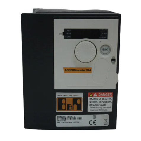
B&R ACOPOSinverter P84 User manual

ACOPOSinverter P84
User's manual
Version: 2.10 (October 2017)
Model no.: MAACPIP84-ENG
Translation of the original documentation
All values in this manual are current as of its creation. We reserve the right to change the contents of this manual
without notice. B&R Industrial Automation GmbH is not liable for technical or editorial errors and defects in this
manual. In addition, B&R Industrial Automation GmbH assumes no liability for damages that are directly or indirectly
attributable to the delivery, performance or use of this material. We point out that the software and hardware
designations and brand names of the respective companies used in this document are subject to general trademark,
brand or patent protection.


Table of contents
ACOPOSinverter P84 User's Manual 2.10 3
1 Installation guide.......................................................................................................6
1.1 Important information...................................................................................................................................... 6
1.2 Before you begin.............................................................................................................................................7
1.3 Low power.......................................................................................................................................................9
1.3.1 Steps for setting up................................................................................................................................. 10
1.3.2 Preliminary recommendations................................................................................................................. 11
1.3.3 Order data............................................................................................................................................... 13
1.3.4 Technical data......................................................................................................................................... 29
1.3.5 Max. leakage current...............................................................................................................................61
1.3.6 Mounting and temperature conditions.....................................................................................................62
1.3.7 Installation in a wall or free-standing enclosure......................................................................................65
1.3.8 Installation of the graphic display terminal..............................................................................................68
1.3.9 Position of the LED status indicator of the capacitor charge..................................................................69
1.3.10 Installing the option cards..................................................................................................................... 70
1.3.11 Installation of EMC plates......................................................................................................................72
1.3.12 Wiring recommendations.......................................................................................................................74
1.3.13 Power terminals.....................................................................................................................................77
1.3.14 Control terminals................................................................................................................................... 79
1.3.15 Option terminals.................................................................................................................................... 84
1.3.16 Connection diagram.............................................................................................................................. 85
1.3.17 Operation in IT system or distribution network with grounding of the type "corner-grounded".............. 90
1.3.18 Electromagnetic compatibility - wiring................................................................................................... 91
2 Programming guidelines........................................................................................ 93
2.1 Before you begin...........................................................................................................................................93
2.2 Steps for setting up...................................................................................................................................... 94
2.3 Factory configuration.....................................................................................................................................95
2.4 Application Functions....................................................................................................................................96
2.4.1 Motor control functions............................................................................................................................ 96
2.4.2 Functions of the speed references......................................................................................................... 96
2.4.3 Application-specific functions...................................................................................................................97
2.4.4 Functions of the speed references......................................................................................................... 97
2.5 Commissioning - Preliminary Recommendations.........................................................................................98
2.5.1 Switching on and the configuration of the inverter................................................................................. 98
2.5.2 Separate voltage supply of the control unit............................................................................................ 98
2.5.3 On/Off switching of the power supply via the line contactor...................................................................98
2.5.4 Adaptation and extension of functions by the user.................................................................................99
2.5.5 Starting the device...................................................................................................................................99
2.5.6 Firmware of the 8I0IF248.300-1..............................................................................................................99
2.5.7 Test on a low power motor or without a motor:.................................................................................... 100
2.5.8 The use of motors connected in parallel.............................................................................................. 100
2.5.9 Motor with a lower rated voltage than the power supply of the inverter............................................... 100
2.5.10 Operation with SDC.............................................................................................................................101
2.6 Graphic display terminal............................................................................................................................. 104
2.6.1 Description of the terminal.................................................................................................................... 104
2.6.2 Description of the screen...................................................................................................................... 105
2.6.3 Codes for the inverter state:................................................................................................................. 106
2.6.4 Example of configuration windows........................................................................................................107
2.6.5 Example configuration window for one value:...................................................................................... 107
2.6.6 Initial turn-on - [LANGUAGE] menu......................................................................................................108
2.6.7 Subsequent power ups..........................................................................................................................109
2.6.8 Programming: Example for setting a parameter................................................................................... 110
2.6.9 Quick navigation.................................................................................................................................... 111
2.6.10 [MAIN MENU]...................................................................................................................................... 112
2.6.11 [DRIVE MENU].................................................................................................................................... 113
2.7 Integrated display terminal..........................................................................................................................114
2.7.1 Functions of the display and keys........................................................................................................ 114

Table of contents
4 ACOPOSinverter P84 User's Manual 2.10
2.7.2 Accessing the menus............................................................................................................................ 115
2.7.3 Accessing the menu parameters...........................................................................................................116
2.7.4 Selection of multiple assignments for one parameter...........................................................................116
2.8 Programming............................................................................................................................................... 117
2.8.1 [ACCESS LEVEL](LAC-)....................................................................................................................... 117
2.8.2 Structure of parameter tables................................................................................................................120
2.8.3 Independence of the parameter values................................................................................................ 121
2.8.4 Finding a parameter in this document.................................................................................................. 122
2.8.5 [SIMPLE START](SIM-)......................................................................................................................... 123
2.8.6 [MONITOR] (SUP-)................................................................................................................................131
2.8.7 [SETTINGS] (SEt-)................................................................................................................................ 139
2.8.8 [MOTOR CONTROL] (drC-).................................................................................................................. 151
2.8.9 [INPUTS/ OUTPUTS] (I-O-).................................................................................................................. 166
2.8.10 [COMMAND] (CtL-)..............................................................................................................................184
2.8.11 [APPLICATION FUNCT.] (FUn-)..........................................................................................................196
2.8.12 [FAULT MANAGEMENT] (FLt-)........................................................................................................... 288
2.8.13 [COMMUNICATION] (COM-)...............................................................................................................308
2.8.14 [DIAGNOSTICS].................................................................................................................................. 311
2.8.15 [IDENTIFICATION].............................................................................................................................. 313
2.8.16 [FACTORY SETTINGS] (FCS-)...........................................................................................................314
2.8.17 [USER MENU] (USr)........................................................................................................................... 318
2.8.18 [LOAD / SAVE AS].............................................................................................................................. 319
2.8.19 [Access code] (COd-)..........................................................................................................................321
2.8.20 [SELECT DISPLAY TYPE]..................................................................................................................324
2.8.21 [DISPLAY CONFIG.]............................................................................................................................328
2.8.22 [CONNECT MULTI-POINT]................................................................................................................. 333
2.9 Servicing......................................................................................................................................................334
2.9.1 Service................................................................................................................................................... 334
2.9.2 Assistance during maintenance, fault display....................................................................................... 334
2.9.3 [DIAGNOSIS] menu...............................................................................................................................334
2.9.4 Clearing the fault................................................................................................................................... 334
2.9.5 Menu [MONITOR] (SUP-)..................................................................................................................... 334
2.9.6 Spares and repairs................................................................................................................................ 334
2.10 Fault - Causes - Measures.......................................................................................................................335
2.10.1 The inverter does not start and no error is displayed.........................................................................335
2.10.2 Faults that do not allow automatic switch on again............................................................................ 335
2.10.3 Faults that allow an automatic restart after eliminating the cause......................................................337
2.10.4 Fault that can be eliminated as soon as the cause is removed..........................................................339
2.10.5 Change or removal of the option card................................................................................................ 339
2.10.6 Changing the control card...................................................................................................................339
2.11 Tables with user-specific settings............................................................................................................. 340
2.11.1 Menu [SIMPLE START] (SIM-)............................................................................................................340
2.11.2 Functional assignment of the I/O........................................................................................................ 340
2.11.3 Other parameters (table to be created by the user)........................................................................... 341
3 Integrated safety functions.................................................................................. 342
3.1 Before you begin.........................................................................................................................................342
3.1.1 Safety instructions................................................................................................................................. 342
3.1.2 Personnel qualifications and usage...................................................................................................... 343
3.2 Overview......................................................................................................................................................345
3.2.1 Introduction............................................................................................................................................ 345
3.2.2 Standards and terminology................................................................................................................... 346
3.2.3 Basic information................................................................................................................................... 347
3.3 Description...................................................................................................................................................349
3.3.1 (PWR) Power removal (STO - Safe torque off).................................................................................... 349
3.4 Incompatibility with the safety functions..................................................................................................... 351
3.4.1 Limitations..............................................................................................................................................351

Table of contents
ACOPOSinverter P84 User's Manual 2.10 5
3.5 Safety monitoring........................................................................................................................................ 353
3.6 Technical data.............................................................................................................................................354
3.6.1 Electrical data........................................................................................................................................ 354
3.6.2 Capacity of the safety functions............................................................................................................354
4 Accessories........................................................................................................... 366
4.1 Overview......................................................................................................................................................366
4.2 Graphics display..........................................................................................................................................368
4.2.1 Order data............................................................................................................................................. 368
4.3 Mains choke................................................................................................................................................ 369
4.3.1 Order data............................................................................................................................................. 369
4.3.2 Technical data....................................................................................................................................... 369
4.3.3 Wiring.....................................................................................................................................................371
4.3.4 Dimensions............................................................................................................................................ 373
4.4 Braking resistors......................................................................................................................................... 374
4.4.1 Order data............................................................................................................................................. 374
4.4.2 Technical data....................................................................................................................................... 374
4.4.3 Dimensions and Installation recommendations.....................................................................................376
4.4.4 Characteristic curve for braking resistors..............................................................................................377
4.5 Additional EMC filters................................................................................................................................. 378
4.5.1 Order data............................................................................................................................................. 378
4.5.2 Technical data....................................................................................................................................... 378
4.5.3 Installation..............................................................................................................................................381
4.5.4 Wiring.....................................................................................................................................................385
4.5.5 Dimensions............................................................................................................................................ 385
4.6 Through-hole mounting kits........................................................................................................................ 387
4.6.1 Order data............................................................................................................................................. 387
4.6.2 Dimensions............................................................................................................................................ 389
4.7 Fans.............................................................................................................................................................390
4.7.1 Fans....................................................................................................................................................... 390
4.7.2 Installation..............................................................................................................................................391
4.8 Control card - fan kits.................................................................................................................................396
4.8.1 Order data............................................................................................................................................. 396
4.9 Incremental encoder interface.................................................................................................................... 397
4.9.1 Order data............................................................................................................................................. 397
4.9.2 Technical data....................................................................................................................................... 397
4.10 DC bus chokes......................................................................................................................................... 401
4.10.1 Order data........................................................................................................................................... 401
4.10.2 Dimensions.......................................................................................................................................... 401
4.10.3 Installation............................................................................................................................................403
4.10.4 Wiring...................................................................................................................................................404
5 Register description............................................................................................. 405

Installation guide
6 ACOPOSinverter P84 User's Manual 2.10
1 Installation guide
1.1 Important information
Note:
Read these instructions carefully and make yourself familiar with the device before you install, com-
mission or service it.
The aim of the warnings below in these instructions or indicated on the device is to protect you from
possible hazards or to refer you to information that explains or simplifies operations.
Danger!
DANGER indicates a directly hazardous situation, which if not avoided, could result in death, serious
bodily injury and/or material damage.
Warning!
WARNING indicates a potentially hazardous situation, which if not avoided, could result in death, se-
rious bodily injury and/or material damage.
Caution!
CAUTION indicates a potentially hazardous situation, which if not avoided, could result in bodily injury
and/or material damage.
Information:
Only qualified personnel are entitled to perform maintenance work on electrical devices. No responsi-
bility is assumed by B&R for any consequences arising out of the use of this device. This document
is not intended as a manual for untrained operators.

Installation guide
ACOPOSinverter P84 User's Manual 2.10 7
1.2 Before you begin
Read and understand these instructions before performing any procedure on this frequency inverter.
Danger!
HAZARD OF ELECTRICAL SHOCK, EXPLOSION OR ARC FLASH
•Read and understand this manual before installing and operating the ACOPOSinverter P84.
Installation, adjustment, repair and maintenance must be performed by qualified personnel.
•The user is responsible for complying with all relevant international and national electrical en-
gineering requirements regarding the protective grounding of all equipment.
•Numerous components of the frequency inverter, including the circuit boards, are supplied via
the mains voltage. DO NOT TOUCH! Use only electrically insulated tools.
•DO NOT TOUCH shielded components or bolted connections on terminal blocks while connect-
ed to the power supply.
•DO NOT short across terminals PA/+ and PC/– or the DC bus capacitors.
•Before servicing the frequency inverter:
– Disconnect any power supply.
– Place a "DO NOT TURN ON" label on the power or disconnection switch.
– Lock the power or disconnection switch in the open position.
– WAIT 15 MINUTES to allow the DC bus capacitors to discharge. Then perform the pro-
cedure for measuring the DC bus voltage, see "Position of the LED status indicator of
the capacitor charge" on page 69, to check whether the DC voltage is below 42 V. The
LEDs on the inverter can no longer display whether there is no DC bus voltage.
– If the DC bus capacitors do not discharge completely, contact your local B&R represen-
tative. The frequency inverter is not permitted to be repaired or put into operation in
this case.
•Install all covers and close them before turning the power on or before the starting and stopping
the frequency inverter.
Failure to follow these instructions can result in death or injury.
Danger!
ACCIDENTAL OPERATION OF DEVICE
•Read and understand this manual before installing and operating the ACOPOSinverter P84.
•Any changes made to the parameter settings must be performed by qualified personnel.
Failure to follow these instructions can result in death or injury.
Warning!
EQUIPMENT DAMAGE
Do not operate or install any frequency inverter or accessory that appears damaged.
Failure to follow these instructions can result in death, serious injury or material damages.

Installation guide
8 ACOPOSinverter P84 User's Manual 2.10
Warning!
CONTROL FAILURE
•The designer of any wiring scheme must consider the potential failure modes of control chan-
nels and, for certain critical functions, provide a means to achieve a safe state during and after
a channel failure. Examples of critical control functions: Emergency stop and stopping in the
case of an overrun traverse that is too long.
•Separate or redundant control channels must be provided for critical control functions.
•System control channels may include communication links. The effects of unexpected trans-
mission delays or failures must be taken into account. 1)
Failure to follow these instructions can result in death, serious injury or material damages.
1) For additional information, refer to NEMA ICS 1.1 (latest edition), "Safety guidelines for the application, installa-
tion and maintenance of solid state control" and to NEMA ICS 7.1 (latest edition), "Safety standards for construction
and guide for selection, installation and operation of adjustable-speed drive systems."
Caution!
INCOMPATIBLE MAINS VOLTAGE
Before switching on and configuring the frequency inverter, ensure that the mains voltage is compat-
ible with the supply voltage shown on the frequency inverter nameplate. The frequency inverter may
be damaged if the mains voltage is not compatible.
Failure to follow these instructions can result in injury or equipment damage.
Caution!
IMPROPER OPERATION OF THE INVERTER
•If the inverter has not been turned on over a longer period of time, the performance of the
electrolytic capacitors is reduced.
•If the inverter remains out of operation for a longer period, switch it on every 2 years for at
least 5 hours to reestablish the performance of the capacitors. Then check the operation of the
inverter. It is recommended not to connect the inverter directly to the mains voltage, but rather
to increase the voltage gradually with the aid of an adjustable AC voltage source.
Failure to follow these instructions can result in injury and/or equipment damage.
1) For additional information, refer to NEMA ICS 1.1 (latest edition), "Safety Guidelines for the Application, Installation and Maintenance of Solid State Control"
and to NEMA ICS 7.1 (latest edition), "Safety Standards for Construction and Guide for Selection, Installation and Operation of Adjustable-Speed Drive Sys-
tems."

Installation guide
ACOPOSinverter P84 User's Manual 2.10 9
1.3 Low power
L POW OWER
0.37 kW to 45 kW / 200 to 240 V
0.75 kW to 75 kW / 380 to 480 V

Installation guide
10 ACOPOSinverter P84 User's Manual 2.10
1.3.1 Steps for setting up
INSTALLATION
1. Receipt and testing of the inverter control
– Check that the catalog number printed on the nameplate is the same as that on your
purchase order.
– Remove the ACOPOSinverter from its packaging and check that it has not been damaged
in transit.
Steps 1 to 4 must be
carried out in a
voltage-free
state.
2. Line voltage compatibility check
– Check that the supply voltage is compatible with the voltage range of the
inverter (see "Technical data" on page 29).
3. Installing the frequency inverter
– Install the inverter in accordance with the instructions in this
document.
– If required, install the internal and external options.
4. Wiring the frequency inverter
– Connect the motor and make sure that the motor connec-
tion corresponds to the mains voltage.
– After making sure that the power is off, connect the line
supply.
– Connect the control part.
– Connect the frequency reference line.

Installation guide
ACOPOSinverter P84 User's Manual 2.10 11
1.3.2 Preliminary recommendations
1.3.2.1 Handling and storage
To ensure the protection of the frequency inverter before assembly, the device should be moved and stored in its
packaged condition. Ensure that the ambient conditions are permissible.
Warning!
PACKAGING DAMAGE
If the packaging is damaged, opening it or any further handling could be hazardous.
In this case, take the appropriate precautions.
Failure to follow these instructions can result in death, serious injury or material damages.
Warning!
DAMAGED EQUIPMENT
Do not operate or install the inverter, if it is damaged.
Failure to follow this instruction can result in death, serious injury or material damages.
1.3.2.2 Handling during installation
Up to the models 8I84T201500.01P-1 and 8I84T401850.01P-1, the ACOPOSinverter
P84 can be unpacked and installed without a transport fixture.
45° max.
The use of a hoist is required for larger inverter models. To this end, all these inverters
are equipped with lifting eyes. Refer to the recommendations on the next page.

Installation guide
12 ACOPOSinverter P84 User's Manual 2.10
1.3.2.3 Before you begin
Read the instructions in the "Programming guide" carefully.
Caution!
INCOMPATIBLE MAINS VOLTAGE
Before switching on and configuring the frequency inverter, ensure that the mains voltage is compat-
ible with the supply voltage shown on the frequency inverter nameplate. The frequency inverter may
be damaged if the mains voltage is not compatible.
Failure to follow these instructions can result in injury and/or equipment damage.
Danger!
ACCIDENTAL OPERATION OF DEVICE
•Before turning on and configuring the ACOPOSinverter P84, to avoid an unintended operation
ensure that the PWR input (POWER REMOVAL) is deactivated (state 0).
•Before you turn on the inverter or when you exit the configuration menu make sure that the
inputs assigned to the operating commands are deactivated (state 0), since these could result
in the immediate starting of the motor.
Failure to follow these instructions can result in death or injury.
Information:
If unwanted or unintended operation must be excluded for the safety of the operating personnel, the
function "Power Removal" electronically locks the ACOPOSinverter P84.
This function requires the use of a connection diagram that corresponds to the standards IEC/EN 61508
Safety Integrity Level SIL 2 and ISO 13849 PL d.
The power-removal function (PWR) has priority before every operating command.
Note:
The ACOPOSinverter P84 is supported starting with AS V3.0.80.25.

Installation guide
ACOPOSinverter P84 User's Manual 2.10 13
1.3.3 Order data
1.3.3.1 8I84T200037.01P-1, 8I84T200075.01P-1, 8I84T200150.01P-1
Model number Short description Figure
ACOPOSinverter P84 3-phase 200-240V
8I84T200037.01P-1 ACOPOSinverter P84, 3x 200 to 240 V, 0.37 kW, integrated EMC
filter and brake chopper, shield plate included in delivery, POW-
ERLINK interface
8I84T200075.01P-1 ACOPOSinverter P84, 3x 200 to 240 V, 0.75 kW and 1x 200 to
240 V, 0.37 kW, integrated EMC filter and brake chopper, shield
plate included in delivery, POWERLINK interface
8I84T200150.01P-1 ACOPOSinverter P84, 3x 200 to 240 V, 1.5 kW and 1x 200 to
240 V, 0.75 kW, integrated EMC filter and brake chopper, shield
plate included in delivery, POWERLINK interface
Optional accessories
ACOPOSinverter P74/P76/P84 - Line chokes
8I0CT004.000-1 Mains choke 3-phase 4 A, for ACOPOSinverter P74 3x 380 to
500 V, 0.37 to 1.5 kW, for ACOPOSinverter P84 3x 200 to 240
V, 0.37 to 0.75 kW and 3x 380 to 480 V, 0.75 to 1.5 kW
8I0CT010.000-1 Mains choke 3-phase 10 A, for ACOPOSinverter P74 3x 380 to
500 V, 2.2 to 4 kW, for ACOPOSinverter P84 3x 200 to 240 V,
1.5 to 2.2 kW and 3x 380 to 480 V, 2.2 to 4 kW
ACOPOSinverter P74/P84 - Braking resistors
8I0BR060.000-1 Braking resistor 60 Ω, continuous braking power 0.1 kW, for
ACOPOSinverter P74 1x200 to 240 V, 2.2 kW and 3x 380 to 500
V, 5.5 to 7.5 kW, for ACOPOSinverter P84 3x 200 to 240 V, 1.5
to 2.2 kW and 3x 380 to 480 V, 5.5 to 7.5 kW
8I0BR100.000-1 Braking resistor 100 Ω, continuous braking power 0.05 kW, for
ACOPOSinverter P74 1x200 to 240 V, 0.18 to 1.5 kW and 3x
380 to 500 V, 0.37 to 4 kW for ACOPOSinverter P84 3x 200 to
240 V, 0.37 to 0.75 kW and 3x 380 to 480 V, 0.75 to 4 kW
ACOPOSinverter P74/P84 - Graphics display
8I0XD301.300-1 ACOPOSinverter P74/P84 graphics display, 8 lines, 240 x 160
pixels, backlight, function keys, navigation keys, IP54 protection
8I0XD302.300-1 Remote installation kit for graphics display, IP54 protection
8I0XD303.300-1 Front cover for the remote installation kit for graphics display,
IP65 protection
8I0XD304.301-1 Graphics display remote cable 1 m for ACOPOSinverter P74/
P84 (RJ45 - RJ45)
8I0XD304.303-1 Graphics display remote cable 3 m for ACOPOSinverter P74/
P84 (RJ45 - RJ45)
8I0XD304.305-1 Graphics display remote cable 5 m for ACOPOSinverter P74/
P84 (RJ45 - RJ45)
8I0XD304.310-1 Graphics display remote cable 10 m for ACOPOSinverter P74/
P84 (RJ45 - RJ45)
8I0XD305.300-1 RJ45 adapter for graphic display
ACOPOSinverter P74/P84 - Mains chokes
8I0CS045.000-1 Mains choke 1-phase 45 A, for ACOPOSinverter P84 1x 200 to
240 V, 4 to 5.5 kW
ACOPOSinverter P84 - Additional EMC input filters
8I0FT012.300-1 EMC filter 3-phase 12 A, bottom or side installation, for
ACOPOSinverter P84 3x 200 to 240 V, 0.37 to 1.5 kW and 3x
380 to 480 V, 0.75 to 2.2 kW
ACOPOSinverter P84 - DC bus choke
8I0DC002.300-1 DC bus choke 2 A, for ACOPOSinverter P84 3x 200 to 240 V,
0.37 kW and 3x 380 to 480 V, 0.75 kW
8I0DC008.300-1 DC bus choke 8 A, for ACOPOSinverter P84 3x 200 to 240 V,
0.75 kW and 3x 380 to 480 V, 2.2 to 3 kW
8I0DC014.300-1 DC bus choke 14 A, for ACOPOSinverter P84 3x 200 to 240 V,
1.5 kW and 3x 380 to 480 V, 5.5 kW
ACOPOSinverter P84 - Fan
8I0XF084.020-1 Fan for ACOPOSinverter 3x 200 to 240 V, 0.37 to 1.5 kW and
3x 380 to 480 V, 0.75 to 2.2 kW
ACOPOSinverter P84 - Feed-through mounting kits
8I0MF001.300-1 Feed-through mounting kit, for ACOPOSinverter P84 3x 200 to
240 V, 0.37 to 1.5 kW and 3x 380 to 480 V, 0.75 to 2.2 kW
ACOPOSinverter P84 - Incremental encoder interfaces
8I0AC123.300-1 ACOPOSinverter P84 plug-in module, incremental encoder in-
terface for RS422 signals (TTL), 5 V supply voltage
8I0AC123.301-1 ACOPOSinverter P84 plug-in module, incremental encoder in-
terface for RS422 signals (TTL), 15 V supply voltage
8I0AC123.302-1 ACOPOSinverter P84 plug-in module, incremental encoder in-
terface for open collector, 12 V supply voltage
Table 1: 8I84T200037.01P-1, 8I84T200075.01P-1, 8I84T200150.01P-1 - Order data

Installation guide
14 ACOPOSinverter P84 User's Manual 2.10
Model number Short description Figure
8I0AC123.303-1 ACOPOSinverter P84 plug-in module, incremental encoder in-
terface for open collector, 15 V supply voltage
8I0AC123.304-1 ACOPOSinverter P84 plug-in module, incremental encoder in-
terface for push-pull HTL, 12 V supply voltage
8I0AC123.305-1 ACOPOSinverter P84 plug-in module, incremental encoder in-
terface for push-pull HTL, 15 V supply voltage
8I0AC123.306-1 ACOPOSinverter P84 plug-in module, incremental encoder in-
terface for push-pull HTL, 24 V supply voltage
Table 1: 8I84T200037.01P-1, 8I84T200075.01P-1, 8I84T200150.01P-1 - Order data

Installation guide
ACOPOSinverter P84 User's Manual 2.10 15
1.3.3.2 8I84T200220.01P-1, 8I84T200300.01P-1, 8I84T200400.01P-1
Model number Short description Figure
ACOPOSinverter P84 3-phase 200-240V
8I84T200220.01P-1 ACOPOSinverter P84, 3x 200 to 240 V, 2.2 kW and 1x 200 to
240 V, 1.5 kW, integrated EMC filter and brake chopper, shield
plate included in delivery, POWERLINK interface
8I84T200300.01P-1 ACOPOSinverter P84, 3x 200 to 240 V, 3 kW and 1x 200 to 240
V, 2.2 kW, integrated EMC filter and brake chopper, shield plate
included in delivery, POWERLINK interface
8I84T200400.01P-1 ACOPOSinverter P84, 3x 200 to 240 V, 4 kW and 1x 200 to 240
V, 3 kW, integrated EMC filter and brake chopper, shield plate
included in delivery, POWERLINK interface
Optional accessories
ACOPOSinverter P74/P76/P84 - Line chokes
8I0CT010.000-1 Mains choke 3-phase 10 A, for ACOPOSinverter P74 3x 380 to
500 V, 2.2 to 4 kW, for ACOPOSinverter P84 3x 200 to 240 V,
1.5 to 2.2 kW and 3x 380 to 480 V, 2.2 to 4 kW
8I0CT016.000-1 Mains choke, 3-phase 17 A, for ACOPOSinverter P74 3x 380 to
500 V, 5.5 to 7.5 kW, for ACOPOSinverter P84 3x 200 to 240 V,
3 kW and 3x 380 to 480 V, 5.5 to 7.5 kW
8I0CT030.000-1 Mains choke 3-phase 30 A, for ACOPOSinverter P74 3x 380 to
500 V, 11 to 15 kW, for ACOPOSinverter P84 3x 200 to 240 V,
4 to 5.5 kW and 3x 380 to 480 V, 11 to 15 kW
ACOPOSinverter P74/P84 - Braking resistors
8I0BR028.000-1 Braking resistor 28 Ω continuous braking power 0.2 kW, for
ACOPOSinverter P74 3x 380 to 500 V, 11 to 15 kW, for
ACOPOSinverter P84 3x 200 to 240 V, 3 to 4 kW and 3x 380
to 480 V, 11 to 15 kW
8I0BR060.000-1 Braking resistor 60 Ω, continuous braking power 0.1 kW, for
ACOPOSinverter P74 1x200 to 240 V, 2.2 kW and 3x 380 to 500
V, 5.5 to 7.5 kW, for ACOPOSinverter P84 3x 200 to 240 V, 1.5
to 2.2 kW and 3x 380 to 480 V, 5.5 to 7.5 kW
ACOPOSinverter P74/P84 - Graphics display
8I0XD301.300-1 ACOPOSinverter P74/P84 graphics display, 8 lines, 240 x 160
pixels, backlight, function keys, navigation keys, IP54 protection
8I0XD302.300-1 Remote installation kit for graphics display, IP54 protection
8I0XD303.300-1 Front cover for the remote installation kit for graphics display,
IP65 protection
8I0XD304.301-1 Graphics display remote cable 1 m for ACOPOSinverter P74/
P84 (RJ45 - RJ45)
8I0XD304.303-1 Graphics display remote cable 3 m for ACOPOSinverter P74/
P84 (RJ45 - RJ45)
8I0XD304.305-1 Graphics display remote cable 5 m for ACOPOSinverter P74/
P84 (RJ45 - RJ45)
8I0XD304.310-1 Graphics display remote cable 10 m for ACOPOSinverter P74/
P84 (RJ45 - RJ45)
8I0XD305.300-1 RJ45 adapter for graphic display
ACOPOSinverter P74/P84 - Mains chokes
8I0CS025.000-1 Mains choke 1-phase 25 A, for ACOPOSinverter P84 1x 200 to
240 V, 3 kW
ACOPOSinverter P84 - Additional EMC input filters
8I0FT026.300-1 EMC filter 3-phase 26 A, bottom or side installation, for
ACOPOSinverter P84 3x 200 to 240 V, 2.2 to 4 kW and 3x 380
to 480 V, 3 to 4 kW
ACOPOSinverter P84 - DC bus choke
8I0DC019.300-1 DC bus choke 19 A, for ACOPOSinverter P84 3x 200 to 240 V,
2.2 kW and 3x 380 to 480 V, 7.5 kW
8I0DC027.300-1 DC bus choke 27 A, for ACOPOSinverter P84 3x 200 to 240 V,
3 kW and 3x 380 to 480 V, 11 kW
8I0DC044.300-1 DC bus choke 44 A, for ACOPOSinverter P84 3x 200 to 240 V,
4 to 5 kW and 3x 380 to 480 V, 15 to 18.5 kW
ACOPOSinverter P84 - Fan
8I0XF084.030-1 Fan for ACOPOSinverter P84 3x 200 to 240 V, 2.2 to 4 kW and
3x 380 to 480 V, 3 to 4 kW
ACOPOSinverter P84 - Feed-through mounting kits
8I0MF002.300-1 Feed-through mounting kit, for ACOPOSinverter P84 3x 200 to
240 V, 2.2 to 4 kW and 3x 380 to 480 V, 3 to 4 kW
ACOPOSinverter P84 - Incremental encoder interfaces
8I0AC123.300-1 ACOPOSinverter P84 plug-in module, incremental encoder in-
terface for RS422 signals (TTL), 5 V supply voltage
8I0AC123.301-1 ACOPOSinverter P84 plug-in module, incremental encoder in-
terface for RS422 signals (TTL), 15 V supply voltage
8I0AC123.302-1 ACOPOSinverter P84 plug-in module, incremental encoder in-
terface for open collector, 12 V supply voltage
Table 2: 8I84T200220.01P-1, 8I84T200300.01P-1, 8I84T200400.01P-1 - Order data

Installation guide
16 ACOPOSinverter P84 User's Manual 2.10
Model number Short description Figure
8I0AC123.303-1 ACOPOSinverter P84 plug-in module, incremental encoder in-
terface for open collector, 15 V supply voltage
8I0AC123.304-1 ACOPOSinverter P84 plug-in module, incremental encoder in-
terface for push-pull HTL, 12 V supply voltage
8I0AC123.305-1 ACOPOSinverter P84 plug-in module, incremental encoder in-
terface for push-pull HTL, 15 V supply voltage
8I0AC123.306-1 ACOPOSinverter P84 plug-in module, incremental encoder in-
terface for push-pull HTL, 24 V supply voltage
Table 2: 8I84T200220.01P-1, 8I84T200300.01P-1, 8I84T200400.01P-1 - Order data

Installation guide
ACOPOSinverter P84 User's Manual 2.10 17
1.3.3.3 8I84T200550.01P-1, 8I84T200750.01P-1, 8I84T201100.01P-1
Model number Short description Figure
ACOPOSinverter P84 3-phase 200-240V
8I84T200550.01P-1 ACOPOSinverter P84, 3x 200 to 240 V, 5.5 kW and 1x 200 to
240 V, 4 kW, integrated EMC filter and brake chopper, shield
plate included in delivery, POWERLINK interface
8I84T200750.01P-1 ACOPOSinverter P84, 3x 200 to 240 V, 7.5 kW and 1x 200 to
240 V, 5.5 kW, integrated EMC filter and brake chopper, shield
plate included in delivery, POWERLINK interface
8I84T201100.01P-1 ACOPOSinverter P84, 3x 200 to 240 V, 11 kW, integrated brake
chopper, shield plate included in delivery, POWERLINK inter-
face
Optional accessories
ACOPOSinverter P74/P76/P84 - Line chokes
8I0CT030.000-1 Mains choke 3-phase 30 A, for ACOPOSinverter P74 3x 380 to
500 V, 11 to 15 kW, for ACOPOSinverter P84 3x 200 to 240 V,
4 to 5.5 kW and 3x 380 to 480 V, 11 to 15 kW
ACOPOSinverter P74/P84 - Braking resistors
8I0BR010.000-1 Braking resistor 10 ohms, continuous braking power 1 kW, for
ACOPOSinverter P84 3x 200 to 240 V, 11 kW and 3x 380 to 480
V, 37 kW
8I0BR015.000-1 Braking resistor 15 ohms, continuous braking power 1 kW, for
ACOPOSinverter P84 3x 200 to 240 V, 5.5 to 7.5 kW and 3x 380
to 480 V, 18.5 to 30 kW
ACOPOSinverter P74/P84 - Graphics display
8I0XD301.300-1 ACOPOSinverter P74/P84 graphics display, 8 lines, 240 x 160
pixels, backlight, function keys, navigation keys, IP54 protection
8I0XD302.300-1 Remote installation kit for graphics display, IP54 protection
8I0XD303.300-1 Front cover for the remote installation kit for graphics display,
IP65 protection
8I0XD304.301-1 Graphics display remote cable 1 m for ACOPOSinverter P74/
P84 (RJ45 - RJ45)
8I0XD304.303-1 Graphics display remote cable 3 m for ACOPOSinverter P74/
P84 (RJ45 - RJ45)
8I0XD304.305-1 Graphics display remote cable 5 m for ACOPOSinverter P74/
P84 (RJ45 - RJ45)
8I0XD304.310-1 Graphics display remote cable 10 m for ACOPOSinverter P74/
P84 (RJ45 - RJ45)
8I0XD305.300-1 RJ45 adapter for graphic display
ACOPOSinverter P74/P84 - Mains chokes
8I0CT060.000-1 Mains choke 3-phase 60 A, for ACOPOSinverter P84 3x 200 to
240 V, 7.5 to 11 kW and 3x 380 to 480 V, 18.5 to 22 kW
ACOPOSinverter P84 - Additional EMC input filters
8I0FT035.300-1 EMC filter 3-phase 35 A, bottom or side installation, for
ACOPOSinverter P84 3x 200 to 240 V, 5.5 kW and 3x 380 to
480 V, 5.5 to 7.5 kW
8I0FT046.300-1 EMC filter 3-phase 46 A, bottom or side installation, for
ACOPOSinverter P84 3x 200 to 240 V, 7.5 kW and 3x 380 to
480 V, 11 kW
8I0FT072.300-1 EMC filter 3-phase 72 A, bottom or side installation, for
ACOPOSinverter P84 3x 200 to 240 V, 11 to 15 kW and 3x 380
to 480 V, 15 to 18.5 kW
ACOPOSinverter P84 - DC bus choke
8I0DC036.300-1 DC bus choke 36 A, for ACOPOSinverter P84 3x 200 to 240 V,
7.5 kW
8I0DC044.300-1 DC bus choke 44 A, for ACOPOSinverter P84 3x 200 to 240 V,
4 to 5 kW and 3x 380 to 480 V, 15 to 18.5 kW
8I0DC084.300-1 DC bus choke 84 A, for ACOPOSinverter P84 3x 200 to 240 V,
11 to 15 kW and 3x 380 to 480 V, 22 to 37 kW
ACOPOSinverter P84 - Fan
8I0XF084.040-1 Fan for ACOPOSinverter P84 3x 200 to 240 V, 5.5 kW and 3x
380 to 480 V, 5.5 to 7.5 kW
8I0XF084.050-1 Fan for ACOPOSinverter P84 3x 200 to 240 V, 7.5 kW and 3x
380 to 480 V, 11 kW
8I0XF084.055-1 Fan for ACOPOSinverter P84 3x 200 to 240 V, 11 to 15 kW and
3x 380 to 480 V, 15 to 18.5 kW
ACOPOSinverter P84 - Feed-through mounting kits
8I0MF003.300-1 Feed-through mounting kit, for ACOPOSinverter P84 3x 200 to
240 V, 5.5 kW and 3x 380 to 480 V, 5.5 to 7.5 kW
8I0MF004.300-1 Feed-through mounting kit, for ACOPOSinverter P84 3x 200 to
240 V, 7.5 kW and 3x 380 to 480 V, 11 kW
8I0MF005.300-1 Feed-through mounting kit, for ACOPOSinverter P84 3x 200 to
240 V, 11 to 15 kW and 3x 380 to 480 V, 15 to 18.5 kW
ACOPOSinverter P84 - Incremental encoder interfaces
8I0AC123.300-1 ACOPOSinverter P84 plug-in module, incremental encoder in-
terface for RS422 signals (TTL), 5 V supply voltage
8I0AC123.301-1 ACOPOSinverter P84 plug-in module, incremental encoder in-
terface for RS422 signals (TTL), 15 V supply voltage
Table 3: 8I84T200550.01P-1, 8I84T200750.01P-1, 8I84T201100.01P-1 - Order data

Installation guide
18 ACOPOSinverter P84 User's Manual 2.10
Model number Short description Figure
8I0AC123.302-1 ACOPOSinverter P84 plug-in module, incremental encoder in-
terface for open collector, 12 V supply voltage
8I0AC123.303-1 ACOPOSinverter P84 plug-in module, incremental encoder in-
terface for open collector, 15 V supply voltage
8I0AC123.304-1 ACOPOSinverter P84 plug-in module, incremental encoder in-
terface for push-pull HTL, 12 V supply voltage
8I0AC123.305-1 ACOPOSinverter P84 plug-in module, incremental encoder in-
terface for push-pull HTL, 15 V supply voltage
8I0AC123.306-1 ACOPOSinverter P84 plug-in module, incremental encoder in-
terface for push-pull HTL, 24 V supply voltage
Table 3: 8I84T200550.01P-1, 8I84T200750.01P-1, 8I84T201100.01P-1 - Order data

Installation guide
ACOPOSinverter P84 User's Manual 2.10 19
1.3.3.4 8I84T201500.01P-1, 8I84T201850.01P-1, 8I84T202200.01P-1
Model number Short description Figure
ACOPOSinverter P84 3-phase 200-240V
8I84T201500.01P-1 ACOPOSinverter P84, 3x 200 to 240 V, 15 kW, integrated brake
chopper, shield plate included in delivery, POWERLINK inter-
face
8I84T201850.01P-1 ACOPOSinverter P84, 3x 200 to 240 V, 18.5 kW, integrated
brake chopper, shield plate included in delivery, POWERLINK
interface
8I84T202200.01P-1 ACOPOSinverter P84, 3x 200 to 240 V, 22 kW, integrated brake
chopper, shield plate included in delivery, POWERLINK inter-
face
Optional accessories
ACOPOSinverter P74/P84 - Braking resistors
8I0BR005.000-1 Braking resistor 5 ohms, continuous braking power 1.3 kW, for
ACOPOSinverter P84 3x 200 to 240 V, 18.5 to 22 kW and 3x
380 to 480 V, 45 to 75 kW
8I0BR008.000-1 Braking resistor 8 ohms, continuous braking power 1 kW, for
ACOPOSinverter P84 3x 200 to 240 V, 15 kW
ACOPOSinverter P74/P84 - Graphics display
8I0XD301.300-1 ACOPOSinverter P74/P84 graphics display, 8 lines, 240 x 160
pixels, backlight, function keys, navigation keys, IP54 protection
8I0XD302.300-1 Remote installation kit for graphics display, IP54 protection
8I0XD303.300-1 Front cover for the remote installation kit for graphics display,
IP65 protection
8I0XD304.301-1 Graphics display remote cable 1 m for ACOPOSinverter P74/
P84 (RJ45 - RJ45)
8I0XD304.303-1 Graphics display remote cable 3 m for ACOPOSinverter P74/
P84 (RJ45 - RJ45)
8I0XD304.305-1 Graphics display remote cable 5 m for ACOPOSinverter P74/
P84 (RJ45 - RJ45)
8I0XD304.310-1 Graphics display remote cable 10 m for ACOPOSinverter P74/
P84 (RJ45 - RJ45)
8I0XD305.300-1 RJ45 adapter for graphic display
ACOPOSinverter P74/P84 - Mains chokes
8I0CT100.000-1 Mains choke 3-phase 100 A, for ACOPOSinverter P84 3x 200
to 240 V, 15 kW and 3x 380 to 480 V, 30 to 55 kW
ACOPOSinverter P84 - Additional EMC input filters
8I0FT072.300-1 EMC filter 3-phase 72 A, bottom or side installation, for
ACOPOSinverter P84 3x 200 to 240 V, 11 to 15 kW and 3x 380
to 480 V, 15 to 18.5 kW
8I0FT090.300-1 EMC filter 3-phase 90 A, bottom or side installation, for
ACOPOSinverter P84 3x 200 to 240 V, 18.5 to 22 kW and 3x
380 to 480 V, 22 kW
ACOPOSinverter P84 - Control card fan kits
8I0XF004.300-1 Control card fan kit, for ACOPOSinverter P84 3x 200 to 240 V,
18.5 to 22 kW and 3x 380 to 480 V, 22 kW, for operation at am-
bient temperature of 50 to 60°C
ACOPOSinverter P84 - DC bus choke
8I0DC084.300-1 DC bus choke 84 A, for ACOPOSinverter P84 3x 200 to 240 V,
11 to 15 kW and 3x 380 to 480 V, 22 to 37 kW
8I0DC171.300-1 DC bus choke 171 A, for ACOPOSinverter P84 3x 200 to 240 V,
18.5 to 22 kW and 3x 380 to 480 V, 45 to 75 kW
ACOPOSinverter P84 - Fan
8I0XF084.055-1 Fan for ACOPOSinverter P84 3x 200 to 240 V, 11 to 15 kW and
3x 380 to 480 V, 15 to 18.5 kW
8I0XF084.060-1 Fan for ACOPOSinverter P84 3x 200 to 240 V, 18.5 to 22 kW
and 3x 380 to 480 V, 22 kW
ACOPOSinverter P84 - Feed-through mounting kits
8I0MF005.300-1 Feed-through mounting kit, for ACOPOSinverter P84 3x 200 to
240 V, 11 to 15 kW and 3x 380 to 480 V, 15 to 18.5 kW
8I0MF006.300-1 Feed-through mounting kit, for ACOPOSinverter P84 3x 200 to
240 V, 18.5 to 22 kW and 3x 380 to 480 V, 22 kW
ACOPOSinverter P84 - Incremental encoder interfaces
8I0AC123.300-1 ACOPOSinverter P84 plug-in module, incremental encoder in-
terface for RS422 signals (TTL), 5 V supply voltage
8I0AC123.301-1 ACOPOSinverter P84 plug-in module, incremental encoder in-
terface for RS422 signals (TTL), 15 V supply voltage
8I0AC123.302-1 ACOPOSinverter P84 plug-in module, incremental encoder in-
terface for open collector, 12 V supply voltage
8I0AC123.303-1 ACOPOSinverter P84 plug-in module, incremental encoder in-
terface for open collector, 15 V supply voltage
8I0AC123.304-1 ACOPOSinverter P84 plug-in module, incremental encoder in-
terface for push-pull HTL, 12 V supply voltage
8I0AC123.305-1 ACOPOSinverter P84 plug-in module, incremental encoder in-
terface for push-pull HTL, 15 V supply voltage
8I0AC123.306-1 ACOPOSinverter P84 plug-in module, incremental encoder in-
terface for push-pull HTL, 24 V supply voltage
Table 4: 8I84T201500.01P-1, 8I84T201850.01P-1, 8I84T202200.01P-1 - Order data

Installation guide
20 ACOPOSinverter P84 User's Manual 2.10
1.3.3.5 8I84T203000.01P-1, 8I84T203700.01P-1, 8I84T204500.01P-1
Model number Short description Figure
ACOPOSinverter P84 3-phase 200-240V
8I84T203000.01P-1 ACOPOSinverter P84, 3x 200 to 240 V, 30 kW, integrated brake
chopper, shield plate included in delivery, POWERLINK inter-
face
8I84T203700.01P-1 ACOPOSinverter P84, 3x 200 to 240 V, 37 kW, integrated brake
chopper, shield plate included in delivery, POWERLINK inter-
face
8I84T204500.01P-1 ACOPOSinverter P84, 3x 200 to 240 V, 45 kW, integrated brake
chopper, shield plate included in delivery, POWERLINK inter-
face
Optional accessories
ACOPOSinverter P74/P84 - Graphics display
8I0XD301.300-1 ACOPOSinverter P74/P84 graphics display, 8 lines, 240 x 160
pixels, backlight, function keys, navigation keys, IP54 protection
8I0XD302.300-1 Remote installation kit for graphics display, IP54 protection
8I0XD303.300-1 Front cover for the remote installation kit for graphics display,
IP65 protection
8I0XD304.301-1 Graphics display remote cable 1 m for ACOPOSinverter P74/
P84 (RJ45 - RJ45)
8I0XD304.303-1 Graphics display remote cable 3 m for ACOPOSinverter P74/
P84 (RJ45 - RJ45)
8I0XD304.305-1 Graphics display remote cable 5 m for ACOPOSinverter P74/
P84 (RJ45 - RJ45)
8I0XD304.310-1 Graphics display remote cable 10 m for ACOPOSinverter P74/
P84 (RJ45 - RJ45)
8I0XD305.300-1 RJ45 adapter for graphic display
ACOPOSinverter P84 - Additional EMC input filters
8I0FT180.300-1 EMC filter 3-phase 180 A, bottom or side installation, for
ACOPOSinverter P84 3x 200 to 240 V, 30 to 45 kW and 3x 380
to 480 V, 45 to 75 kW
ACOPOSinverter P84 - Control card fan kits
8I0XF006.300-1 Control card fan kit, for ACOPOSinverter P84 3x 200 to 240 V,
30 to 45 kW, for operation at ambient temperature of 50 to 60°C
ACOPOSinverter P84 - DC bus choke
8I0DC195.300-1 DC bus choke 195 A, for ACOPOSinverter P84 3x 200 to 240
V, 30 to 45 kW
ACOPOSinverter P84 - Fan
8I0XF084.075-1 Fan for ACOPOSinverter P84 3x 200 to 240 V, 30 to 45 kW
ACOPOSinverter P84 - Feed-through mounting kits
8I0MF008.300-1 Feed-through mounting kit, for ACOPOSinverter P84 3x 200 to
240 V, 30 to 45 kW
ACOPOSinverter P84 - Incremental encoder interfaces
8I0AC123.300-1 ACOPOSinverter P84 plug-in module, incremental encoder in-
terface for RS422 signals (TTL), 5 V supply voltage
8I0AC123.301-1 ACOPOSinverter P84 plug-in module, incremental encoder in-
terface for RS422 signals (TTL), 15 V supply voltage
8I0AC123.302-1 ACOPOSinverter P84 plug-in module, incremental encoder in-
terface for open collector, 12 V supply voltage
8I0AC123.303-1 ACOPOSinverter P84 plug-in module, incremental encoder in-
terface for open collector, 15 V supply voltage
8I0AC123.304-1 ACOPOSinverter P84 plug-in module, incremental encoder in-
terface for push-pull HTL, 12 V supply voltage
8I0AC123.305-1 ACOPOSinverter P84 plug-in module, incremental encoder in-
terface for push-pull HTL, 15 V supply voltage
8I0AC123.306-1 ACOPOSinverter P84 plug-in module, incremental encoder in-
terface for push-pull HTL, 24 V supply voltage
Table 5: 8I84T203000.01P-1, 8I84T203700.01P-1, 8I84T204500.01P-1 - Order data
This manual suits for next models
3
Table of contents
Other B&R Inverter manuals
Popular Inverter manuals by other brands

FRONIUS
FRONIUS Symo GEN24 quick start guide

Xantrex
Xantrex XPower 175 PLUS owner's manual

Hosola
Hosola Bright series Operation guide

Sungrow
Sungrow SH5K-20 user manual

SMA
SMA Sunny Central 500U installation guide

True blue power
True blue power TI250 Series Installation manual and operating instructions